EP3258145B1 - Gleitkomponente - Google Patents
Gleitkomponente Download PDFInfo
- Publication number
- EP3258145B1 EP3258145B1 EP16749197.6A EP16749197A EP3258145B1 EP 3258145 B1 EP3258145 B1 EP 3258145B1 EP 16749197 A EP16749197 A EP 16749197A EP 3258145 B1 EP3258145 B1 EP 3258145B1
- Authority
- EP
- European Patent Office
- Prior art keywords
- dimples
- sliding
- sliding surface
- pressure fluid
- fluid side
- Prior art date
- Legal status (The legal status is an assumption and is not a legal conclusion. Google has not performed a legal analysis and makes no representation as to the accuracy of the status listed.)
- Active
Links
- 239000012530 fluid Substances 0.000 claims description 91
- 230000002093 peripheral effect Effects 0.000 claims description 17
- 238000007789 sealing Methods 0.000 description 31
- 238000005461 lubrication Methods 0.000 description 22
- 239000007788 liquid Substances 0.000 description 14
- 230000000694 effects Effects 0.000 description 12
- 230000009467 reduction Effects 0.000 description 6
- 239000002184 metal Substances 0.000 description 5
- 230000001050 lubricating effect Effects 0.000 description 4
- 239000000463 material Substances 0.000 description 4
- 239000011148 porous material Substances 0.000 description 4
- 230000007704 transition Effects 0.000 description 4
- 230000002349 favourable effect Effects 0.000 description 3
- 230000006872 improvement Effects 0.000 description 3
- HBMJWWWQQXIZIP-UHFFFAOYSA-N silicon carbide Chemical compound [Si+]#[C-] HBMJWWWQQXIZIP-UHFFFAOYSA-N 0.000 description 3
- OKTJSMMVPCPJKN-UHFFFAOYSA-N Carbon Chemical compound [C] OKTJSMMVPCPJKN-UHFFFAOYSA-N 0.000 description 2
- 229910052799 carbon Inorganic materials 0.000 description 2
- 239000010687 lubricating oil Substances 0.000 description 2
- 239000012528 membrane Substances 0.000 description 2
- 238000000034 method Methods 0.000 description 2
- 229910010271 silicon carbide Inorganic materials 0.000 description 2
- 238000005299 abrasion Methods 0.000 description 1
- 230000001174 ascending effect Effects 0.000 description 1
- 239000000919 ceramic Substances 0.000 description 1
- 230000008859 change Effects 0.000 description 1
- 239000011248 coating agent Substances 0.000 description 1
- 238000000576 coating method Methods 0.000 description 1
- 230000007423 decrease Effects 0.000 description 1
- 230000001419 dependent effect Effects 0.000 description 1
- 238000011161 development Methods 0.000 description 1
- 230000018109 developmental process Effects 0.000 description 1
- 230000007613 environmental effect Effects 0.000 description 1
- 238000001704 evaporation Methods 0.000 description 1
- 230000002706 hydrostatic effect Effects 0.000 description 1
- 230000007774 longterm Effects 0.000 description 1
- 238000003754 machining Methods 0.000 description 1
- 230000002265 prevention Effects 0.000 description 1
- 238000000992 sputter etching Methods 0.000 description 1
- 239000000758 substrate Substances 0.000 description 1
- 230000008719 thickening Effects 0.000 description 1
Images


Classifications
-
- F—MECHANICAL ENGINEERING; LIGHTING; HEATING; WEAPONS; BLASTING
- F16—ENGINEERING ELEMENTS AND UNITS; GENERAL MEASURES FOR PRODUCING AND MAINTAINING EFFECTIVE FUNCTIONING OF MACHINES OR INSTALLATIONS; THERMAL INSULATION IN GENERAL
- F16J—PISTONS; CYLINDERS; SEALINGS
- F16J15/00—Sealings
- F16J15/16—Sealings between relatively-moving surfaces
- F16J15/164—Sealings between relatively-moving surfaces the sealing action depending on movements; pressure difference, temperature or presence of leaking fluid
-
- F—MECHANICAL ENGINEERING; LIGHTING; HEATING; WEAPONS; BLASTING
- F16—ENGINEERING ELEMENTS AND UNITS; GENERAL MEASURES FOR PRODUCING AND MAINTAINING EFFECTIVE FUNCTIONING OF MACHINES OR INSTALLATIONS; THERMAL INSULATION IN GENERAL
- F16J—PISTONS; CYLINDERS; SEALINGS
- F16J15/00—Sealings
- F16J15/16—Sealings between relatively-moving surfaces
- F16J15/34—Sealings between relatively-moving surfaces with slip-ring pressed against a more or less radial face on one member
- F16J15/3404—Sealings between relatively-moving surfaces with slip-ring pressed against a more or less radial face on one member and characterised by parts or details relating to lubrication, cooling or venting of the seal
- F16J15/3408—Sealings between relatively-moving surfaces with slip-ring pressed against a more or less radial face on one member and characterised by parts or details relating to lubrication, cooling or venting of the seal at least one ring having an uneven slipping surface
- F16J15/3412—Sealings between relatively-moving surfaces with slip-ring pressed against a more or less radial face on one member and characterised by parts or details relating to lubrication, cooling or venting of the seal at least one ring having an uneven slipping surface with cavities
-
- F—MECHANICAL ENGINEERING; LIGHTING; HEATING; WEAPONS; BLASTING
- F16—ENGINEERING ELEMENTS AND UNITS; GENERAL MEASURES FOR PRODUCING AND MAINTAINING EFFECTIVE FUNCTIONING OF MACHINES OR INSTALLATIONS; THERMAL INSULATION IN GENERAL
- F16C—SHAFTS; FLEXIBLE SHAFTS; ELEMENTS OR CRANKSHAFT MECHANISMS; ROTARY BODIES OTHER THAN GEARING ELEMENTS; BEARINGS
- F16C17/00—Sliding-contact bearings for exclusively rotary movement
- F16C17/04—Sliding-contact bearings for exclusively rotary movement for axial load only
- F16C17/045—Sliding-contact bearings for exclusively rotary movement for axial load only with grooves in the bearing surface to generate hydrodynamic pressure, e.g. spiral groove thrust bearings
-
- F—MECHANICAL ENGINEERING; LIGHTING; HEATING; WEAPONS; BLASTING
- F16—ENGINEERING ELEMENTS AND UNITS; GENERAL MEASURES FOR PRODUCING AND MAINTAINING EFFECTIVE FUNCTIONING OF MACHINES OR INSTALLATIONS; THERMAL INSULATION IN GENERAL
- F16C—SHAFTS; FLEXIBLE SHAFTS; ELEMENTS OR CRANKSHAFT MECHANISMS; ROTARY BODIES OTHER THAN GEARING ELEMENTS; BEARINGS
- F16C33/00—Parts of bearings; Special methods for making bearings or parts thereof
- F16C33/02—Parts of sliding-contact bearings
- F16C33/04—Brasses; Bushes; Linings
- F16C33/06—Sliding surface mainly made of metal
- F16C33/10—Construction relative to lubrication
- F16C33/1025—Construction relative to lubrication with liquid, e.g. oil, as lubricant
- F16C33/106—Details of distribution or circulation inside the bearings, e.g. details of the bearing surfaces to affect flow or pressure of the liquid
- F16C33/1065—Grooves on a bearing surface for distributing or collecting the liquid
-
- F—MECHANICAL ENGINEERING; LIGHTING; HEATING; WEAPONS; BLASTING
- F16—ENGINEERING ELEMENTS AND UNITS; GENERAL MEASURES FOR PRODUCING AND MAINTAINING EFFECTIVE FUNCTIONING OF MACHINES OR INSTALLATIONS; THERMAL INSULATION IN GENERAL
- F16J—PISTONS; CYLINDERS; SEALINGS
- F16J15/00—Sealings
- F16J15/16—Sealings between relatively-moving surfaces
- F16J15/34—Sealings between relatively-moving surfaces with slip-ring pressed against a more or less radial face on one member
- F16J15/3404—Sealings between relatively-moving surfaces with slip-ring pressed against a more or less radial face on one member and characterised by parts or details relating to lubrication, cooling or venting of the seal
- F16J15/3408—Sealings between relatively-moving surfaces with slip-ring pressed against a more or less radial face on one member and characterised by parts or details relating to lubrication, cooling or venting of the seal at least one ring having an uneven slipping surface
- F16J15/3424—Sealings between relatively-moving surfaces with slip-ring pressed against a more or less radial face on one member and characterised by parts or details relating to lubrication, cooling or venting of the seal at least one ring having an uneven slipping surface with microcavities
-
- C—CHEMISTRY; METALLURGY
- C10—PETROLEUM, GAS OR COKE INDUSTRIES; TECHNICAL GASES CONTAINING CARBON MONOXIDE; FUELS; LUBRICANTS; PEAT
- C10N—INDEXING SCHEME ASSOCIATED WITH SUBCLASS C10M RELATING TO LUBRICATING COMPOSITIONS
- C10N2040/00—Specified use or application for which the lubricating composition is intended
- C10N2040/02—Bearings
-
- F—MECHANICAL ENGINEERING; LIGHTING; HEATING; WEAPONS; BLASTING
- F16—ENGINEERING ELEMENTS AND UNITS; GENERAL MEASURES FOR PRODUCING AND MAINTAINING EFFECTIVE FUNCTIONING OF MACHINES OR INSTALLATIONS; THERMAL INSULATION IN GENERAL
- F16C—SHAFTS; FLEXIBLE SHAFTS; ELEMENTS OR CRANKSHAFT MECHANISMS; ROTARY BODIES OTHER THAN GEARING ELEMENTS; BEARINGS
- F16C17/00—Sliding-contact bearings for exclusively rotary movement
- F16C17/04—Sliding-contact bearings for exclusively rotary movement for axial load only
-
- F—MECHANICAL ENGINEERING; LIGHTING; HEATING; WEAPONS; BLASTING
- F16—ENGINEERING ELEMENTS AND UNITS; GENERAL MEASURES FOR PRODUCING AND MAINTAINING EFFECTIVE FUNCTIONING OF MACHINES OR INSTALLATIONS; THERMAL INSULATION IN GENERAL
- F16C—SHAFTS; FLEXIBLE SHAFTS; ELEMENTS OR CRANKSHAFT MECHANISMS; ROTARY BODIES OTHER THAN GEARING ELEMENTS; BEARINGS
- F16C2240/00—Specified values or numerical ranges of parameters; Relations between them
- F16C2240/40—Linear dimensions, e.g. length, radius, thickness, gap
- F16C2240/44—Hole or pocket sizes
Definitions
- the present invention relates to sliding components suitable for, for example, mechanical seals, bearings, and other sliding units.
- the present invention relates to sliding parts such as seal rings or bearings that require friction reduction by interposing fluid between sliding surfaces, and prevention of fluid leakage from the sliding surfaces.
- load capacity is stabilized because load capacity due to a fluid bearing pressure produced in fluid interposed between the sliding surface and an opposing sliding surface during sliding decreases in some dimples with changes in fluid temperature but increases in other dimples, so that an effect of maintaining constantly good sliding performance regardless of changes in temperature is obtained.
- a sliding surface is formed by evaporating a hard coating on a surface of a substrate material made of a sintered ceramics material, and the sliding surface is configured to have a large number of dimples, so that wear resistance is improved and liquid lubricity by the dimples is improved.
- CN 101 016 949 A discloses a variable-distribution porous end mechanical sealing structure, comprising a movable ring and a stable ring which are mechanically sealed, to form an annular sealing end.
- One side of the sealing end is high pressure side as ascending, while another end is low pressure side as descending, at least one sealing end is disposed with porous structure in different sizes symmetry distributed on the sealed end.
- the invention has better pressure resistance, abrasion resistance and better dynamic pressure effect on fluid membrane, to improve the carrier ability of fluid membrane.
- US 6 341 782 B1 relates to a lubricated hydrostatic seal comprising (a) surface regions having opposing surfaces; (b) a plurality of micropores in one or more of said surfaces having a pore geometry; and (c) a flow of fluid between said surfaces, wherein said flow of fluid past said micropores provides a lifting force between said surfaces.
- JP H11-287329 A focuses on the depths of dimples provided on a sliding surface to maintain constantly good sliding performance regardless of changes in temperature, and does not give consideration to satisfying both conflicting conditions of sealing and lubrication.
- JP 2000-169266 A provides dimples on a sliding surface to improve liquid lubricity, but does not give consideration to satisfying both conflicting conditions of sealing and lubrication like JP H11-287329 A .
- Pores (porous material) and dimples (desirably processed depressions) are typically used for the purpose of improving fluid lubricity by dynamic pressure effect. On the other hand, there is a fear that the amount of leakage increases.
- a portion that wears on a sliding surface is particularly on the leaking side (low-pressure fluid side). It is required to thin a liquid film between sliding surfaces for sealing, which at the same time causes poor lubrication on the low-pressure fluid side, and is more likely to cause direct contact.
- the present invention has an object of providing a sliding component capable of fulfilling both conflicting conditions of sealing and lubrication by thinning a liquid film on the low-pressure fluid side to prevent leakage while thickening a liquid film by dynamic pressure effect on the high-pressure fluid side to improve fluid lubricity.
- a sliding component includes a plurality of dimples disposed on at least one side of sliding surfaces of a pair of sliding parts relatively sliding on each other, the plurality of dimples being provided mutually independently of the other dimples, the plurality of dimples having an area ratio set lower on a low-pressure fluid side of the sliding surface than on a high-pressure fluid side.
- fluid lubrication is provided by dynamic pressure effect, and on the low-pressure fluid side, the dimples can hold fluid to prevent a liquid film from running out, to prevent friction due to direct contact while leakage is prevented, so that both sealing and lubrication on the sliding surface can be achieved.
- the plurality of dimples has different opening diameters, is disposed in a randomly distributed manner, and has a disposition density set lower on the low-pressure fluid side of the sliding surface than on the high-pressure fluid side.
- an improvement in the sliding characteristics that is, a reduction in the friction coefficient can be achieved in a wide range of bearing characteristic numbers on the sliding surface.
- the opening diameters of the plurality of dimples are set in a range of 10 to 500 ⁇ m.
- the sliding characteristics can be further improved in a wide range of bearing characteristic numbers on the sliding surface.
- the area ratio of the plurality of dimples is 30 to 50%.
- both sealing and lubrication on the sliding surface can be achieved.
- the plurality of dimples has a depth set in a range of 50 to 10000 nm.
- the friction coefficient on the sliding surface can be reduced.
- the plurality of dimples has a depth set in a range of 50 to 1000 nm.
- the sliding characteristics at extremely low speed on the sliding surface can be made favorable.
- the present invention achieves outstanding effects as below.
- a sliding component according to a first embodiment of the present invention will be described.
- a mechanical seal an example of the sliding component, is described as an example, but is not limiting.
- the sliding component can be used as a bearing sliding component that slides on a rotating shaft while sealing lubricating oil on axially one side of a cylindrical sliding surface.
- the outer peripheral side of the sliding component constituting the mechanical seal is described as the high-pressure fluid side (sealed fluid side), and the inner peripheral side as the low-pressure fluid side (atmosphere side), but the present invention is not limited to this, and is applicable to the case where the high-pressure fluid side and the low-pressure fluid side are reversed.
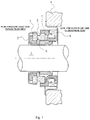
- Fig. 1 is a vertical cross-sectional view showing an example of the mechanical seal, which is an inside mechanical seal in a form of sealing sealed fluid on the high-pressure fluid side heading from the outer periphery of sliding surfaces toward the inner periphery to leak.
- the mechanical seal is provided, on the side of a rotating shaft 1 to drive a pump impeller (not shown) on the high-pressure fluid side, with an annular rotating-side seal ring 3, one sliding part, provided in a state of being integrally rotatable with the rotating shaft 1 via a sleeve 2, and at a pump housing 4, with an annular stationary-side seal ring 5, the other sliding part, provided in a state of being non-rotatable and axially movable.
- the rotating-side seal ring 3 and the stationary-side seal ring 5 slide in close contact with each other on sliding surfaces S mirror-finished by lapping or the like. That is, the mechanical seal prevents the sealed fluid from flowing out from the outer periphery of the rotating shaft 1 to the atmosphere side at the sliding surfaces S between the rotating-side seal ring 3 and the stationary-side seal ring 5.
- Fig. 1 shows a case where the width of the sliding surface of the rotating-side seal ring 3 is larger than the width of the sliding surface of the stationary-side seal ring 5, which is not limiting.
- the present invention can be applied to the opposite case as a matter of course.
- the material of the rotating-side seal ring 3 and the stationary-side seal ring 5 is selected from silicon carbide (SiC) excellent in wear resistance, carbon excellent in self-lubricity, and the like.
- SiC silicon carbide
- both of them may be SiC, or a combination in which the rotating-side seal ring 3 is SiC and the stationary-side seal ring 5 is carbon is possible.
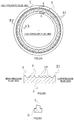
- dimples 10 are arranged on a sliding surface of at least one of the rotating-side seal ring 3 and the stationary-side seal ring 5 that slide relatively.
- a plurality of dimples 10 is arranged on a sliding surface S of the stationary-side seal ring 5.
- the rotating-side seal ring 3 need not be provided with dimples, or may be provided with dimples.
- the cross-sectional shape of the sliding part is a protruded shape as shown in Fig. 2C , and its top surface constitutes a flat sliding surface S.
- a large number of dimples 10 as shown in Fig. 2B are independently provided. These dimples 10 are provided not across the entire radial width of the sliding surface S but on a portion except a low-pressure fluid side sealing face IS formed such that a flat land portion R of a fixed width is left circumferentially on the low-pressure fluid side.
- the dimples 10 On the high-pressure fluid side of the sliding surface S, the dimples 10 may be provided to the rim.
- “dimples” are depressions formed on the flat sliding surface S, and are not limited to a particular shape.
- the planar shape of the depressions includes various shapes such as a circle, an ellipse, an oval, and a polygon
- the cross-sectional shape of the depressions includes various shapes such as a bowl shape and a square shape.
- the large number of dimples 10 formed on the sliding surface S have the function of holding part of liquid interposed as a hydrodynamic lubricating liquid film between the sliding surface S and an opposing sliding surface relatively sealing on the sliding surface S, to stabilize the lubricating liquid film.
- Each of the dimples 10 can be regarded as constituting a Rayleigh step as shown in Fig. 3 .
- a Rayleigh step 10a extending in a direction orthogonal to the cross section of the figure is formed on the sliding surface S(R) of the stationary-side seal ring 5.
- the sliding surface S of the rotating-side seal ring 3 is formed in a flat shape.
- dynamic pressure positive pressure
- the generation of the dynamic pressure increases the lubricating liquid film between the sliding surfaces, thus improving the lubrication performance.
- the lubrication performance is improved by dynamic pressure effect, there is a possibility that the amount of leakage increases.
- the amount of dimples is reduced to thin the lubricating liquid film to reduce the amount of leakage, the sliding surfaces S are more likely to contact to each other and generate friction.
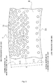
- Fig. 4 is a plan view of an enlarged portion of the sliding surface S, showing the state where the plurality of dimples 10 is disposed randomly on a part of the sliding surface except the low-pressure fluid side sealing face IS, and the area ratio of the plurality of dimples 10 is set lower on the low-pressure fluid side of the sliding surface S than on the high-pressure fluid side.
- the area ratio of the plurality of dimples is the sum of the opening areas of the dimples in the area of the part of the sliding surface S on which the dimples are provided.
- the area ratio is set lower on the low-pressure fluid side of the sliding surface S than on the high-pressure fluid side means that the area ratio in a unit circumferential length L is set lower on the low-pressure fluid side than on the high-pressure fluid side on all circumferential portions of the sliding surface S.
- the area ratio may be changed continuously, or may be changed discontinuously.
- the high-pressure fluid side and “the low-pressure fluid side” express radial sides of the sliding surface S.
- the division between a sliding surface on the high-pressure fluid side and a sliding surface on the low-pressure fluid side is made with a point of B/2, a midpoint of B, as a guide, where B is the width of a portion except the radial width of the low-pressure fluid side sealing face IS.
- the diameters of the individual dimples may be all different, or may be partly the same and partly different. It is essential only that the area ratio of the plurality of dimples 10 is set lower on the low-pressure fluid side of the sliding surface S than on the high-pressure fluid side.
- the low-pressure fluid side sealing face IS formed such that a flat land portion R of a fixed width is left circumferentially on the low-pressure fluid side is provided, the plurality of dimples 10 of different opening diameters is disposed mutually independently of the other dimples in a randomly distributed manner on a portion of the sliding surface except the low-pressure fluid side sealing face IS, and the area ratio of the plurality of dimples 10 is set lower on the low-pressure fluid side of the sliding surface S than on the high-pressure fluid side.
- the area ratio of the plurality of dimples 10 is preferably set at 30 to 50% to achieve both sealing and lubrication.
- the random distribution of the plurality of dimples 10 of different opening diameters is set according to a bearing characteristic number G (fluid viscosity ⁇ velocity / load) of the sliding surface or the like.
- the opening diameters are set to be distributed preferably in a range of 10 to 500 ⁇ m, and more preferably 30 to 100 ⁇ m.
- the depth of the plurality of dimples 10 is preferably set in a range of 50 to 10000 nm from the aspect of friction coefficient reduction, for example. When importance is attached to sliding characteristics at extremely low speed, the depth is preferably set in a range of 50 to 1000 nm, and more preferably 50 to 500 nm.
- the sliding component in the first embodiment achieves effects as below.
- the second embodiment is different from the first embodiment in that the opening diameter of a plurality of dimples is set approximately the same, but the other configuration is the same as that in the first embodiment. Redundant descriptions will be omitted.
- the opening diameter of a plurality of dimples 11 is set approximately the same, and its disposition density is set lower on the low-pressure fluid side of a sliding surface S than on the high-pressure fluid side.
- the disposition form of the plurality of dimples 11 may be a random distribution, or may be a regular distribution.
- dimples 11 provided in the vicinity of the outer peripheral side of a low-pressure fluid side sealing face IS formed such that a flat land portion R of a fixed width is left circumferentially on the low-pressure fluid side are disposed circumferentially at regular intervals.
- Dimples 11 on the other portion are distributed randomly. There is a portion on which dimples 11 are not provided in a radial middle portion on a sliding surface on the low-pressure fluid side.
- the sliding component according to the second embodiment achieves the same effects as the first embodiment, and additionally, is easy to produce since the opening diameter of the plurality of dimples 11 is set approximately the same.
- the sliding part is used as one of a pair of a rotating seal ring and a stationary seal ring in a mechanical seal device, it can also be used as a bearing sliding part that slides on a rotating shaft while sealing lubricating oil on axially one side of a cylindrical sliding surface.
- the sliding component can be used when high-pressure fluid is on the inner peripheral side.
- the first embodiment has been described on the case where a plurality of dimples of different opening diameters is distributed randomly.
- the second embodiment not covered by the present invention, is on the case where a plurality of dimples of approximately the same opening diameter is disposed randomly and regularly. Also not covered by the present invention is, for example, a plurality of dimples sequentially reduced in opening diameter from the high-pressure fluid side toward the low-pressure fluid side being regularly disposed.
Landscapes
- Engineering & Computer Science (AREA)
- General Engineering & Computer Science (AREA)
- Mechanical Engineering (AREA)
- Physics & Mathematics (AREA)
- Fluid Mechanics (AREA)
- Chemical & Material Sciences (AREA)
- Oil, Petroleum & Natural Gas (AREA)
- Sliding-Contact Bearings (AREA)
- Mechanical Sealing (AREA)
Claims (10)
- Gleitkomponente, die Folgendes aufweist:ein Paar von Gleitteilen (3, 5),eine Vielzahl von Vertiefungen (10; 11), die auf mindestens einer der Gleitflächen (S, IS) des Paars von Gleitteilen (3, 5) angeordnet sind, die so konfiguriert sind, dass sie relativ aufeinander gleiten, wobei die Vielzahl von Vertiefungen (10; 11) unabhängig von den anderen Vertiefungen (10; 11) vorgesehen sind, wobei eine Innenumfangsseite der Gleitfläche so konfiguriert ist, dass sie auf einer Niederdruckfluidseite angeordnet ist, eine Außenumfangsseite der Gleitfläche so konfiguriert ist, dass sie auf einer Hochdruckfluidseite angeordnet ist, wobei die Vielzahl von Vertiefungen (10; 11) ein Flächenverhältnis aufweist, das auf der Innenumfangsseite der Gleitfläche niedriger eingestellt ist als auf der Außenumfangsseite,dadurch gekennzeichnet, dassdie Vielzahl von Vertiefungen (10; 11) unterschiedliche Öffnungsdurchmesser hat, in einer zufällig verteilten Weise angeordnet ist und eine Anordnungsdichte hat, die auf der Innenumfangsseite der Gleitfläche niedriger eingestellt ist als auf der Außenumfangsseite.
- Gleitkomponente nach Anspruch 1, wobei die Öffnungsdurchmesser der Vielzahl von Vertiefungen (10; 11) in einem Bereich von 10 bis 500 µm eingestellt sind.
- Gleitkomponente nach Anspruch 1 oder 2, wobei das Flächenverhältnis der Vielzahl von Vertiefungen (10; 11) 30 bis 50% beträgt.
- Gleitkomponente nach einem der Ansprüche 1 bis 3, wobei die Vielzahl der Vertiefungen (10; 11) eine in einem Bereich von 50 bis 10.000 nm eingestellte Tiefe aufweist.
- Gleitkomponente nach einem der Ansprüche 1 bis 4, wobei die Vielzahl der Vertiefungen (10; 11) eine in einem Bereich von 50 bis 1000 nm eingestellte Tiefe aufweist.
- Gleitkomponente, die Folgendes aufweist:ein Paar von Gleitteilen (3, 5),eine Vielzahl von Vertiefungen (10; 11), die auf mindestens einer der Gleitflächen (S, IS) des Paars von Gleitteilen (3, 5) angeordnet sind, die so konfiguriert sind, dass sie relativ aufeinander gleiten, wobei die Vielzahl von Vertiefungen (10; 11) unabhängig von den anderen Vertiefungen (10; 11) vorgesehen sind, wobei eine Innenumfangsseite der Gleitfläche so konfiguriert ist, dass sie auf einer Hochdruckfluidseite angeordnet ist, eine Außenumfangsseite der Gleitfläche so konfiguriert ist, dass sie auf einer Niederdruckfluidseite angeordnet ist, wobei die mehreren Vertiefungen (10; 11) ein Flächenverhältnis aufweisen, das auf der Außenumfangsseite der Gleitfläche niedriger eingestellt ist als auf der Innenumfangsseite,dadurch gekennzeichnet, dassdie Vielzahl von Vertiefungen (10; 11) unterschiedliche Öffnungsdurchmesser hat, in einer zufällig verteilten Weise angeordnet ist und eine Anordnungsdichte hat, die auf der Außenumfangsseite der Gleitfläche niedriger eingestellt ist als auf der Innenumfangsseite.
- Gleitkomponente nach Anspruch 6, wobei die Öffnungsdurchmesser der Vielzahl von Vertiefungen (10; 11) in einem Bereich von 10 bis 500 µm eingestellt sind.
- Gleitkomponente nach Anspruch 6 oder 7, wobei das Flächenverhältnis der Vielzahl von Vertiefungen (10; 11) 30 bis 50% beträgt.
- Gleitkomponente nach einem der Ansprüche 6 bis 8, wobei die Vielzahl der Vertiefungen (10; 11) eine in einem Bereich von 50 bis 10.000 nm eingestellte Tiefe aufweist.
- Gleitkomponente nach einem der Ansprüche 6 bis 9, wobei die Vielzahl der Vertiefungen (10; 11) eine in einem Bereich von 50 bis 1000 nm eingestellte Tiefe aufweist.
Applications Claiming Priority (2)
| Application Number | Priority Date | Filing Date | Title |
|---|---|---|---|
| JP2015027032 | 2015-02-14 | ||
| PCT/JP2016/053657 WO2016129553A1 (ja) | 2015-02-14 | 2016-02-08 | しゅう動部品 |
Publications (3)
| Publication Number | Publication Date |
|---|---|
| EP3258145A1 EP3258145A1 (de) | 2017-12-20 |
| EP3258145A4 EP3258145A4 (de) | 2018-10-24 |
| EP3258145B1 true EP3258145B1 (de) | 2020-12-09 |
Family
ID=56615286
Family Applications (1)
| Application Number | Title | Priority Date | Filing Date |
|---|---|---|---|
| EP16749197.6A Active EP3258145B1 (de) | 2015-02-14 | 2016-02-08 | Gleitkomponente |
Country Status (6)
| Country | Link |
|---|---|
| US (1) | US10132411B2 (de) |
| EP (1) | EP3258145B1 (de) |
| JP (1) | JP6683630B2 (de) |
| KR (1) | KR101970231B1 (de) |
| CN (1) | CN107208805B (de) |
| WO (1) | WO2016129553A1 (de) |
Families Citing this family (19)
| Publication number | Priority date | Publication date | Assignee | Title |
|---|---|---|---|---|
| EP3499098B1 (de) | 2016-08-15 | 2024-04-24 | Eagle Industry Co., Ltd. | Gleitkomponente |
| AU2017318903A1 (en) * | 2016-09-01 | 2019-03-07 | Eagle Industry Co., Ltd. | Sliding component |
| US11739844B2 (en) | 2016-09-14 | 2023-08-29 | Eagle Industry Co., Ltd. | Mechanical seal |
| CN106286596A (zh) * | 2016-11-08 | 2017-01-04 | 湘潭大学 | 一种考虑热流固耦合含有渐变织构的液体静压推力轴承 |
| CN109964054B (zh) * | 2016-11-18 | 2021-09-17 | 伊格尔工业股份有限公司 | 滑动部件 |
| WO2018105505A1 (ja) * | 2016-12-07 | 2018-06-14 | イーグル工業株式会社 | しゅう動部品 |
| JP7102086B2 (ja) * | 2017-05-19 | 2022-07-19 | イーグル工業株式会社 | しゅう動部品 |
| KR102346413B1 (ko) * | 2017-05-19 | 2022-01-03 | 이구루코교 가부시기가이샤 | 슬라이딩 부품 |
| EP3653914B1 (de) | 2017-07-14 | 2024-09-18 | Eagle Industry Co., Ltd. | Gleitteile |
| KR102409059B1 (ko) * | 2017-10-03 | 2022-06-15 | 이구루코교 가부시기가이샤 | 슬라이딩 부품 |
| JP7179430B2 (ja) | 2018-01-12 | 2022-11-29 | イーグル工業株式会社 | 摺動部品 |
| EP3748205A4 (de) * | 2018-02-01 | 2021-11-10 | Eagle Industry Co., Ltd. | Gleitteile |
| EP3757432B1 (de) | 2018-02-21 | 2023-10-18 | Eagle Industry Co., Ltd. | Mechanische dichtung |
| US11852244B2 (en) | 2019-02-04 | 2023-12-26 | Eagle Industry Co., Ltd. | Sliding component and method of manufacturing sliding member |
| US11852241B2 (en) | 2019-02-04 | 2023-12-26 | Eagle Industry Co., Ltd. | Sliding component |
| JP7385006B2 (ja) * | 2020-04-07 | 2023-11-21 | イーグル工業株式会社 | 摺動部品 |
| EP4177488A4 (de) | 2020-07-06 | 2024-07-31 | Eagle Ind Co Ltd | Schiebekomponente |
| US11933303B2 (en) | 2020-07-06 | 2024-03-19 | Eagle Industry Co., Ltd. | Sliding component |
| CN114412741B (zh) * | 2021-12-23 | 2023-03-24 | 燕山大学 | 表面具有仿生疏水特性的海水轴向柱塞泵配流副 |
Family Cites Families (29)
| Publication number | Priority date | Publication date | Assignee | Title |
|---|---|---|---|---|
| US2577818A (en) * | 1947-08-18 | 1951-12-11 | Shaw Richard Woodside | Deep smooth surface finishing process |
| US4573690A (en) * | 1984-12-13 | 1986-03-04 | General Motors Corporation | Sealing surface and method |
| JPH01158853U (de) | 1988-03-18 | 1989-11-02 | ||
| DE3810741C1 (de) * | 1988-03-30 | 1989-11-09 | Fa. Carl Freudenberg, 6940 Weinheim, De | |
| DE4303237A1 (de) * | 1992-02-06 | 1993-10-21 | Eagle Ind Co Ltd | Gasdichtung |
| JPH11287329A (ja) | 1998-04-03 | 1999-10-19 | Eagle Ind Co Ltd | 摺動材 |
| JP2000169266A (ja) | 1998-12-04 | 2000-06-20 | Eagle Ind Co Ltd | 摺動材 |
| JP2000170768A (ja) * | 1998-12-04 | 2000-06-20 | Eagle Ind Co Ltd | 摺動材 |
| US6341782B1 (en) * | 2000-03-03 | 2002-01-29 | Surface Technologies Ltd | Lubricated seals having micropores |
| US6739238B2 (en) * | 2000-11-20 | 2004-05-25 | Nissan Motor Co., Ltd. | Sliding structure for a reciprocating internal combustion engine and a reciprocating internal combustion engine using the sliding structure |
| JP4205910B2 (ja) * | 2002-04-02 | 2009-01-07 | イーグル工業株式会社 | 摺動部品 |
| JP2004138128A (ja) * | 2002-10-16 | 2004-05-13 | Nissan Motor Co Ltd | 自動車エンジン用摺動部材 |
| US7771821B2 (en) * | 2003-08-21 | 2010-08-10 | Nissan Motor Co., Ltd. | Low-friction sliding member and low-friction sliding mechanism using same |
| US7270482B2 (en) * | 2004-02-05 | 2007-09-18 | Nissan Motor Co., Ltd. | Sliding device |
| JP2007092962A (ja) * | 2005-09-30 | 2007-04-12 | Ntn Corp | コネクティングロッド支持用軸受およびコネクティングロッド支持構造 |
| JP2007262977A (ja) * | 2006-03-28 | 2007-10-11 | Ntn Corp | 油圧ポンプ |
| WO2008013147A1 (fr) * | 2006-07-25 | 2008-01-31 | Eagle Industry Co., Ltd. | Dispositif d'etanchéité mécanique |
| CN200961698Y (zh) | 2006-10-12 | 2007-10-17 | 河北科技大学 | 一种动压型机械密封环 |
| CN100564962C (zh) * | 2007-02-15 | 2009-12-02 | 浙江工业大学 | 变分布多孔端面机械密封结构 |
| US8347683B2 (en) * | 2008-03-14 | 2013-01-08 | Varel International Ind., L.P. | Texturing of the seal surface for a roller cone rock bit |
| CN101672364B (zh) | 2009-10-15 | 2013-06-05 | 浙江工业大学 | 双列倾斜式方向性微孔端面无泄漏机械密封结构 |
| US8893538B2 (en) * | 2010-12-08 | 2014-11-25 | Fuji Kihan Co., Ltd. | Instantaneous heat treatment method for metal product |
| CN102022542B (zh) * | 2010-12-11 | 2013-04-03 | 浙江工业大学 | 一种负压型槽端面机械密封结构 |
| EP2752603B1 (de) * | 2011-09-03 | 2019-10-30 | Eagle Industry Co., Ltd. | Gleitkomponente |
| JP5968889B2 (ja) * | 2011-09-03 | 2016-08-10 | イーグル工業株式会社 | 摺動部品 |
| US9371912B2 (en) * | 2011-09-10 | 2016-06-21 | Eagle Industry Co., Ltd. | Sliding parts |
| JP6080845B2 (ja) * | 2012-05-21 | 2017-02-15 | イーグル工業株式会社 | 摺動部品 |
| WO2014124118A1 (en) * | 2013-02-06 | 2014-08-14 | Telleborg Sealing Solutions Us, Inc. | Friction-reducing geometric surface feature |
| CN103470762B (zh) | 2013-08-20 | 2016-05-18 | 浙江工业大学 | 倾斜渐变多孔端面非接触式机械密封结构 |
-
2016
- 2016-02-08 WO PCT/JP2016/053657 patent/WO2016129553A1/ja active Application Filing
- 2016-02-08 KR KR1020177021880A patent/KR101970231B1/ko active IP Right Grant
- 2016-02-08 US US15/547,422 patent/US10132411B2/en active Active
- 2016-02-08 JP JP2016574792A patent/JP6683630B2/ja active Active
- 2016-02-08 EP EP16749197.6A patent/EP3258145B1/de active Active
- 2016-02-08 CN CN201680007282.5A patent/CN107208805B/zh active Active
Non-Patent Citations (1)
| Title |
|---|
| None * |
Also Published As
| Publication number | Publication date |
|---|---|
| KR101970231B1 (ko) | 2019-04-18 |
| US10132411B2 (en) | 2018-11-20 |
| CN107208805B (zh) | 2019-03-19 |
| US20180017163A1 (en) | 2018-01-18 |
| EP3258145A1 (de) | 2017-12-20 |
| EP3258145A4 (de) | 2018-10-24 |
| WO2016129553A1 (ja) | 2016-08-18 |
| CN107208805A (zh) | 2017-09-26 |
| JP6683630B2 (ja) | 2020-04-22 |
| KR20170102531A (ko) | 2017-09-11 |
| JPWO2016129553A1 (ja) | 2017-11-24 |
Similar Documents
| Publication | Publication Date | Title |
|---|---|---|
| EP3258145B1 (de) | Gleitkomponente | |
| EP3508763A1 (de) | Gleitkomponente | |
| JP6076971B2 (ja) | 摺動部品 | |
| JP6080845B2 (ja) | 摺動部品 | |
| JP6800089B2 (ja) | しゅう動部品の製造方法 | |
| EP3650722B1 (de) | Gleitelement | |
| JP5995967B2 (ja) | 摺動部品 | |
| JP7143038B2 (ja) | 摺動部品 | |
| CN101696728B (zh) | 一种具有跨尺度表面织构特征的液体润滑端面密封结构 | |
| CN104214215B (zh) | 着陆轴承和磁轴承组件 | |
| JP7275028B2 (ja) | 摺動部品 |
Legal Events
| Date | Code | Title | Description |
|---|---|---|---|
| STAA | Information on the status of an ep patent application or granted ep patent |
Free format text: STATUS: THE INTERNATIONAL PUBLICATION HAS BEEN MADE |
|
| PUAI | Public reference made under article 153(3) epc to a published international application that has entered the european phase |
Free format text: ORIGINAL CODE: 0009012 |
|
| STAA | Information on the status of an ep patent application or granted ep patent |
Free format text: STATUS: REQUEST FOR EXAMINATION WAS MADE |
|
| 17P | Request for examination filed |
Effective date: 20170802 |
|
| AK | Designated contracting states |
Kind code of ref document: A1 Designated state(s): AL AT BE BG CH CY CZ DE DK EE ES FI FR GB GR HR HU IE IS IT LI LT LU LV MC MK MT NL NO PL PT RO RS SE SI SK SM TR |
|
| AX | Request for extension of the european patent |
Extension state: BA ME |
|
| DAV | Request for validation of the european patent (deleted) | ||
| DAX | Request for extension of the european patent (deleted) | ||
| A4 | Supplementary search report drawn up and despatched |
Effective date: 20180924 |
|
| RIC1 | Information provided on ipc code assigned before grant |
Ipc: F16C 17/04 20060101ALI20180918BHEP Ipc: F16J 15/34 20060101AFI20180918BHEP |
|
| GRAP | Despatch of communication of intention to grant a patent |
Free format text: ORIGINAL CODE: EPIDOSNIGR1 |
|
| STAA | Information on the status of an ep patent application or granted ep patent |
Free format text: STATUS: GRANT OF PATENT IS INTENDED |
|
| INTG | Intention to grant announced |
Effective date: 20200619 |
|
| GRAS | Grant fee paid |
Free format text: ORIGINAL CODE: EPIDOSNIGR3 |
|
| GRAA | (expected) grant |
Free format text: ORIGINAL CODE: 0009210 |
|
| STAA | Information on the status of an ep patent application or granted ep patent |
Free format text: STATUS: THE PATENT HAS BEEN GRANTED |
|
| AK | Designated contracting states |
Kind code of ref document: B1 Designated state(s): AL AT BE BG CH CY CZ DE DK EE ES FI FR GB GR HR HU IE IS IT LI LT LU LV MC MK MT NL NO PL PT RO RS SE SI SK SM TR |
|
| REG | Reference to a national code |
Ref country code: GB Ref legal event code: FG4D |
|
| REG | Reference to a national code |
Ref country code: AT Ref legal event code: REF Ref document number: 1343788 Country of ref document: AT Kind code of ref document: T Effective date: 20201215 Ref country code: CH Ref legal event code: EP |
|
| REG | Reference to a national code |
Ref country code: DE Ref legal event code: R096 Ref document number: 602016049432 Country of ref document: DE |
|
| REG | Reference to a national code |
Ref country code: IE Ref legal event code: FG4D |
|
| PG25 | Lapsed in a contracting state [announced via postgrant information from national office to epo] |
Ref country code: NO Free format text: LAPSE BECAUSE OF FAILURE TO SUBMIT A TRANSLATION OF THE DESCRIPTION OR TO PAY THE FEE WITHIN THE PRESCRIBED TIME-LIMIT Effective date: 20210309 Ref country code: RS Free format text: LAPSE BECAUSE OF FAILURE TO SUBMIT A TRANSLATION OF THE DESCRIPTION OR TO PAY THE FEE WITHIN THE PRESCRIBED TIME-LIMIT Effective date: 20201209 Ref country code: FI Free format text: LAPSE BECAUSE OF FAILURE TO SUBMIT A TRANSLATION OF THE DESCRIPTION OR TO PAY THE FEE WITHIN THE PRESCRIBED TIME-LIMIT Effective date: 20201209 Ref country code: GR Free format text: LAPSE BECAUSE OF FAILURE TO SUBMIT A TRANSLATION OF THE DESCRIPTION OR TO PAY THE FEE WITHIN THE PRESCRIBED TIME-LIMIT Effective date: 20210310 |
|
| REG | Reference to a national code |
Ref country code: AT Ref legal event code: MK05 Ref document number: 1343788 Country of ref document: AT Kind code of ref document: T Effective date: 20201209 |
|
| PG25 | Lapsed in a contracting state [announced via postgrant information from national office to epo] |
Ref country code: SE Free format text: LAPSE BECAUSE OF FAILURE TO SUBMIT A TRANSLATION OF THE DESCRIPTION OR TO PAY THE FEE WITHIN THE PRESCRIBED TIME-LIMIT Effective date: 20201209 Ref country code: BG Free format text: LAPSE BECAUSE OF FAILURE TO SUBMIT A TRANSLATION OF THE DESCRIPTION OR TO PAY THE FEE WITHIN THE PRESCRIBED TIME-LIMIT Effective date: 20210309 Ref country code: LV Free format text: LAPSE BECAUSE OF FAILURE TO SUBMIT A TRANSLATION OF THE DESCRIPTION OR TO PAY THE FEE WITHIN THE PRESCRIBED TIME-LIMIT Effective date: 20201209 |
|
| REG | Reference to a national code |
Ref country code: NL Ref legal event code: MP Effective date: 20201209 |
|
| PG25 | Lapsed in a contracting state [announced via postgrant information from national office to epo] |
Ref country code: NL Free format text: LAPSE BECAUSE OF FAILURE TO SUBMIT A TRANSLATION OF THE DESCRIPTION OR TO PAY THE FEE WITHIN THE PRESCRIBED TIME-LIMIT Effective date: 20201209 Ref country code: HR Free format text: LAPSE BECAUSE OF FAILURE TO SUBMIT A TRANSLATION OF THE DESCRIPTION OR TO PAY THE FEE WITHIN THE PRESCRIBED TIME-LIMIT Effective date: 20201209 |
|
| REG | Reference to a national code |
Ref country code: LT Ref legal event code: MG9D |
|
| PG25 | Lapsed in a contracting state [announced via postgrant information from national office to epo] |
Ref country code: RO Free format text: LAPSE BECAUSE OF FAILURE TO SUBMIT A TRANSLATION OF THE DESCRIPTION OR TO PAY THE FEE WITHIN THE PRESCRIBED TIME-LIMIT Effective date: 20201209 Ref country code: PT Free format text: LAPSE BECAUSE OF FAILURE TO SUBMIT A TRANSLATION OF THE DESCRIPTION OR TO PAY THE FEE WITHIN THE PRESCRIBED TIME-LIMIT Effective date: 20210409 Ref country code: SK Free format text: LAPSE BECAUSE OF FAILURE TO SUBMIT A TRANSLATION OF THE DESCRIPTION OR TO PAY THE FEE WITHIN THE PRESCRIBED TIME-LIMIT Effective date: 20201209 Ref country code: CZ Free format text: LAPSE BECAUSE OF FAILURE TO SUBMIT A TRANSLATION OF THE DESCRIPTION OR TO PAY THE FEE WITHIN THE PRESCRIBED TIME-LIMIT Effective date: 20201209 Ref country code: EE Free format text: LAPSE BECAUSE OF FAILURE TO SUBMIT A TRANSLATION OF THE DESCRIPTION OR TO PAY THE FEE WITHIN THE PRESCRIBED TIME-LIMIT Effective date: 20201209 Ref country code: SM Free format text: LAPSE BECAUSE OF FAILURE TO SUBMIT A TRANSLATION OF THE DESCRIPTION OR TO PAY THE FEE WITHIN THE PRESCRIBED TIME-LIMIT Effective date: 20201209 Ref country code: LT Free format text: LAPSE BECAUSE OF FAILURE TO SUBMIT A TRANSLATION OF THE DESCRIPTION OR TO PAY THE FEE WITHIN THE PRESCRIBED TIME-LIMIT Effective date: 20201209 |
|
| PG25 | Lapsed in a contracting state [announced via postgrant information from national office to epo] |
Ref country code: PL Free format text: LAPSE BECAUSE OF FAILURE TO SUBMIT A TRANSLATION OF THE DESCRIPTION OR TO PAY THE FEE WITHIN THE PRESCRIBED TIME-LIMIT Effective date: 20201209 Ref country code: AT Free format text: LAPSE BECAUSE OF FAILURE TO SUBMIT A TRANSLATION OF THE DESCRIPTION OR TO PAY THE FEE WITHIN THE PRESCRIBED TIME-LIMIT Effective date: 20201209 |
|
| REG | Reference to a national code |
Ref country code: DE Ref legal event code: R097 Ref document number: 602016049432 Country of ref document: DE |
|
| PG25 | Lapsed in a contracting state [announced via postgrant information from national office to epo] |
Ref country code: MC Free format text: LAPSE BECAUSE OF FAILURE TO SUBMIT A TRANSLATION OF THE DESCRIPTION OR TO PAY THE FEE WITHIN THE PRESCRIBED TIME-LIMIT Effective date: 20201209 Ref country code: IS Free format text: LAPSE BECAUSE OF FAILURE TO SUBMIT A TRANSLATION OF THE DESCRIPTION OR TO PAY THE FEE WITHIN THE PRESCRIBED TIME-LIMIT Effective date: 20210409 |
|
| PLBE | No opposition filed within time limit |
Free format text: ORIGINAL CODE: 0009261 |
|
| STAA | Information on the status of an ep patent application or granted ep patent |
Free format text: STATUS: NO OPPOSITION FILED WITHIN TIME LIMIT |
|
| REG | Reference to a national code |
Ref country code: BE Ref legal event code: MM Effective date: 20210228 |
|
| PG25 | Lapsed in a contracting state [announced via postgrant information from national office to epo] |
Ref country code: LI Free format text: LAPSE BECAUSE OF NON-PAYMENT OF DUE FEES Effective date: 20210228 Ref country code: LU Free format text: LAPSE BECAUSE OF NON-PAYMENT OF DUE FEES Effective date: 20210208 Ref country code: IT Free format text: LAPSE BECAUSE OF FAILURE TO SUBMIT A TRANSLATION OF THE DESCRIPTION OR TO PAY THE FEE WITHIN THE PRESCRIBED TIME-LIMIT Effective date: 20201209 Ref country code: AL Free format text: LAPSE BECAUSE OF FAILURE TO SUBMIT A TRANSLATION OF THE DESCRIPTION OR TO PAY THE FEE WITHIN THE PRESCRIBED TIME-LIMIT Effective date: 20201209 Ref country code: CH Free format text: LAPSE BECAUSE OF NON-PAYMENT OF DUE FEES Effective date: 20210228 |
|
| 26N | No opposition filed |
Effective date: 20210910 |
|
| GBPC | Gb: european patent ceased through non-payment of renewal fee |
Effective date: 20210309 |
|
| PG25 | Lapsed in a contracting state [announced via postgrant information from national office to epo] |
Ref country code: DK Free format text: LAPSE BECAUSE OF FAILURE TO SUBMIT A TRANSLATION OF THE DESCRIPTION OR TO PAY THE FEE WITHIN THE PRESCRIBED TIME-LIMIT Effective date: 20201209 Ref country code: SI Free format text: LAPSE BECAUSE OF FAILURE TO SUBMIT A TRANSLATION OF THE DESCRIPTION OR TO PAY THE FEE WITHIN THE PRESCRIBED TIME-LIMIT Effective date: 20201209 |
|
| PG25 | Lapsed in a contracting state [announced via postgrant information from national office to epo] |
Ref country code: ES Free format text: LAPSE BECAUSE OF FAILURE TO SUBMIT A TRANSLATION OF THE DESCRIPTION OR TO PAY THE FEE WITHIN THE PRESCRIBED TIME-LIMIT Effective date: 20201209 Ref country code: IE Free format text: LAPSE BECAUSE OF NON-PAYMENT OF DUE FEES Effective date: 20210208 Ref country code: GB Free format text: LAPSE BECAUSE OF NON-PAYMENT OF DUE FEES Effective date: 20210309 Ref country code: FR Free format text: LAPSE BECAUSE OF NON-PAYMENT OF DUE FEES Effective date: 20210209 |
|
| PG25 | Lapsed in a contracting state [announced via postgrant information from national office to epo] |
Ref country code: IS Free format text: LAPSE BECAUSE OF FAILURE TO SUBMIT A TRANSLATION OF THE DESCRIPTION OR TO PAY THE FEE WITHIN THE PRESCRIBED TIME-LIMIT Effective date: 20210409 |
|
| PG25 | Lapsed in a contracting state [announced via postgrant information from national office to epo] |
Ref country code: BE Free format text: LAPSE BECAUSE OF NON-PAYMENT OF DUE FEES Effective date: 20210228 |
|
| PG25 | Lapsed in a contracting state [announced via postgrant information from national office to epo] |
Ref country code: CY Free format text: LAPSE BECAUSE OF FAILURE TO SUBMIT A TRANSLATION OF THE DESCRIPTION OR TO PAY THE FEE WITHIN THE PRESCRIBED TIME-LIMIT Effective date: 20201209 |
|
| PG25 | Lapsed in a contracting state [announced via postgrant information from national office to epo] |
Ref country code: HU Free format text: LAPSE BECAUSE OF FAILURE TO SUBMIT A TRANSLATION OF THE DESCRIPTION OR TO PAY THE FEE WITHIN THE PRESCRIBED TIME-LIMIT; INVALID AB INITIO Effective date: 20160208 |
|
| PG25 | Lapsed in a contracting state [announced via postgrant information from national office to epo] |
Ref country code: MK Free format text: LAPSE BECAUSE OF FAILURE TO SUBMIT A TRANSLATION OF THE DESCRIPTION OR TO PAY THE FEE WITHIN THE PRESCRIBED TIME-LIMIT Effective date: 20201209 |
|
| PGFP | Annual fee paid to national office [announced via postgrant information from national office to epo] |
Ref country code: DE Payment date: 20231228 Year of fee payment: 9 |
|
| PG25 | Lapsed in a contracting state [announced via postgrant information from national office to epo] |
Ref country code: TR Free format text: LAPSE BECAUSE OF FAILURE TO SUBMIT A TRANSLATION OF THE DESCRIPTION OR TO PAY THE FEE WITHIN THE PRESCRIBED TIME-LIMIT Effective date: 20201209 |