WO2018043307A1 - しゅう動部品 - Google Patents
しゅう動部品 Download PDFInfo
- Publication number
- WO2018043307A1 WO2018043307A1 PCT/JP2017/030432 JP2017030432W WO2018043307A1 WO 2018043307 A1 WO2018043307 A1 WO 2018043307A1 JP 2017030432 W JP2017030432 W JP 2017030432W WO 2018043307 A1 WO2018043307 A1 WO 2018043307A1
- Authority
- WO
- WIPO (PCT)
- Prior art keywords
- sliding
- dimples
- dimple
- range
- sliding surface
- Prior art date
Links
Images


Classifications
-
- F—MECHANICAL ENGINEERING; LIGHTING; HEATING; WEAPONS; BLASTING
- F16—ENGINEERING ELEMENTS AND UNITS; GENERAL MEASURES FOR PRODUCING AND MAINTAINING EFFECTIVE FUNCTIONING OF MACHINES OR INSTALLATIONS; THERMAL INSULATION IN GENERAL
- F16C—SHAFTS; FLEXIBLE SHAFTS; ELEMENTS OR CRANKSHAFT MECHANISMS; ROTARY BODIES OTHER THAN GEARING ELEMENTS; BEARINGS
- F16C17/00—Sliding-contact bearings for exclusively rotary movement
- F16C17/04—Sliding-contact bearings for exclusively rotary movement for axial load only
-
- F—MECHANICAL ENGINEERING; LIGHTING; HEATING; WEAPONS; BLASTING
- F16—ENGINEERING ELEMENTS AND UNITS; GENERAL MEASURES FOR PRODUCING AND MAINTAINING EFFECTIVE FUNCTIONING OF MACHINES OR INSTALLATIONS; THERMAL INSULATION IN GENERAL
- F16C—SHAFTS; FLEXIBLE SHAFTS; ELEMENTS OR CRANKSHAFT MECHANISMS; ROTARY BODIES OTHER THAN GEARING ELEMENTS; BEARINGS
- F16C33/00—Parts of bearings; Special methods for making bearings or parts thereof
- F16C33/02—Parts of sliding-contact bearings
- F16C33/04—Brasses; Bushes; Linings
- F16C33/06—Sliding surface mainly made of metal
- F16C33/10—Construction relative to lubrication
- F16C33/1025—Construction relative to lubrication with liquid, e.g. oil, as lubricant
- F16C33/103—Construction relative to lubrication with liquid, e.g. oil, as lubricant retained in or near the bearing
-
- F—MECHANICAL ENGINEERING; LIGHTING; HEATING; WEAPONS; BLASTING
- F16—ENGINEERING ELEMENTS AND UNITS; GENERAL MEASURES FOR PRODUCING AND MAINTAINING EFFECTIVE FUNCTIONING OF MACHINES OR INSTALLATIONS; THERMAL INSULATION IN GENERAL
- F16C—SHAFTS; FLEXIBLE SHAFTS; ELEMENTS OR CRANKSHAFT MECHANISMS; ROTARY BODIES OTHER THAN GEARING ELEMENTS; BEARINGS
- F16C33/00—Parts of bearings; Special methods for making bearings or parts thereof
- F16C33/02—Parts of sliding-contact bearings
- F16C33/04—Brasses; Bushes; Linings
- F16C33/22—Sliding surface consisting mainly of rubber or synthetic rubber
-
- F—MECHANICAL ENGINEERING; LIGHTING; HEATING; WEAPONS; BLASTING
- F16—ENGINEERING ELEMENTS AND UNITS; GENERAL MEASURES FOR PRODUCING AND MAINTAINING EFFECTIVE FUNCTIONING OF MACHINES OR INSTALLATIONS; THERMAL INSULATION IN GENERAL
- F16C—SHAFTS; FLEXIBLE SHAFTS; ELEMENTS OR CRANKSHAFT MECHANISMS; ROTARY BODIES OTHER THAN GEARING ELEMENTS; BEARINGS
- F16C33/00—Parts of bearings; Special methods for making bearings or parts thereof
- F16C33/72—Sealings
- F16C33/74—Sealings of sliding-contact bearings
-
- F—MECHANICAL ENGINEERING; LIGHTING; HEATING; WEAPONS; BLASTING
- F16—ENGINEERING ELEMENTS AND UNITS; GENERAL MEASURES FOR PRODUCING AND MAINTAINING EFFECTIVE FUNCTIONING OF MACHINES OR INSTALLATIONS; THERMAL INSULATION IN GENERAL
- F16J—PISTONS; CYLINDERS; SEALINGS
- F16J15/00—Sealings
- F16J15/16—Sealings between relatively-moving surfaces
- F16J15/34—Sealings between relatively-moving surfaces with slip-ring pressed against a more or less radial face on one member
- F16J15/3404—Sealings between relatively-moving surfaces with slip-ring pressed against a more or less radial face on one member and characterised by parts or details relating to lubrication, cooling or venting of the seal
- F16J15/3408—Sealings between relatively-moving surfaces with slip-ring pressed against a more or less radial face on one member and characterised by parts or details relating to lubrication, cooling or venting of the seal at least one ring having an uneven slipping surface
- F16J15/3412—Sealings between relatively-moving surfaces with slip-ring pressed against a more or less radial face on one member and characterised by parts or details relating to lubrication, cooling or venting of the seal at least one ring having an uneven slipping surface with cavities
-
- F—MECHANICAL ENGINEERING; LIGHTING; HEATING; WEAPONS; BLASTING
- F16—ENGINEERING ELEMENTS AND UNITS; GENERAL MEASURES FOR PRODUCING AND MAINTAINING EFFECTIVE FUNCTIONING OF MACHINES OR INSTALLATIONS; THERMAL INSULATION IN GENERAL
- F16J—PISTONS; CYLINDERS; SEALINGS
- F16J15/00—Sealings
- F16J15/16—Sealings between relatively-moving surfaces
- F16J15/34—Sealings between relatively-moving surfaces with slip-ring pressed against a more or less radial face on one member
- F16J15/3404—Sealings between relatively-moving surfaces with slip-ring pressed against a more or less radial face on one member and characterised by parts or details relating to lubrication, cooling or venting of the seal
- F16J15/3408—Sealings between relatively-moving surfaces with slip-ring pressed against a more or less radial face on one member and characterised by parts or details relating to lubrication, cooling or venting of the seal at least one ring having an uneven slipping surface
- F16J15/3424—Sealings between relatively-moving surfaces with slip-ring pressed against a more or less radial face on one member and characterised by parts or details relating to lubrication, cooling or venting of the seal at least one ring having an uneven slipping surface with microcavities
-
- F—MECHANICAL ENGINEERING; LIGHTING; HEATING; WEAPONS; BLASTING
- F16—ENGINEERING ELEMENTS AND UNITS; GENERAL MEASURES FOR PRODUCING AND MAINTAINING EFFECTIVE FUNCTIONING OF MACHINES OR INSTALLATIONS; THERMAL INSULATION IN GENERAL
- F16C—SHAFTS; FLEXIBLE SHAFTS; ELEMENTS OR CRANKSHAFT MECHANISMS; ROTARY BODIES OTHER THAN GEARING ELEMENTS; BEARINGS
- F16C2240/00—Specified values or numerical ranges of parameters; Relations between them
- F16C2240/40—Linear dimensions, e.g. length, radius, thickness, gap
- F16C2240/44—Hole or pocket sizes
-
- F—MECHANICAL ENGINEERING; LIGHTING; HEATING; WEAPONS; BLASTING
- F16—ENGINEERING ELEMENTS AND UNITS; GENERAL MEASURES FOR PRODUCING AND MAINTAINING EFFECTIVE FUNCTIONING OF MACHINES OR INSTALLATIONS; THERMAL INSULATION IN GENERAL
- F16C—SHAFTS; FLEXIBLE SHAFTS; ELEMENTS OR CRANKSHAFT MECHANISMS; ROTARY BODIES OTHER THAN GEARING ELEMENTS; BEARINGS
- F16C2240/00—Specified values or numerical ranges of parameters; Relations between them
- F16C2240/40—Linear dimensions, e.g. length, radius, thickness, gap
- F16C2240/60—Thickness, e.g. thickness of coatings
-
- F—MECHANICAL ENGINEERING; LIGHTING; HEATING; WEAPONS; BLASTING
- F16—ENGINEERING ELEMENTS AND UNITS; GENERAL MEASURES FOR PRODUCING AND MAINTAINING EFFECTIVE FUNCTIONING OF MACHINES OR INSTALLATIONS; THERMAL INSULATION IN GENERAL
- F16C—SHAFTS; FLEXIBLE SHAFTS; ELEMENTS OR CRANKSHAFT MECHANISMS; ROTARY BODIES OTHER THAN GEARING ELEMENTS; BEARINGS
- F16C2240/00—Specified values or numerical ranges of parameters; Relations between them
- F16C2240/40—Linear dimensions, e.g. length, radius, thickness, gap
- F16C2240/70—Diameters; Radii
Definitions
- the present invention relates to a sliding part suitable for a sliding part, for example, a mechanical seal, a bearing, and the like.
- the present invention relates to a sliding component such as a seal ring or a bearing that requires a fluid to be interposed on a sliding surface to reduce friction and prevent fluid from leaking from the sliding surface.
- Patent Document 1 For example, in the invention described in Japanese Patent Application Laid-Open No. 11-287329 (hereinafter referred to as “Patent Document 1”), a large number of dimples having different depths are formed on the sliding surface, so that the other side slides during sliding. The load capacity due to the hydrodynamic bearing pressure generated in the fluid intervening with the surface is reduced in some dimples as the fluid temperature changes but increases in other dimples. In spite of this, the effect of always maintaining good sliding performance can be obtained. Further, the invention described in Japanese Patent Application Laid-Open No.
- Patent Document 2 forms a sliding surface by depositing a hard film on the surface of a base material made of a sintered ceramic material, By adopting a structure having a large number of dimples on the sliding surface, the wear resistance is improved and the liquid lubricity by dimples is improved.
- Patent Document 1 pays attention to the depth of the dimple provided on the sliding surface in order to always maintain good sliding performance regardless of the temperature change.
- the influence on the sliding characteristics (reduction of friction coefficient) by the ratio to the depth and the dimple area ratio is not considered.
- the invention described in Patent Document 2 is intended to improve liquid lubricity by providing dimples on the sliding surface.
- the influence of the dimple area ratio on the sliding characteristics is not considered.
- the present invention sets the ratio between the opening diameter and the depth of the dimple provided on the sliding surface within a predetermined range and randomly arranges the dimple area ratio within the predetermined range, thereby
- An object of the present invention is to provide a sliding component capable of improving the sliding characteristics in a wide range of the number of bearing characteristics.
- the sliding component of the present invention is firstly a sliding component in which a plurality of dimples are arranged on an annular sliding surface on at least one side of the pair of sliding components that slide relative to each other.
- the plurality of dimples have substantially the same opening diameter and are provided independently of each other dimples, and the ratio of the dimple depth h to the opening diameter D is in the range of 1/500 to 1/10.
- the dimple area ratio is set at random within a unit angle of 120 ° in the circumferential direction of the sliding surface so as to be in a range of 8% to 50%. According to this feature, the sliding characteristics can be improved in a wide range of the number of bearing characteristics on the sliding surface.
- the dimple processing becomes easy. Further, by setting the dimple area ratio within a unit angle of 120 ° in the circumferential direction of the sliding surface within a range of 8% to 50%, when SiC or carbon is used as the material of the sliding part, Even when the area ratio can be optimized and porous SiC is adopted as the material of the sliding part, continuous connection between the pores can be prevented.
- the sliding component of the present invention is secondly characterized in that, in the first feature, the ratio of the depth h to the diameter D of the dimple is set in a range of 1/400 to 1/20. Yes. According to this feature, the sliding characteristics can be further improved in a wide range of the number of bearing characteristics on the sliding surface.
- the area ratio of the dimples within a unit angle of 120 ° in the circumferential direction of the sliding surface is 35% to 45%. It is characterized by being randomly arranged to be in a range. According to this feature, it is possible to minimize leakage when the material of the sliding component is SiC or carbon.
- the sliding component of the present invention is fourthly characterized in that, in any one of the first to third features, the depth of the plurality of dimples is set to approximately 0.5 ⁇ m. According to this feature, the sliding characteristics at low speed can be improved.
- the sliding component of the present invention is fifthly characterized in that in any one of the first to fourth features, the opening diameter of the plurality of dimples is set to approximately 100 ⁇ m. According to this feature, the friction coefficient can be reduced in the range where the value of the bearing characteristic number G exceeds 7.6 ⁇ 10 ⁇ 8.
- the bearing constant G (viscosity ⁇ speed / load) is set to be in the range of 2 ⁇ 10 ⁇ 9 to 3 ⁇ 10 ⁇ 7 . According to this feature, the fluid lubrication transition point (Gc point) falls within this range, the friction coefficient is lowered, and boundary lubrication can be prevented.
- the present invention has the following excellent effects.
- the plurality of dimples have substantially the same opening diameter and are provided independently of each other dimples, and the ratio of the dimple depth h to the opening diameter D is 1/500 to 1/10.
- the dimple area ratio within a unit angle of 120 ° in the circumferential direction of the sliding surface is randomly arranged to be in the range of 8% to 50%. Sliding characteristics can be improved in a wide range of bearing characteristics. Further, since the plurality of dimples have substantially the same opening diameter, the dimple processing becomes easy.
- the dimple area ratio within a unit angle of 120 ° in the circumferential direction of the sliding surface within a range of 8% to 50%, when SiC or carbon is used as the material of the sliding part, Even when the area ratio can be optimized and porous SiC is adopted as the material of the sliding part, continuous connection between the pores can be prevented.
- the ratio of the dimple depth h to the diameter D is set in the range of 1/400 to 1/20, further improving the sliding characteristics over a wide range of bearing characteristics on the sliding surface. can do.
- the material of the sliding part is SiC or carbon. In this case, leakage can be minimized.
- the plurality of dimples can improve the sliding characteristics at a low speed by setting the depth to about 0.5 ⁇ m.
- the coefficient of friction can be reduced in the range where the value of the bearing characteristic number G exceeds 7.6 ⁇ 10 ⁇ 8.
- the bearing constant G (viscosity ⁇ speed / load) is 2 ⁇ 10 ⁇ 9 to 3 ⁇ 10.
- Example 1 of this invention With reference to FIG. 1 thru
- a mechanical seal which is an example of a sliding component, will be described as an example.
- the present invention is not limited to this, and for example, lubricating oil is applied to one axial side of a cylindrical sliding surface. It can also be used as a sliding part of a bearing that slides on a rotating shaft while being sealed.
- the outer peripheral side of the sliding part constituting the mechanical seal is described as the high pressure fluid side (sealed fluid side) and the inner peripheral side is described as the low pressure fluid side (atmosphere side)
- the present invention is not limited to this.
- the present invention can also be applied to the case where the high pressure fluid side and the low pressure fluid side are reversed.
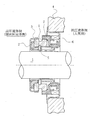
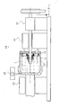
- FIG. 1 is a longitudinal sectional view showing an example of a mechanical seal, which is an inside type that seals a sealed fluid on the high-pressure fluid side that is about to leak from the outer periphery of the sliding surface toward the inner peripheral direction.
- a mechanical seal which is an inside type that seals a sealed fluid on the high-pressure fluid side that is about to leak from the outer periphery of the sliding surface toward the inner peripheral direction.
- annular ring which is one sliding component provided on the rotary shaft 1 side for driving a pump impeller (not shown) on the high pressure fluid side via a sleeve 2 so as to be rotatable integrally with the rotary shaft 1.
- the annular stationary side sealing ring 5 which is the other sliding part provided in the pump housing 4 in a non-rotating state and movable in the axial direction.
- FIG. 1 shows the case where the width of the sliding surface of the rotation-side sealing ring 3 is wider than the width of the sliding surface of the stationary-side sealing ring 5.
- the present invention can also be applied.
- the material of the rotating side sealing ring 3 and the stationary side sealing ring 5 is selected from silicon carbide (SiC) having excellent wear resistance and carbon having excellent self-lubricating properties.
- SiC silicon carbide
- the side seal ring 3 can be made of SiC and the fixed side seal ring 5 can be combined with carbon.
- dimples 10 are randomly arranged on at least one of the sliding surfaces of the rotating side sealing ring 3 and the stationary side sealing ring 5 that slide relative to each other.
- a plurality of dimples 10 are disposed on the sliding surface S of the stationary seal ring 5.
- the rotation-side sealing ring 3 may or may not be provided with dimples.
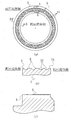
- the cross-sectional shape of the fixed-side sealing ring 5 is a convex shape as shown in FIG. 2C, and the top surface forms a flat sliding surface S.
- a large number of dimples 10 as shown in FIGS. 2A and 2B are provided independently of each other by being separated by a land portion R (flat portion).
- These dimples 10 are provided in the entire circumferential direction and radial direction of the sliding surface S.
- the dimple 10 may communicate with the high-pressure fluid side in the radial direction of the sliding surface S, but is isolated from the low-pressure fluid side by a flat sealing surface IS.
- the dimples 2 are provided continuously in the circumferential direction.
- the present invention is not limited thereto, and the dimples 2 may be provided intermittently in the circumferential direction.
- the “dimple” is a recess formed in the flat sliding surface S, and the shape thereof is not particularly limited.
- the planar shape of the recess includes a circle, an ellipse, an oval, or a rectangle
- the cross-sectional shape of the recess includes various shapes such as a bowl or a rectangle.
- a large number of dimples 10 formed on the sliding surface S allow a part of the liquid to intervene as a hydrodynamic lubricating liquid film between the sliding surface S and the opposing sliding surface that slides relative to the sliding surface S. Holding and stabilizing the lubricating liquid film.
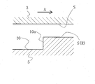
- Each dimple 10 can be regarded as constituting a Rayleigh step as shown in FIG.
- a Rayleigh step 10a extending in a direction orthogonal to the cross section of the drawing is formed on the sliding surface S (R) of the fixed side sealing ring 5, and the sliding surface S of the rotation side sealing ring 3 is flat. Is formed.
- the rotation-side sealing ring 3 moves relative to the direction indicated by the arrow, the fluid interposed between the sliding surfaces tends to follow in the direction of the arrow due to its viscosity.
- the presence of the Rayleigh step 10a causes the dynamic pressure (positive Pressure).
- the generation of dynamic pressure increases the lubricating liquid film between the sliding surfaces, thereby improving the lubricating performance. While the lubrication performance is improved by the dynamic pressure effect, the amount of leakage may increase, and if the amount of dimples is reduced to reduce the amount of leakage to reduce the amount of leakage, the sliding surface S contacts and causes wear. It becomes easy.
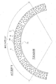
- FIG. 4 is an enlarged plan view of a part of the sliding surface S of the stationary seal ring 5 shown in FIG.
- a plurality of dimples 10 formed on the sliding surface are provided independently of each other dimples, and are arranged so that a plurality of circular dimples having substantially the same opening diameter are randomly distributed. Yes.
- the plurality of circular dimples 10 have substantially the same opening diameter and are provided independently of each other dimples, and the ratio of the dimple depth h to the diameter D ranges from 1/500 to 1/10. It is preferable to set to a value in the sense that the sliding characteristics are improved in a wide range of the number of bearing characteristics on the sliding surface.
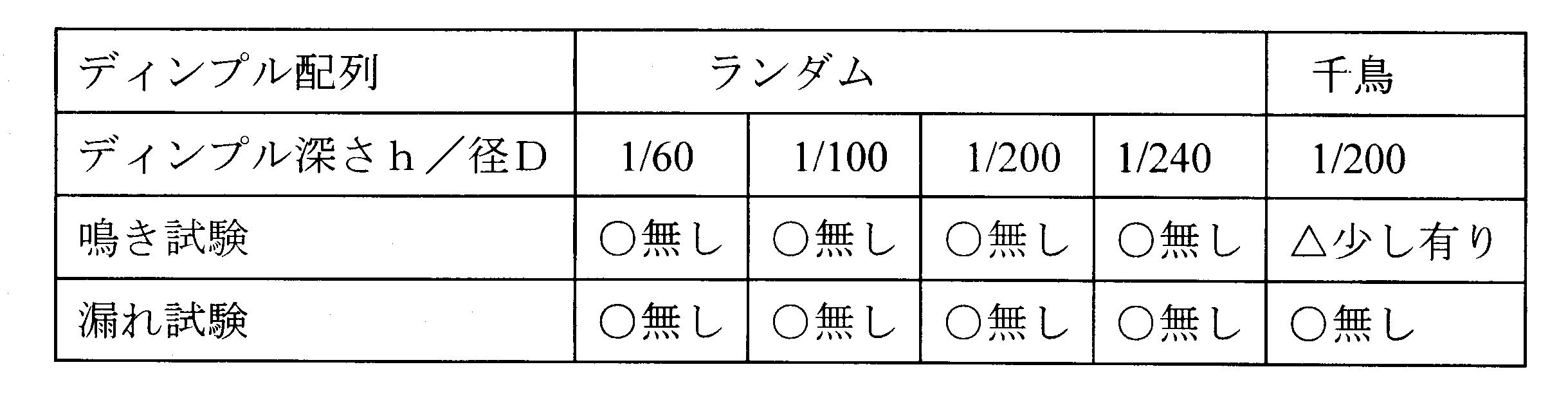
- the ratio of the dimple depth h to the diameter D is in the range of 1/400 to 1/20, more preferably the ratio of the dimple depth h to the diameter D is 1/240 to 1/60. Range.
- the depth h is about 0.5 ⁇ m
- the opening diameter D is set to about 100 ⁇ m.
- the ratio of the dimple depth h to the opening diameter D is 1/200.
- the depth h of the dimple is 0.5 ⁇ m
- h / D 1/500
- D 250 ⁇ m
- h / D 1/10
- D 5 ⁇ m.
- approximately 0.5 ⁇ m means a material within the range of 0.5 ⁇ 10% ⁇ m
- approximately 100 ⁇ m means a material within the range of 100 ⁇ 10% ⁇ m.
- Table 1 shows the evaluation results of the sliding surface squeal test and the leak test when the ratio of the dimple depth h to the diameter D is changed.
- One of the sliding parts was silicon carbide (SiC) and the other was carbon. According to the results in Table 1, it can be seen that both the squealing and leakage are good when the ratio of the dimple depth h to the diameter D is at least in the range of 1/60 to 1/240.
- the fluid lubrication transition point shifts to the low G side as the dimple depth h decreases, and the fluid lubrication transition point shifts to the high rotation side as the depth h increases. It has been determined that higher rotational speeds are required to maintain lubrication.
- the dimple opening diameter D is the average value of the “maximum diameter portion” and the “minimum diameter portion” that follow the boundary line between the unprocessed surface and the processed surface.
- the surface where the shape has changed in the depth direction by 0.05 ⁇ m or more excluding the surface roughness of the sliding surface S, or the surface roughness of the sliding surface S The position at which the shape of 1/10 or more of the deepest part of the dimple depth excluding is changed in the depth direction is defined as the boundary between the unprocessed surface and the processed surface.
- the opening diameter D is substantially the same means that within the range of ⁇ 10% of the design value of the opening diameter.
- the dimple shape is other than a circle, for example, the following equivalent diameter is adopted as the opening diameter in the case of an ellipse, an ellipse, or a rectangle.
- Equivalent diameter 4 ⁇ (Dimple cross-sectional area / Dimple circumference)
- the depth h of the dimple 10 will be described with reference to FIG.
- the cross-sectional shape of the dimple 10 is a shape as shown in FIG. 5
- an average position within the range of D / 4 from the center of the processed surface is calculated, and the calculated height and the height dimension to the unprocessed surface are calculated. Depth h.
- the plurality of circular dimples 10 having substantially the same opening diameter are arranged so as to be randomly distributed in the circumferential direction and the radial direction of the sliding surface S.
- the area ratio of the dimple 10 within the unit angle of 120 ° in the circumferential direction (the total area of all the dimples / the area of the sliding surface) is set in a range of 8% to 50%.
- the area ratio of the dimple 10 is determined to an appropriate value depending on the sealing pressure of the sliding surface S. For example, a rotational test of the sliding component is performed based on the sealing pressure, and the amount of leakage at the sealing pressure is determined. It is desirable to check and set.
- the area ratio of the dimple 10 needs to be set according to the material of the sliding part. For example, in the case of porous SiC, if the area ratio of the dimple 10 is 10% or more, the pores may be continuously connected to each other, so about 8% is appropriate.
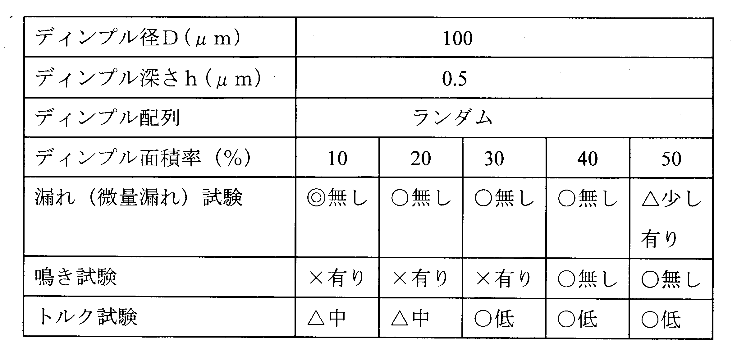
- Table 2 shows the evaluation results of the sliding surface leakage (trace leakage) test, squeal test, and torque test when the area ratio of the dimple 10 is changed.
- One of the sliding parts was silicon carbide (SiC) and the other was carbon. From the results of Table 2, it can be seen from the aspects of leakage, squealing, and torque that the area ratio of the dimple 10 within a unit angle of 120 ° in the circumferential direction of the sliding surface S is good in the range of 35 to 45%.
- FIG. 6 is a reference diagram showing the relationship between the coefficient of friction obtained by the rotational sliding test and the bearing characteristic number G.
- the inner diameter of the sliding surface of the sliding part used in the rotational sliding test is ⁇ 18 mm
- the width of the sliding surface is 1.8 mm
- the dimple area ratio is 40%
- the dimple depth h is all 0.1 ⁇ m.
- the dimple opening diameter is within the range where the value of the bearing characteristic number G exceeds 7.6 ⁇ 10 ⁇ 8. It can be seen that the larger the coefficient, the lower the friction coefficient.
- Gc point there is a fluid lubrication transition point (hereinafter referred to as “Gc point”) in the opening diameter of each dimple. In the examples of ⁇ 50 ⁇ m, ⁇ 75 ⁇ m, and ⁇ 100 ⁇ m, the smaller the dimple opening diameter, the lower the Gc point. It can be seen that the friction coefficient at the point Gc is lower. According to the test results of FIG.
- the bearing constant G (viscosity ⁇ speed / load) is 2 ⁇ 10 ⁇ 9 to 3 ⁇ 10.
- the friction coefficient is as low as 0.1 or less, the fluid lubrication transition point (Gc point) falls within this range, and boundary lubrication does not occur.
- the main body of the testing machine 19 includes a casing 13 that supports the stationary ring 11 in a non-rotating state via a spring 12, a rotating shaft 14 that is rotatably inserted into the inner periphery of the casing 13, and the rotating shaft 14.
- the stationary ring 11 and the rotating ring 15 that are axially opposed to each other are supported on the outer periphery, and the sealing target liquid L is sealed in a sealed space surrounded by the rotating ring 15, the casing 13, and the rotating shaft 14. .
- static pressure gas bearings are adopted for the bearing portions 16 on both sides so that the sliding torque of the mechanical seal can be accurately measured. Further, the torque is measured by two kinds of methods, that is, a torque meter 17 and a load cell 18 by a cantilever method, and a measurement error is eliminated by double check.
- the sliding component according to the embodiment of the present invention has the following remarkable effects.
- the plurality of dimples 10 are provided independently of each other dimples, the ratio of the dimple depth h to the diameter D is set in the range of 1/500 to 1/10, and the sliding
- the surface area of the dimple 10 within the unit angle 120 ° in the circumferential direction of the surface S is randomly arranged so as to be in the range of 8% to 50%, so that the bearing characteristic number on the sliding surface is wide.
- the sliding characteristics can be improved.
- the plurality of dimples 10 have substantially the same opening diameter, the dimple 10 can be easily processed.
- the area ratio of the dimple 10 within a unit angle of 120 ° in the circumferential direction of the sliding surface S should be in the range of 8% to 50%, so that when dipping the SiC or carbon as the material of the sliding part, Even when the area ratio of 10 can be optimized and porous SiC is adopted as the material of the sliding component, continuous connection between the pores can be prevented.
- the ratio of the dimple depth h to the diameter D in the range of 1/400 to 1/20, the sliding characteristics are further improved over a wide range of bearing characteristics on the sliding surface. can do.
- the ratio of the dimple depth h to the diameter D becomes 1/200, and the number of bearing characteristics on the sliding surface is further increased.
- the sliding characteristics can be improved in a wide range.
- the material of the sliding part is SiC or carbon, there is no leakage when the area ratio of the dimple within a unit angle of 120 ° in the circumferential direction of the sliding surface is 10% to 45%.
- the area ratio is 35% to 50% and there is no noise.
- the dimple area ratio is 25% to 50% and the torque is low. Therefore, the dimple area ratio is 35 to 45%. preferable.
- the sliding characteristics at low speed can be improved.
- the opening diameters of the plurality of dimples are set to about 100 ⁇ m, the friction coefficient can be reduced in the range where the value of the bearing characteristic number G exceeds 7.6 ⁇ 10 ⁇ 8.
- the ratio of the dimple depth h to the diameter D is 1/200, and the sliding surface is further increased. The sliding characteristics can be improved in a wide range of bearing characteristics.
- the sliding component is used for at least one of the pair of rotation sealing rings and the fixing sealing ring in the mechanical seal device. It can also be used as a sliding part of a bearing that slides on a rotating shaft while sealing lubricating oil.
- the plurality of dimples has a depth h of about 0.5 ⁇ m and an opening diameter D of about 100 ⁇ m has been described.
- the ratio between the dimple depth h and the diameter D is not limited to these, and may be set in a range of 1/500 to 1/10.
- the present invention is not limited to this, and the area ratio of the dimples within a unit angle of 120 ° in the circumferential direction of the sliding surface may be in the range of 30% to 50%.
Landscapes
- Engineering & Computer Science (AREA)
- General Engineering & Computer Science (AREA)
- Mechanical Engineering (AREA)
- Chemical & Material Sciences (AREA)
- Oil, Petroleum & Natural Gas (AREA)
- Mechanical Sealing (AREA)
- Sliding-Contact Bearings (AREA)
Abstract
Description
また、特開2000-169266号公報(以下、「特許文献2」という。)に記載の発明は、焼結したセラミックス材料からなる下地材の表面に硬質皮膜を蒸着したしゅう動面を形成し、このしゅう動面に、多数のディンプルを有する構成とすることにより、耐摩耗性の向上を図ると共に、ディンプルによる液体潤滑性の向上を図るようにしたものである。
また、特許文献2に記載の発明は、しゅう動面にディンプルを設けることで液体潤滑性の向上を図るようにしたものであるが、特許文献1と同様、ディンプルの開口径と深さとの比、及び、ディンプルの面積率によるしゅう動特性(摩擦係数低減)への影響については考察されていない。
この特徴によれば、しゅう動面における軸受特性数の広い範囲においてしゅう動特性を向上することができる。
また、複数のディンプルは、開口径が略同一であるため、ディンプルの加工が容易となる。
さらに、しゅう動面の円周方向の単位角度120°内におけるディンプルの面積率は8%~50%の範囲とすることにより、しゅう動部品の材質としてSiCあるいはカーボンを採用した場合、ディンプル10の面積率を最適にできると共にしゅう動部品の材質としてポーラスSiCを採用した場合でも、気孔同士の連続的なつながりを防止することができる。
この特徴によれば、より一層、しゅう動面における軸受特性数の広い範囲においてしゅう動特性を向上することができる。
この特徴によれば、しゅう動部品の材質がSiCあるいはカーボンである場合の漏れを最小限に抑制することができる。
この特徴によれば、低速でのしゅう動特性を向上することができる。
この特徴によれば、軸受特性数Gの値が7.6×10⁻⁸を超える範囲で摩擦係数を小さくすることができる。
この特徴によれば、流体潤滑遷移点(Gc点)がこの範囲に入り、摩擦係数を低く、境界潤滑になることを防止できる。
(1)複数のディンプルは、開口径が略同一であって、相互に他のディンプルと独立して設けられ、ディンプルの深さhと開口径Dとの比は1/500~1/10の範囲に設定され、かつ、しゅう動面の円周方向の単位角度120°内におけるディンプルの面積率は8%~50%の範囲になるようにランダムに配設されることにより、しゅう動面における軸受特性数の広い範囲においてしゅう動特性を向上することができる。
また、複数のディンプルは、開口径が略同一であるため、ディンプルの加工が容易となる。
さらに、しゅう動面の円周方向の単位角度120°内におけるディンプルの面積率は8%~50%の範囲とすることにより、しゅう動部品の材質としてSiCあるいはカーボンを採用した場合、ディンプル10の面積率を最適にできると共にしゅう動部品の材質としてポーラスSiCを採用した場合でも、気孔同士の連続的なつながりを防止することができる。
なお、以下の実施例においては、しゅう動部品の一例であるメカニカルシールを例にして説明するが、これに限定されることなく、例えば、円筒状しゅう動面の軸方向一方側に潤滑油を密封しながら回転軸としゅう動する軸受のしゅう動部品として利用することも可能である。
なお、メカニカルシールを構成するしゅう動部品の外周側を高圧流体側(被密封流体側)、内周側を低圧流体側(大気側)として説明するが、本発明はこれに限定されることなく、高圧流体側と低圧流体側とが逆の場合も適用可能である。
なお、図1では、回転側密封環3のしゅう動面の幅が固定側密封環5のしゅう動面の幅より広い場合を示しているが、これに限定されることなく、逆の場合においても本発明を適用出来ることはもちろんである。
相対しゅう動する回転側密封環3あるいは固定側密封環5の少なくともいずれか一方のしゅう動面には、図2に示すように、ディンプル10がランダムに配設されている。
本例では、固定側密封環5のしゅう動面Sに複数のディンプル10が配設されている。この場合、回転側密封環3にはディンプルは設けられなくても、設けられてもよい。回転側密封環3にディンプルを設ける場合には、固定側密封環5のしゅう動面Sに設けられるディンプル10と同じ(サイズ、比率)になるように設けるのが望ましい。
ディンプル10は、しゅう動面Sの径方向において、高圧流体側と連通してもよいが、低圧流体側とは平坦なシール面ISにより隔離される。
また、本例では、ディンプル2は、周方向に連続して設けられる場合を示しているが、これに限らず、周方向に断続的に設けられてもよい。
そして、しゅう動面Sに形成された多数のディンプル10は、このしゅう動面Sと相対しゅう動する相手側しゅう動面との間に流体力学的な潤滑液膜として介入する液体の一部を保持して、潤滑液膜を安定化させる機能を有するものである。
図3において、固定側密封環5のしゅう動面S(R)には図の断面と直交する方向に延びるレイリーステップ10aが形成されており、回転側密封環3のしゅう動面Sは平坦に形成されている。回転側密封環3が矢印で示す方向に相対移動すると、両しゅう動面間に介在する流体が、その粘性によって矢印方向に追随移動しようとし、その際、レイリーステップ10aの存在によって動圧(正圧)を発生する。動圧の発生によりしゅう動面間の潤滑液膜が増大され、潤滑性能が向上されるものである。動圧効果により潤滑性能が向上させられる一方、漏れ量が増える恐れがあり、漏れ量を減らすため潤滑液膜を薄くするようにディンプルの量を少なくすると、しゅう動面Sが接触し摩耗を起こしやすくなる。
図4において、しゅう動面に形成された複数のディンプル10は、相互に他のディンプルと独立して設けられ、開口径が略同一の複数の円形のディンプルがランダムに分布するように配置されている。
図4に示すディンプルの場合、深さhは略0.5μmであり、開口径Dは略100μmに設定されている。この場合、ディンプルの深さhと開口径Dとの比は1/200となる。
また、たとえば、ディンプルの深さhを0.5μmとした場合にh/D=1/500とすると、D=250μmとなり、さらに、h/D=1/10とすると、D=5μmとなる。
なお、しゅう動部品の一方は炭化ケイ素(SiC)、他方はカーボンとした。
また、開口径Dが略同一とは、開口径の設計値の±10%の範囲内のものを意味する。 ディンプルの形状が円以外の場合、たとえば、楕円、長円あるいは矩形の場合における開口径については、便宜的に以下の等価直径を採用する。
等価直径=4×(ディンプルの断面積/ディンプルの周の長さ)
たとえば、1辺の長さがaの正方形の場合、等価直径=4a2/4a=aとなる。
ディンプル10の断面形状が図5に示すような形状である場合、加工面の中心からD/4の範囲内の平均位置を算出し、当該算出位置と未加工面までの高さ寸法をディンプル10の深さhとする。
図4に示すように、開口径が略同一の複数の円形のディンプル10は、しゅう動面Sの周方向及び径方向にランダムに分布するように配設されるものであり、しゅう動面Sの円周方向の単位角度120°内におけるディンプル10の面積率(全てのディンプルの面積の合計/しゅう動面の面積)が8%~50%の範囲になるように設定される。
ディンプル10の面積率は、しゅう動面Sの密封圧に依存して適切な値に定められるものであり、たとえば、密封圧に基づきしゅう動部品の回転試験を行い、当該密封圧における漏れ量を確認して設定することが望ましい。
また、ディンプル10の面積率は、しゅう動部品の材質により設定する必要がある。たとえば、ポーラスSiCの場合、ディンプル10の面積率を10%以上にすると気孔同士が連続的につながる恐れがあるため、8%程度が適当である。
なお、しゅう動部品の一方は炭化ケイ素(SiC)、他方はカーボンとした。
(1)乱数を用いて金属マスクにあける孔の位置を決定する。
(2)決定された位置に金属マスクにレーザ加工などで孔をあける。
(3)ランダムに孔のあけられた金属マスクを対象となるしゅう動部品のしゅう動面上に設置する。
(4)金属マスクの上からフェムト秒レーザを照射したり、イオンエッチングなどで金属マスクの孔を利用してしゅう動面にディンプルを形成する。しゅう動面には、開口径の同一のディンプルが所定の分布でもって一様に配置される。
回転しゅう動試験に用いられた摺動部品のしゅう動面の内径はφ18mm、しゅう動面の幅は1.8mmであり、ディンプル面積率は40%、ディンプルの深さhはすべて0.1μm、ディンプルの開口径Dは、それぞれ、φ50μm(h/D=1/500)、φ75μm(h/D=1/750)、φ100μ(h/D=1/1000)、の3種類であった。

図6の試験結果によれば、次のことがいえる。
(1)G値が7.6×10⁻⁸を超える範囲でディンプル開口径が大きいほど(h/Dの比が小さいほど)、摩擦係数は下がる。
(2)ディンプル開口径が小さくなるほど(h/Dの比が大きくなるほど)Gc点が低G側にシフトし、さらに、Gc点における摩擦係数が低くなる。
試験機19の本体部分には、固定環11をバネ12を介して非回転状態に支持するケーシング13と、このケーシング13の内周に回転自在に挿通された回転軸14と、この回転軸14の外周に支持された、固定環11と軸方向に対向される回転環15とを備え、回転環15、ケーシング13、回転軸14で囲まれた密封空間には密封対象液Lが封入される。
(1)複数のディンプル10は、相互に他のディンプルと独立して設けられ、ディンプルの深さhと径Dとの比は1/500~1/10の範囲に設定され、かつ、しゅう動面Sの円周方向の単位角度120°内におけるディンプル10の面積率は8%~50%の範囲になるようにランダムに配設されることにより、しゅう動面における軸受特性数の広い範囲においてしゅう動特性を向上することができる。
また、複数のディンプル10は、開口径が略同一であるため、ディンプル10の加工が容易となる。
さらに、しゅう動面Sの円周方向の単位角度120°内におけるディンプル10の面積率は8%~50%の範囲とすることにより、しゅう動部品の材質としてSiCあるいはカーボンを採用した場合、ディンプル10の面積率を最適にできると共にしゅう動部品の材質としてポーラスSiCを採用した場合でも、気孔同士の連続的なつながりを防止することができる。
(2)ディンプルの深さhと径Dとの比が1/400~1/20の範囲に設定されることにより、より一層、しゅう動面における軸受特性数の広い範囲においてしゅう動特性を向上することができる。
複数のディンプルの深さが略0.5μm、開口径が略100μmに設定されると、ディンプルの深さhと径Dとの比は1/200となり、より一層、しゅう動面における軸受特性数の広い範囲においてしゅう動特性を向上することができる。
(3)しゅう動部品の材質がSiCあるいはカーボンである場合、しゅう動面の円周方向の単位角度120°内におけるディンプルの面積率が10%~45%の範囲で漏れがなく、また、ディンプルの面積率が35%~50%の範囲で鳴きがなく、更に、ディンプルの面積率が25%~50%の範囲で低トルクであることから、ディンプルの面積率は35~45%の範囲が好ましい。
(4)複数のディンプルの深さが略0.5μmに設定されると、低速でのしゅう動特性を向上することができる。また、複数のディンプルの開口径が略100μmに設定されると、軸受特性数Gの値が7.6×10⁻⁸を超える範囲で摩擦係数を小さくすることができる。また、複数のディンプルの深さが略0.5μmであって開口径が略100μmに設定されると、ディンプルの深さhと径Dとの比は1/200となり、より一層、しゅう動面における軸受特性数の広い範囲においてしゅう動特性を向上することができる。
(5)回転しゅう動試験によって得られた摩擦係数と軸受定数G(粘度×速度/荷重)との関係において、軸受定数G(粘度×速度/荷重)の範囲を2×10-9~3×10-7 と設定することにより、流体潤滑遷移点(Gc点)がこの範囲に入り、摩擦係数を低く、境界潤滑になることを防止できる。
2 スリーブ
3 回転側密封環
4 ハウジング
5 固定側密封環
6 コイルドウェーブスプリング
7 ベローズ
10 ディンプル
19 試験機
11 固定環
12 バネ
13 ケーシング
14 回転軸
15 回転環
16 軸受部分
17 トルクメータ
18 ロードセル
S しゅう動面
R ランド部
Claims (6)
- 一対のしゅう動部品の互いに相対しゅう動する少なくとも一方側の環状のしゅう動面にディンプルが複数配置されたしゅう動部品において、
前記複数のディンプルは、開口径が略同一であって、相互に他のディンプルと独立して設けられ、ディンプルの深さhと開口径Dとの比は1/500~1/10の範囲に設定され、かつ、前記しゅう動面の円周方向の単位角度120°内における前記ディンプルの面積率は8%~50%の範囲になるようにランダムに配設されることを特徴とするしゅう動部品。 - 前記ディンプルの深さhと径Dとの比は1/400~1/20の範囲に設定されることを特徴とする請求項1記載のしゅう動部品。
- 前記しゅう動面の円周方向の単位角度120°内における前記ディンプルの面積率は35%~45%の範囲になるようにランダムに配設されることを特徴とする請求項1又は2に記載のしゅう動部品。
- 前記複数のディンプルは、深さが略0.5μmに設定されることを特徴とする請求項1ないし3のいずれか1項に記載のしゅう動部品。
- 前記複数のディンプルは、開口径が略100μmに設定されることを特徴とする請求項1ないし4のいずれか1項に記載のしゅう動部品。
- 回転しゅう動試験によって得られた摩擦係数と軸受定数G(粘度×速度/荷重)との関係において、前記軸受定数G(粘度×速度/荷重)が2×10-9~3×10-7の範囲にあるように設定されることを特徴とする請求項1ないし5のいずれか1項に記載のしゅう動部品。
Priority Applications (5)
| Application Number | Priority Date | Filing Date | Title |
|---|---|---|---|
| JP2018537213A JPWO2018043307A1 (ja) | 2016-09-01 | 2017-08-25 | しゅう動部品 |
| US16/322,302 US20190170257A1 (en) | 2016-09-01 | 2017-08-25 | Sliding component |
| EP17846312.1A EP3508763A4 (en) | 2016-09-01 | 2017-08-25 | SLIDING COMPONENT |
| CN201780050014.6A CN109563935A (zh) | 2016-09-01 | 2017-08-25 | 滑动部件 |
| AU2017318903A AU2017318903A1 (en) | 2016-09-01 | 2017-08-25 | Sliding component |
Applications Claiming Priority (2)
| Application Number | Priority Date | Filing Date | Title |
|---|---|---|---|
| JP2016171322 | 2016-09-01 | ||
| JP2016-171322 | 2016-09-01 |
Publications (1)
| Publication Number | Publication Date |
|---|---|
| WO2018043307A1 true WO2018043307A1 (ja) | 2018-03-08 |
Family
ID=61300948
Family Applications (1)
| Application Number | Title | Priority Date | Filing Date |
|---|---|---|---|
| PCT/JP2017/030432 WO2018043307A1 (ja) | 2016-09-01 | 2017-08-25 | しゅう動部品 |
Country Status (6)
| Country | Link |
|---|---|
| US (1) | US20190170257A1 (ja) |
| EP (1) | EP3508763A4 (ja) |
| JP (1) | JPWO2018043307A1 (ja) |
| CN (1) | CN109563935A (ja) |
| AU (1) | AU2017318903A1 (ja) |
| WO (1) | WO2018043307A1 (ja) |
Cited By (5)
| Publication number | Priority date | Publication date | Assignee | Title |
|---|---|---|---|---|
| CN111989501A (zh) * | 2018-04-18 | 2020-11-24 | 兼房株式会社 | 带凹部的工件及凹部的加工方法 |
| US11035411B2 (en) * | 2017-07-14 | 2021-06-15 | Eagle Industry Co., Ltd. | Sliding parts |
| US11053975B2 (en) | 2017-05-19 | 2021-07-06 | Eagle Industry Co., Ltd | Sliding component |
| US11248707B2 (en) | 2017-05-19 | 2022-02-15 | Eagle Industry Co., Ltd | Sliding component |
| US11708911B2 (en) | 2017-10-03 | 2023-07-25 | Eagle Industry Co., Ltd. | Sliding component |
Families Citing this family (9)
| Publication number | Priority date | Publication date | Assignee | Title |
|---|---|---|---|---|
| CN109563934A (zh) | 2016-08-15 | 2019-04-02 | 伊格尔工业股份有限公司 | 滑动部件 |
| CN111542713A (zh) | 2018-01-12 | 2020-08-14 | 伊格尔工业股份有限公司 | 滑动部件 |
| JP7139077B2 (ja) * | 2018-02-01 | 2022-09-20 | イーグル工業株式会社 | 摺動部品 |
| EP4400736A3 (en) | 2019-02-04 | 2024-09-25 | Eagle Industry Co., Ltd. | Sliding component and method of manufacturing sliding member |
| EP3922874A4 (en) | 2019-02-04 | 2022-11-09 | Eagle Industry Co., Ltd. | SLIDING ELEMENT |
| EP3954913A4 (en) * | 2019-04-11 | 2022-12-14 | Eagle Industry Co., Ltd. | SLIDE COMPONENT |
| KR20230022985A (ko) | 2020-07-06 | 2023-02-16 | 이구루코교 가부시기가이샤 | 슬라이딩 부품 |
| CN115715352A (zh) | 2020-07-06 | 2023-02-24 | 伊格尔工业股份有限公司 | 滑动部件 |
| EP4177501A4 (en) | 2020-07-06 | 2024-08-14 | Eagle Ind Co Ltd | SLIDING COMPONENT |
Citations (5)
| Publication number | Priority date | Publication date | Assignee | Title |
|---|---|---|---|---|
| JPH01158853U (ja) * | 1988-03-18 | 1989-11-02 | ||
| JPH11287329A (ja) | 1998-04-03 | 1999-10-19 | Eagle Ind Co Ltd | 摺動材 |
| JP2000169266A (ja) | 1998-12-04 | 2000-06-20 | Eagle Ind Co Ltd | 摺動材 |
| JP2013242047A (ja) * | 2006-07-25 | 2013-12-05 | Eagle Industry Co Ltd | メカニカルシール装置 |
| WO2016129553A1 (ja) * | 2015-02-14 | 2016-08-18 | イーグル工業株式会社 | しゅう動部品 |
Family Cites Families (7)
| Publication number | Priority date | Publication date | Assignee | Title |
|---|---|---|---|---|
| US6341782B1 (en) * | 2000-03-03 | 2002-01-29 | Surface Technologies Ltd | Lubricated seals having micropores |
| JP4205910B2 (ja) * | 2002-04-02 | 2009-01-07 | イーグル工業株式会社 | 摺動部品 |
| JP2005249150A (ja) * | 2004-03-08 | 2005-09-15 | Daido Metal Co Ltd | 摺動部材、その製造方法および製造装置 |
| WO2012125714A1 (en) * | 2011-03-15 | 2012-09-20 | Flowserve Management Company | Tapered channel macro/micro feature for mechanical face seals |
| WO2013005394A1 (ja) * | 2011-07-01 | 2013-01-10 | パナソニック株式会社 | 摺動部材 |
| CN107269705B (zh) * | 2013-09-18 | 2019-06-18 | 伊格尔工业股份有限公司 | 滑动部件 |
| CN105299233A (zh) * | 2015-11-20 | 2016-02-03 | 湖南天雁机械有限责任公司 | 经过激光表面织构的涡轮增压器密封环及加工方法 |
-
2017
- 2017-08-25 JP JP2018537213A patent/JPWO2018043307A1/ja active Pending
- 2017-08-25 EP EP17846312.1A patent/EP3508763A4/en not_active Withdrawn
- 2017-08-25 AU AU2017318903A patent/AU2017318903A1/en not_active Abandoned
- 2017-08-25 WO PCT/JP2017/030432 patent/WO2018043307A1/ja unknown
- 2017-08-25 CN CN201780050014.6A patent/CN109563935A/zh active Pending
- 2017-08-25 US US16/322,302 patent/US20190170257A1/en not_active Abandoned
Patent Citations (5)
| Publication number | Priority date | Publication date | Assignee | Title |
|---|---|---|---|---|
| JPH01158853U (ja) * | 1988-03-18 | 1989-11-02 | ||
| JPH11287329A (ja) | 1998-04-03 | 1999-10-19 | Eagle Ind Co Ltd | 摺動材 |
| JP2000169266A (ja) | 1998-12-04 | 2000-06-20 | Eagle Ind Co Ltd | 摺動材 |
| JP2013242047A (ja) * | 2006-07-25 | 2013-12-05 | Eagle Industry Co Ltd | メカニカルシール装置 |
| WO2016129553A1 (ja) * | 2015-02-14 | 2016-08-18 | イーグル工業株式会社 | しゅう動部品 |
Non-Patent Citations (1)
| Title |
|---|
| See also references of EP3508763A4 |
Cited By (5)
| Publication number | Priority date | Publication date | Assignee | Title |
|---|---|---|---|---|
| US11053975B2 (en) | 2017-05-19 | 2021-07-06 | Eagle Industry Co., Ltd | Sliding component |
| US11248707B2 (en) | 2017-05-19 | 2022-02-15 | Eagle Industry Co., Ltd | Sliding component |
| US11035411B2 (en) * | 2017-07-14 | 2021-06-15 | Eagle Industry Co., Ltd. | Sliding parts |
| US11708911B2 (en) | 2017-10-03 | 2023-07-25 | Eagle Industry Co., Ltd. | Sliding component |
| CN111989501A (zh) * | 2018-04-18 | 2020-11-24 | 兼房株式会社 | 带凹部的工件及凹部的加工方法 |
Also Published As
| Publication number | Publication date |
|---|---|
| AU2017318903A1 (en) | 2019-03-07 |
| JPWO2018043307A1 (ja) | 2019-07-11 |
| US20190170257A1 (en) | 2019-06-06 |
| EP3508763A4 (en) | 2020-04-15 |
| CN109563935A (zh) | 2019-04-02 |
| EP3508763A1 (en) | 2019-07-10 |
Similar Documents
| Publication | Publication Date | Title |
|---|---|---|
| WO2018043307A1 (ja) | しゅう動部品 | |
| JP6800089B2 (ja) | しゅう動部品の製造方法 | |
| JP6683630B2 (ja) | しゅう動部品 | |
| JP6861730B2 (ja) | しゅう動部品 | |
| JP6776232B2 (ja) | 摺動部品 | |
| JP6076971B2 (ja) | 摺動部品 | |
| WO2012046749A1 (ja) | 摺動部品 | |
| WO2018212144A1 (ja) | しゅう動部品 | |
| WO2015175341A1 (en) | Five-axial groove cylindrical journal bearing with pressure dams for bi-directional rotation | |
| JP6713990B2 (ja) | 摺動部品 | |
| JP7275028B2 (ja) | 摺動部品 |
Legal Events
| Date | Code | Title | Description |
|---|---|---|---|
| 121 | Ep: the epo has been informed by wipo that ep was designated in this application |
Ref document number: 17846312 Country of ref document: EP Kind code of ref document: A1 |
|
| ENP | Entry into the national phase |
Ref document number: 2018537213 Country of ref document: JP Kind code of ref document: A |
|
| NENP | Non-entry into the national phase |
Ref country code: DE |
|
| ENP | Entry into the national phase |
Ref document number: 2017318903 Country of ref document: AU Date of ref document: 20170825 Kind code of ref document: A |
|
| ENP | Entry into the national phase |
Ref document number: 2017846312 Country of ref document: EP Effective date: 20190401 |