EP1350991A1 - Sensor arrangement for determining the position of a shift drum - Google Patents
Sensor arrangement for determining the position of a shift drum Download PDFInfo
- Publication number
- EP1350991A1 EP1350991A1 EP02100293A EP02100293A EP1350991A1 EP 1350991 A1 EP1350991 A1 EP 1350991A1 EP 02100293 A EP02100293 A EP 02100293A EP 02100293 A EP02100293 A EP 02100293A EP 1350991 A1 EP1350991 A1 EP 1350991A1
- Authority
- EP
- European Patent Office
- Prior art keywords
- sensor
- runway
- position data
- positions
- sensor arrangement
- Prior art date
- Legal status (The legal status is an assumption and is not a legal conclusion. Google has not performed a legal analysis and makes no representation as to the accuracy of the status listed.)
- Granted
Links
Images

Classifications
-
- F—MECHANICAL ENGINEERING; LIGHTING; HEATING; WEAPONS; BLASTING
- F16—ENGINEERING ELEMENTS AND UNITS; GENERAL MEASURES FOR PRODUCING AND MAINTAINING EFFECTIVE FUNCTIONING OF MACHINES OR INSTALLATIONS; THERMAL INSULATION IN GENERAL
- F16H—GEARING
- F16H63/00—Control outputs from the control unit to change-speed- or reversing-gearings for conveying rotary motion or to other devices than the final output mechanism
- F16H63/02—Final output mechanisms therefor; Actuating means for the final output mechanisms
- F16H63/08—Multiple final output mechanisms being moved by a single common final actuating mechanism
- F16H63/16—Multiple final output mechanisms being moved by a single common final actuating mechanism the final output mechanisms being successively actuated by progressive movement of the final actuating mechanism
- F16H63/18—Multiple final output mechanisms being moved by a single common final actuating mechanism the final output mechanisms being successively actuated by progressive movement of the final actuating mechanism the final actuating mechanism comprising cams
-
- F—MECHANICAL ENGINEERING; LIGHTING; HEATING; WEAPONS; BLASTING
- F16—ENGINEERING ELEMENTS AND UNITS; GENERAL MEASURES FOR PRODUCING AND MAINTAINING EFFECTIVE FUNCTIONING OF MACHINES OR INSTALLATIONS; THERMAL INSULATION IN GENERAL
- F16H—GEARING
- F16H59/00—Control inputs to control units of change-speed-, or reversing-gearings for conveying rotary motion
- F16H59/68—Inputs being a function of gearing status
Definitions
- the invention relates to a sensor arrangement for determining the Shift drum position of a shift drum according to the preamble of Claim 1.
- Tactile lever pressed onto the outer surface of the cam, which is a spherical trained tip.
- This button will now be used during the Movement of the shaft in the axial direction and in the direction of rotation of these two Movements are constantly tracked by the feeler lever with its tip and above that Switch position determined.
- the disadvantage here is that the device is difficult to has manufacturing geometry path, and, since the shaft also a movement in axial direction that the probe lever must be stored consuming.
- Cam discs are provided, which are non-positive or positive with the shift drums connected or made in one piece herewith.
- This arrangement is also very precise and variable control or actuation of the respective switching position is advantageous, the disadvantage here, however, is that this device does not allow, alone from the position to determine the switching position of the cam.
- EP 10 094 253 A2 describes a circuit arrangement with a control device known, in which the different shaft positions of the input and output shafts a transmission gear can be detected by means of various sensor elements, which in turn are processed via an electronic control.
- the Execution of the arrangement is used in particular for weight reduction and to increase reliability.
- DE 43 14 952 A1 describes a device for detecting the Gear position of a manual transmission known, the gear stages by means of a both rotatable about its axis and displaceable in the direction of its axis in a shaft of the gearbox mounted shift shaft are switchable under Use of digital switching elements. It is a combination of digital and analog switching elements are provided, such that for detection of the alleys digital and for the detection of the gears analog switching elements are provided.
- the analog switching element can be different Have training, e.g. as a rotation angle sensor or as Travel sensor be formed.
- the invention is the The task is to develop a sensor arrangement that is simpler Structure than the known sensor arrangements.
- the object is achieved in that the runway at least some areas for gear positions, neutral positions and gear sections has, wherein a circuit section between a gear position and a neutral position is arranged, and which from the scanner to position data of gear positions and neutral positions of the Position data of the circuit sections are different, and the Position data of the circuit sections that a gear position or Neutral position are directly adjacent, are different from each other.
- the Combined acquisition of position data via a single sensor disc, without axial displacement of the scanning device or sensor disk leads to a considerable simplification of the manufacture of the sensor arrangement or enables easier to use sensor elements.
- the arrangement enables nevertheless a determination of the switching position that fully meets the requirements and thus control of the shift drum.
- the runway has at least a notch in a gear position or neutral position and the scanning device is pressed onto the runway by means of a suitable element.
- the runway has a Circuit section variable position data.
- This can e.g. B. mean that the circuit section is ramped with respect to that to be measured
- Position data is executed, which gives the position data a unique position can be assigned to the sensor disc.
- Individuals can Circuit sections each have the same variable position data, or else, each circuit section has its own, unique position data. Any combination is also possible, e.g. B. can be part of the circuit sections have the same course of the position data, another part another Course of the position data.
- the runway advantageously has different position data between the Shift positions of gear positions and the shift positions of Neutral positions. This makes it immediately recognizable whether a gear is engaged or not the transmission is in neutral.
- the runway can have different position data at least for have individual gear positions. It can be used immediately from the position data determine the gear engaged.
- the runway can have different position data at least for have individual neutral positions. It can be used immediately from the position data determine between which gears the shift drum is in neutral. This is particularly necessary for reference neutral.
- a Reference neutral position e.g. B. between a forward gear and a Reverse gear, which has its own position data, and thus immediately recognized can be.
- the neutral position of the transmission e.g. B. at Starting an engine if there is no shift. From this position the first switching then takes place.
- the sensor disk has the generation different position data in the radial direction different diameters along their careers. This corresponds to one in the circumference of the sensor disk arranged career, which is predominantly in the radial direction from the Scanning device is scanned.
- the changes in scope are considered Position data registered and can according to the sensor disc position be assigned.
- the sensor disk has the generation different position data in the axial direction on a track that, in Axial direction of the sensor disc axis seen, is not flat. This matches with an arrangement of the scanning device in the axial direction, d. H. the scanning system detects the axial unevenness on the face of the sensor disk and arranges it Position data of a sensor disc position.
- the scanning system detects the axial unevenness on the face of the sensor disk and arranges it Position data of a sensor disc position.
- axial position data determination and radial position data determination such as described in the previous paragraph, possible. Then it makes sense to come at least two scanning devices are used.
- the scanning device has for scanning the ball of the sensor disc has a rotatably mounted ball.
- the ball as Scanning head reduces the friction between the scanning device and the track, what a safe one especially when using the sensor arrangement as a locking system Switching and precise measurement in the area of the locking grooves possible.
- the scanner can use any known scanner head for scanning Having surfaces, is not limited to a ball as a scanning head.
- the scanning device preferably has a sensor designed as a Hall element on.
- a sensor designed as a Hall element on.
- the sensor mainly measures a linear displacement of the scanning device. It goes without saying that any other shift or twist the scanning device for determining the position data and by means of suitable sensors can be detected.
- a sensor arrangement 10 according to the invention is shown in FIG.
- the Sensor arrangement 10 has an operating connection with the shift drum Sensor disc 11 with the runway 14.
- the sensor arrangement 10 has furthermore a continuously tapping the runway 14 of the sensor disk 11, spring-loaded scanning device 12, with a rotatably mounted ball 15 runs directly on runway 14.
- the scanning device 12 is fixedly attached to the transmission, not shown Scanning housing 20 slidably mounted, the direction of movement is predominantly oriented in the radial direction of the sensor disk 11.
- the sensor 19 detects the position data of the scanning device 12 and converts it into a electrical signal around.
- the sensor disk 11 has the combined detection of the different Position data between the switching sections NG and GN different Diameter on.
- the switching positions G, N and nN which are designed as switching grooves are also each have different diameters, which are also differ from the diameters of the switching sections NG and GN.
- Evaluation of the position signal of the sensor 19 becomes the current position the sensor disk 11 recognized.
- the direction of rotation Shift drum can be determined because with a direction of rotation from G z. B. always NG, from N then GN must follow.
- a circuit section GN nor NG lies in the region 20 of the scanning path 14 in front.
- the area 20 is practically not passed through in operation, since the shift drum in this example only performs a rotation of less than 360 °.
- the two of the area 20 adjacent gear positions G each represent the two end positions the shift drum rotation.
- the locking positions of G or of N also different diameters from each other, so that z. B. 1st gear, 3rd gear, neutral between 1st and 2nd gear etc. directly can be recognized.
- the sensor disk 11 has in the area of the locking grooves at the gear positions G and the neutral positions N a radially set back, opposite circular arcuate portion 17. This will make the individual Switch positions G, N on the sensor disc 11 exactly what for Measurement of position data with high precision in the individual switch positions G, N is important because it is related to the sensor disc Shift drum through the spring-loaded scanning device 12 by means of the ball 15 mechanically held in position and locked. Thus, a safe, reproducible locking achieved in the switch positions.
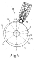
- FIG. 3 shows a sensor arrangement 10 similar to that shown in FIG. 1.
- the runway 14 has changeable, ramp-shaped diameter, the radial Change in diameter assigned to a specific angle of the shift drum can be.
- the individual rest points at gear positions G and N can also be assigned to singular diameters.
- the assignment to certain gear positions G, z. B. reverse, 1st, 2nd or 3rd gear and various intermediate neutral positions can be achieved.
- area 20, as already described in FIG. 2 does not become in practical operation drive through, so the position data there is not needed.
- the illustrated embodiments are only examples Realizations of the Invention.
- the invention is not based on the examples shown limited, more changes and training are possible.
- modifications of the sensor disk 11 are combined Acquisition of different position data in radial and axial directions is conceivable.
Abstract
Description
Die Erfindung bezieht sich auf eine Sensoranordnung zur Bestimmung der Schaltwalzenstellung einer Schaltwalze gemäß dem Oberbegriff des Patentanspruches 1.The invention relates to a sensor arrangement for determining the Shift drum position of a shift drum according to the preamble of Claim 1.
Aus dem Stand der Technik sind verschiedene Sensoranordnungen zur Bestimmung der Schaltstellung insbesondere einer Getriebesteuerung bekannt. So ist z. B. aus der DE 199 29 632 A1 eine Vorrichtung zur Stellungserfassung von zwei Achsbewegungen, insbesondere der Schaltstellung einer Getriebesteuerung bekannt, bei der auf einer Welle mindestens eine Nockenbahn ausgebildet ist, an der ein Fortsatz eines Tasthebels entlang gleitet, wobei die Bewegung des Fortsatzes mit Hilfe eines Sensors in ein Ausgangssignal umgewandelt wird. Dabei befinden sich in Achsrichtung der Welle gesehen zu beiden Seiten einer ersten Nockenbahn mit kreisförmig verlaufender Oberfläche eine zweite und eine dritte Nockenbahn, wobei diese jeweils in Umfangsrichtung der Welle gesehen hintereinander Abschnitte mit unterschiedlicher Ausbildung aufweisen. Es wird dabei über ein Federelement ein Tasthebel auf die Mantelfläche des Nockens gedrückt, der eine kugelförmig ausgebildete Spitze aufweist. Über diesen Tasthebel werden nun während der Bewegung der Welle in axialer Richtung und in Drehrichtung diese beiden Bewegungen ständig vom Tasthebel mit dessen Spitze nachverfolgt und darüber die Schaltstellung ermittelt. Nachteilig ist hier, dass die Vorrichtung eine schwierig zu fertigende Geometriebahn aufweist, und, da die Welle auch eine Bewegung in axialer Richtung ausführt, dass der Tasthebel aufwendig gelagert werden muß.Various sensor arrangements for determination are from the prior art the shift position, in particular a transmission control known. So z. B. from DE 199 29 632 A1 discloses a device for detecting the position of two Axis movements, especially the shift position of a transmission control known in which at least one cam track is formed on a shaft, on the an extension of a probe lever slides along, the movement of the extension is converted into an output signal using a sensor. Doing so seen in the axial direction of the shaft on both sides of a first cam track with a circular surface, a second and a third cam track, each of these sections viewed in the circumferential direction of the shaft one behind the other with different training. It is a spring element Tactile lever pressed onto the outer surface of the cam, which is a spherical trained tip. This button will now be used during the Movement of the shaft in the axial direction and in the direction of rotation of these two Movements are constantly tracked by the feeler lever with its tip and above that Switch position determined. The disadvantage here is that the device is difficult to has manufacturing geometry path, and, since the shaft also a movement in axial direction that the probe lever must be stored consuming.
Aus der DE 199 20 440 A1 ist weiterhin ein Stufengetriebe für ein Kraftfahrzeug mit einer Mehrzahl von Radsätzen entsprechend einer Mehrzahl von Gängen und mit einer drehbaren Schaltwalze bekannt, die wenigstens eine Umfangsnut aufweist, in der ein axial verschiebliches Führungselement geführt ist, das mit Mitteln zum Einund Auslegen von wenigstens einem der Gänge gekoppelt ist. Es ist dabei eine weitere drehbare Schaltwalze vorgesehen, die wenigstens eine weitere Umfangsnut aufweist, in der ein weiteres axial verschiebliches Führungselement geführt ist, das mit Mitteln zum Ein- bzw. Auslegen von wenigstens einem anderen der Gänge gekoppelt ist. Bei dieser Anordnung kann die Steuerung bzw. Betätigung für die Schaltwalzen unterschiedliche Ausgestaltung aufweisen. So können dabei z.B. Kurvenscheiben vorgesehen sein, die mit den Schaltwalzen kraft- oder formschlüssig verbunden oder einstückig hiermit ausgeführt sind. Dabei kann der Umfang der Kurvenscheiben in Winkelbereichen, die den Schaltstellungen von einem der Gänge entsprechen, mit einem größeren Radius versehen sein als in den Winkelbereichen entsprechend den neutralen Schaltstellungen; es umfassen also dabei die Kurvenscheiben radial vorstehende Winkelbereiche, die den Schaltstellungen der Gänge entsprechen, und radial zurückversetzte Winkelbereiche, die den neutralen Schaltstellungen entsprechen. Bei dieser Anordnung ist ebenfalls die sehr genaue und variable Steuerung bzw. Betätigung der jeweiligen Schaltstellung von Vorteil, nachteilig ist jedoch hier, daß diese Vorrichtung nicht zuläßt, allein aus der Stellung der Kurvenscheibe die Schaltstellung zu bestimmen.From DE 199 20 440 A1 there is also a multi-step transmission for a motor vehicle a plurality of wheel sets corresponding to a plurality of gears and with a rotatable shift drum known, which has at least one circumferential groove, in which is guided an axially displaceable guide element, which means for Einund Laying out at least one of the gears is coupled. It is one further rotatable shift drum provided, the at least one further circumferential groove has, in which a further axially displaceable guide element is guided, the with means for inserting or removing at least one other of the aisles is coupled. With this arrangement, the control for the Shift drums have different designs. For example, Cam discs are provided, which are non-positive or positive with the shift drums connected or made in one piece herewith. The scope of the Cam discs in angular ranges that indicate the shift positions of one of the gears correspond, be provided with a larger radius than in the angular ranges according to the neutral switch positions; it includes the Cam radially protruding angular ranges that the switching positions of the Gears correspond to, and radially recessed angular ranges that correspond to the neutral Switch positions correspond. This arrangement is also very precise and variable control or actuation of the respective switching position is advantageous, the disadvantage here, however, is that this device does not allow, alone from the position to determine the switching position of the cam.
Aus der EP 10 094 253 A2 ist eine Schaltungsanordnung mit einer Steuereinrichtung bekannt, bei der die verschiedenen Wellenstellungen der Ein- und Ausgangswellen eines Übertragungsgetriebes mittels verschiedener Sensorelemente erfaßt werden, die ihrerseits über eine elektronische Steuerung weiterverarbeitet werden. Die Ausführung der Anordnung dient dabei insbesondere zur Gewichtsreduzierung und zur Erhöhung der Zuverlässigkeit.EP 10 094 253 A2 describes a circuit arrangement with a control device known, in which the different shaft positions of the input and output shafts a transmission gear can be detected by means of various sensor elements, which in turn are processed via an electronic control. The Execution of the arrangement is used in particular for weight reduction and to increase reliability.
Aus der DE 43 14 952 A1 ist schließlich eine Vorrichtung zur Erfassung der Gangstellung eines Schaltgetriebes bekannt, dessen Getriebestufen mittels einer sowohl um ihre Achse drehbar als auch in Richtung ihrer Achse verschiebbar in einem Gehäuse des Schaltgetriebes gelagerten Schaltwelle schaltbar sind unter Verwendung von digitalen Schaltelementen. Es ist dabei eine Kombination von digitalen und analogen Schaltelementen vorgesehen, derart, daß für die Erfassung der Gassen digitale und für die Erfassung der Gänge analoge Schaltelemente vorgesehen sind. Es kann dabei das analoge Schaltelement unterschiedliche Ausbildungen aufweisen, es kann z.B. als Drehwinkelsensor oder auch als Wegsensor ausgebildet sein.Finally, DE 43 14 952 A1 describes a device for detecting the Gear position of a manual transmission known, the gear stages by means of a both rotatable about its axis and displaceable in the direction of its axis in a shaft of the gearbox mounted shift shaft are switchable under Use of digital switching elements. It is a combination of digital and analog switching elements are provided, such that for detection of the alleys digital and for the detection of the gears analog switching elements are provided. The analog switching element can be different Have training, e.g. as a rotation angle sensor or as Travel sensor be formed.
Ausgehend von diesen bekannten Sensoranordnungen zur Bestimmung der Schaltstellung insbesondere einer Getriebesteuerung liegt der Erfindung die Aufgabe zugrunde, eine Sensoranordnung zu entwickeln, die einen einfacheren Aufbau als die bekannten Sensoranordnungen aufweist.Based on these known sensor arrangements for determining the Switch position, in particular a transmission control, the invention is the The task is to develop a sensor arrangement that is simpler Structure than the known sensor arrangements.
Die Aufgabe wird erfindungsgemäß dadurch gelöst, indem die Ablaufbahn zumindest teilweise Bereiche für Gangstellungen, Neutralstellungen und Schaltungsabschnitte aufweist, wobei ein Schaltungsabschnitt jeweils zwischen einer Gangstellung und einer Neutralstellung angeordnet ist, und wobei die von der Abtasteinrichtung zu erfassenden Positionsdaten von Gangstellungen und Neutralstellungen von den Positionsdaten der Schaltungsabschnitte unterschiedlich sind, und die Positionsdaten der Schaltungsabschnitte, die einer Gangstellung oder einer Neutralstellung direkt benachbart sind, untereinander unterschiedlich sind.According to the invention, the object is achieved in that the runway at least some areas for gear positions, neutral positions and gear sections has, wherein a circuit section between a gear position and a neutral position is arranged, and which from the scanner to position data of gear positions and neutral positions of the Position data of the circuit sections are different, and the Position data of the circuit sections that a gear position or Neutral position are directly adjacent, are different from each other.
Auf diese Weise wird erstmalig mit einfachen Mitteln die Möglichkeit geschaffen, daß die Sensorscheibe nicht nur die einzelnen Schaltstellungen, d.h. die Gangstellungen G, die Neutralstellungen N und eine beliebige Referenzneutralstufe nN als Rastpunkt erkennt, sondern daß insbesondere auch gleichzeitig die Bereiche zwischen den Schaltabschnitten NG und GN aufgrund der Sensorstellung und der Drehrichtung erkannt wird, ob die nächste Schaltstellung Neutral oder ein Gang ist. Die kombinierte Erfassung der Positionsdaten über eine einzige Sensorscheibe, ohne axiale Verschiebung von Abtasteinrichtung oder Sensorscheibe, führt zu einer erheblichen Vereinfachung der Herstellung der Sensoranordnung bzw. ermöglicht es, einfachere Sensorelemente zu verwenden. Die Anordnung ermöglicht dabei trotzdem eine den Anforderungen vollkommen genügende Bestimmung der Schaltstellung und damit Kontrolle der Schaltwalze.In this way, the possibility is created for the first time with simple means that the sensor disc not only the individual switching positions, i.e. the gear positions G, the neutral positions N and any reference neutral level nN as a rest point recognizes, but in particular that the areas between the Switching sections NG and GN due to the sensor position and the direction of rotation it is recognized whether the next shift position is neutral or a gear. The Combined acquisition of position data via a single sensor disc, without axial displacement of the scanning device or sensor disk leads to a considerable simplification of the manufacture of the sensor arrangement or enables easier to use sensor elements. The arrangement enables nevertheless a determination of the switching position that fully meets the requirements and thus control of the shift drum.
In einer vorteilhaften Ausgestaltung der Erfindung weist die Ablaufbahn an zumindest einer Gangstellung oder Neutralstellung eine Rastnut auf und die Abtasteinrichtung wird mittels geeigneter Element auf die Ablaufbahn gedrückt. Damit wird die Funktionalität der Sensoranordnung von Sensorscheibe und Abtastsystem um die Funktion eines mechanisiertes Rastsystem, wie es z. B. aus Handschaltgetrieben bekannt ist, erweitert. Der mit der Ablaufbahn zusammenwirkende Abtastkopf bewerkstelligt durch den Andruck der Abtasteinrichtung auf die Ablaufbahn die Rastung in den Schaltstellungen Gang oder Neutral.In an advantageous embodiment of the invention, the runway has at least a notch in a gear position or neutral position and the scanning device is pressed onto the runway by means of a suitable element. With that the Functionality of the sensor arrangement of sensor disk and scanning system around the Function of a mechanized locking system, such as. B. from manual transmissions is known, expanded. The scanning head interacting with the trajectory accomplished by pressing the scanner on the runway Locking in the gear positions neutral or gear.
In einer weiteren erfinderischen Ausführung weist die Ablaufbahn im Bereich eines Schaltungsabschnittes veränderliche Positionsdaten auf. Dies kann z. B. bedeuten, daß der Schaltungsabschnitt rampenförmig bezüglich der zu messenden Positionsdaten ausgeführt ist, wodurch den Positionsdaten eine eindeutige Stellung der Sensorscheibe zugeordnet werden kann. Dabei können einzelne Schaltungsabschnitte die jeweils gleichen veränderlichen Positionsdaten aufweisen, oder aber, jeder Schaltungsabschnitt weist eigene, singuläre Positionsdaten auf. Auch ist jede Kombination möglich, z. B. kann ein Teil der Schaltungsabschnitte einen gleichen Verlauf der Positionsdaten aufweisen, ein anderer Teil einen anderen Verlauf der Positionsdaten.In a further inventive embodiment, the runway has a Circuit section variable position data. This can e.g. B. mean that the circuit section is ramped with respect to that to be measured Position data is executed, which gives the position data a unique position can be assigned to the sensor disc. Individuals can Circuit sections each have the same variable position data, or else, each circuit section has its own, unique position data. Any combination is also possible, e.g. B. can be part of the circuit sections have the same course of the position data, another part another Course of the position data.
Vorteilhaft weist die Ablaufbahn unterschiedliche Positionsdaten zwischen den Schaltstellungen von Gangstellungen und den Schaltstellungen von Neutralstellungen auf. Damit ist sofort erkennbar, ob ein Gang eingelegt ist oder ob sich das Getriebe in Neutral befindet.The runway advantageously has different position data between the Shift positions of gear positions and the shift positions of Neutral positions. This makes it immediately recognizable whether a gear is engaged or not the transmission is in neutral.
Weiterhin kann die Ablaufbahn unterschiedliche Positionsdaten zumindest für einzelne Gangstellungen aufweisen. Damit lässt sich aus den Positionsdaten sofort der eingelegte Gang bestimmen. Furthermore, the runway can have different position data at least for have individual gear positions. It can be used immediately from the position data determine the gear engaged.
Weiterhin kann die Ablaufbahn unterschiedliche Positionsdaten zumindest für einzelne Neutralstellungen aufweisen. Damit lässt sich aus den Positionsdaten sofort bestimmen, zwischen welchen Gängen sich die Schaltwalze in Neutral befindet. Insbesondere für eine Referenzneutral ist dies erforderlich. Es gibt eine Referenzneutralstellung, z. B. zwischen einem Vorwärtsgang und einem Rückwärtsgang, die eigene Positionsdaten aufweist, und die somit sofort erkannt werden kann. Ein Anwendung dafür ist die Neutralstellung des Getriebes, z. B. beim Anlassen eines Motors, wenn noch keine Schaltung erfolgte. Aus dieser Position heraus erfolgen dann die erste Schaltung.Furthermore, the runway can have different position data at least for have individual neutral positions. It can be used immediately from the position data determine between which gears the shift drum is in neutral. This is particularly necessary for reference neutral. There is a Reference neutral position, e.g. B. between a forward gear and a Reverse gear, which has its own position data, and thus immediately recognized can be. One application for this is the neutral position of the transmission, e.g. B. at Starting an engine if there is no shift. From this position the first switching then takes place.
In einer bevorzugten Ausführung weist die Sensorscheibe zur Erzeugung unterschiedlicher Positionsdaten in radialer Richtung unterschiedliche Durchmesser entlang ihrer Laufbahn auf. Dies entspricht einer im Umfang der Sensorscheibe angeordneten Laufbahn, die überwiegend in radialer Richtung von der Abtasteinrichtung abgetastet wird. Die Umfangsänderungen werden als Positionsdaten registriert und können entsprechend der Sensorscheibenstellung zugeordnet werden.In a preferred embodiment, the sensor disk has the generation different position data in the radial direction different diameters along their careers. This corresponds to one in the circumference of the sensor disk arranged career, which is predominantly in the radial direction from the Scanning device is scanned. The changes in scope are considered Position data registered and can according to the sensor disc position be assigned.
In einer weiteren Ausführung weist die Sensorscheibe zur Erzeugung unterschiedlicher Positionsdaten in axialer Richtung eine Laufbahn auf, die, in axialer Richtung der Sensorscheibenachse gesehen, nicht eben ist. Dies entspricht einer Anordnung der Abtasteinrichtung in axialer Richtung, d. h. das Abtastsystem erfasst an der Stirnseite der Sensorscheibe die axiale Unebenheit und ordnet diese Positionsdaten einer Sensorscheibenstellung zu. Natürlich ist auch eine Kombination von axialer Positionsdatenbestimmung und radialer Positionsdatenbestimmung, wie im vorherigen Absatz beschrieben, möglich. Sinnvollerweise kommen dann jedoch mindestens zwei Abtasteinrichtungen zum Einsatz.In a further embodiment, the sensor disk has the generation different position data in the axial direction on a track that, in Axial direction of the sensor disc axis seen, is not flat. This matches with an arrangement of the scanning device in the axial direction, d. H. the scanning system detects the axial unevenness on the face of the sensor disk and arranges it Position data of a sensor disc position. Of course there is also a combination of axial position data determination and radial position data determination, such as described in the previous paragraph, possible. Then it makes sense to come at least two scanning devices are used.
In einer weiteren bevorzugten Ausführung weist die Abtasteinrichtung zur Abtastung der Ablaufbahn der Sensorscheibe eine drehbar gelagerte Kugel auf. Die Kugel als Abtastkopf verringert die Reibung zwischen Abtasteinrichtung und Ablaufbahn, was vor allem bei der Verwendung der Sensoranordnung als Rastsystem eine sichere Schaltung und genaue Messung im Bereich der Rastnuten ermöglicht. Prinzipiell aber kann die Abtasteinrichtung jeden bekannten Abtastkopf zum Abtasten von Oberflächen aufweisen, ist also nicht auf eine Kugel als Abtastkopf beschränkt.In a further preferred embodiment, the scanning device has for scanning the ball of the sensor disc has a rotatably mounted ball. The ball as Scanning head reduces the friction between the scanning device and the track, what a safe one especially when using the sensor arrangement as a locking system Switching and precise measurement in the area of the locking grooves possible. in principle but the scanner can use any known scanner head for scanning Having surfaces, is not limited to a ball as a scanning head.
Bevorzugt weist die Abtasteinrichtung einen als Hall- Element ausgebildeten Sensor auf. Dadurch kann aus der Bewegung der Abtasteinrichtung, welche aus der Änderung der Positionsdaten resultiert, sehr genau die relative Verschiebung und damit die Positionsdaten bestimmt werden. Bei dem als Hall-Element ausgeführten Sensor wird vorwiegend eine lineare Verschiebung der Abtasteinrichtung gemessen. Es versteht sich von selbst, das auch jede andere Verschiebung oder Verdrehung der Abtasteinrichtung zur Bestimmung der Positionsdaten herangezogen und mittels geeigneter Sensoren erfasst werden kann.The scanning device preferably has a sensor designed as a Hall element on. As a result, the movement of the scanning device, which results from the Change in position data results in very accurate relative displacement and so that the position data can be determined. In the case of the Hall element The sensor mainly measures a linear displacement of the scanning device. It goes without saying that any other shift or twist the scanning device for determining the position data and by means of suitable sensors can be detected.
Weitere vorteilhafte Ausgestaltungen der Erfindung sind den Zeichnungen zu entnehmen. Es zeigen:
- Fig. 1
- eine Seitenansicht einer ersten Ausführungsform der erfindungsgemäßen Sensoranordnung im Schnitt,
- Fig. 2
- eine Querschnittsansicht der ersten Ausführungsform der erfindungsgemäßen Sensoranordnung,
- Fig. 3
- eine Querschnittsansicht einer zweiten Ausführungsform der erfindungsgemäßen Sensoranordnung,
- Fig. 1
- 2 shows a sectional side view of a first embodiment of the sensor arrangement according to the invention,
- Fig. 2
- 2 shows a cross-sectional view of the first embodiment of the sensor arrangement according to the invention,
- Fig. 3
- 2 shows a cross-sectional view of a second embodiment of the sensor arrangement according to the invention,
In Figur 1 ist eine erfindungsgemäße Sensoranordnung 10 dargestellt. Die
Sensoranordnung 10 weist eine mit der Schaltwalze in Wirkverbindung stehende
Sensorscheibe 11 mit der Ablaufbahn 14 auf. Die Sensoranordnung 10 weist
weiterhin eine die Ablaufbahn 14 der Sensorscheibe 11 kontinuierlich abgreifende,
federbelastete Abtasteinrichtung 12 auf, wobei eine drehbar gelagerte Kugel 15
direkt auf der Ablaufbahn 14 abläuft.A
Die Abtasteinrichtung 12 ist in einem fest am nicht dargestellten Getriebe befestigten
Abtastgehäuse 20 verschiebbar gelagert, wobei die Bewegungsrichtung
überwiegend in radialer Richtung der Sensorscheibe 11 orientiert ist. Die Feder 16,
die auf einer Seite im Abtastgehäuse 20 gelagert ist, drückt mit ihrer anderen Seite
die Abtasteinrichtung 12 und damit die Kugel 15 auf die Ablaufbahn 14. Am der
Kugel 5 entgegengesetzten Ende ist auf der Abtasteinrichtung ein Magnet 13
angeordnet, der Teil des Hall-Element ausgebildeten Sensors 19 ist. Der Sensor 19
erfaßt die Positionsdaten der Abtasteinrichtung 12 und wandelt diese in ein
elektrisches Signal um.The
In Figur 2 ist die Querschnittsansicht der erfindungsgemäßen Sensoranordnung gezeigt. Entlang der Ablaufbahn 14 ist die Sensorscheibe 11 zur kombinierten Erfassung von auf Schaltungsabschnitte GN, NG der Schaltwalze bezogene Positionsdaten und von auf präzise Schaltstellungen G, N, nN der Schaltwalze bezogene Positionsdaten ausgebildet. Hierbei bedeuten:
- N:
- Neutralstellung, Schaltstellung, bei der sich das Getriebe in Neutral befindet;
- nN:
- Referenzneutralstellung, eine bestimmte, einmalige Schaltstellung, bei der sich das Getriebe in Neutral befindet, als Referenz benutzt, bevorzugt zwischen einem Vorwärtsgangstellung und einer Rückwärtsgangstellung angeordnet;
- G:
- Gangstellung, Schaltstellung bei der ein Gang im Getriebe eingelegt ist, z. B. Rückwärtsgang, 1. 2. oder 3. Gang usw.;
- NG:
- Schaltungsabschnitt zwischen einer Neutralstellung N und einer Schaltstellung G, wobei die Neutralstellung N nur in eine erste Drehrichtung der Schaltwalze erreicht wird, die Gangstellung G dagegen in eine zweite, entgegengesetzte Drehrichtung;
- GN:
- Schaltungsabschnitt zwischen einer Neutralstellung N und einer Schaltstellung G, wobei - entgegengesetzt zu NG - die Neutralstellung N nur in die zweite Drehrichtung der Schaltwalze erreicht wird, und die Gangstellung G dagegen in die erste, entgegengesetzte Drehrichtung.
- N:
- Neutral position, shift position in which the transmission is in neutral;
- nN:
- Reference neutral position, a certain, unique shift position, in which the transmission is in neutral, used as a reference, preferably arranged between a forward gear position and a reverse gear position;
- G:
- Gear position, gear position in which a gear is engaged in the transmission, e.g. B. reverse gear, 1st 2nd or 3rd gear, etc .;
- NG:
- Shifting section between a neutral position N and a shift position G, the neutral position N being reached only in a first direction of rotation of the shift drum, the gear position G in contrast, in a second, opposite direction of rotation;
- GN:
- Shifting section between a neutral position N and a shift position G, whereby - contrary to NG - the neutral position N is only reached in the second direction of rotation of the shift drum, and the gear position G in the first, opposite direction of rotation.
Die Sensorscheibe 11 weist zur kombinierten Erfassung der unterschiedlichen
Positionsdaten zwischen den Schaltabschnitten NG und GN unterschiedliche
Durchmesser auf. Die Schaltstellungen G, N und nN, die als Schaltnuten ausgeführt
sind, weisen ebenfalls jeweils unterschiedliche Durchmesser auf, die sich ebenfalls
von den Durchmessern der Schaltabschnitte NG und GN unterscheiden. Durch
Auswertung des Stellungssignals des Sensors 19 wird die augenblickliche Stellung
der Sensorscheibe 11 erkannt. Weiterhin kann aus dem Stellungssignal abgeleitet
werden, ob in Drehrichtung eine Neutralstellung oder eine Gangstellung folgt, da,
abhängig von NG oder GN, in Drehrichtung nur G oder N bzw. nN als nächste
Schaltstellung folgen können. Umgekehrt kann auch aufgrund der Auswertung bei
der Bewegung aus einer Schaltstellung G, N oder nN die Drehrichtung der
Schaltwalze ermittelt werden, da bei einer Drehrichtung aus G z. B. immer NG, aus N
dann aber GN folgen muß.The
Im Bereich 20 der Abtastbahn 14 liegt weder ein Schaltungsabschnitt GN noch NG
vor. Der Bereich 20 wird im Betrieb praktisch nicht durchfahren, da die Schaltwalze in
diesem Beispiel nur eine Drehung von kleiner 360° ausführt. Die beiden dem Bereich
20 benachbarten Gangstellungen G stellen damit jeweils die beiden Endstellungen
der Schaltwalzendrehung dar.Neither a circuit section GN nor NG lies in the
Bei einer weiteren Ausgestaltung der Erfindung weisen die Raststellungen von G bzw. von N auch untereinander unterschiedliche Durchmesser auf, so daß auch z. B. die 1. Gangstufe, die 3. Gangstufe, Neutral zwischen 1. und 2. Gang usw. direkt erkannt werden können.In a further embodiment of the invention, the locking positions of G or of N also different diameters from each other, so that z. B. 1st gear, 3rd gear, neutral between 1st and 2nd gear etc. directly can be recognized.
Die Sensorscheibe 11 weist im Bereich der Rastnuten an den Gangstellungen G und
den Neutralstellungen N einen radial zurückversetzten, entgegengesetzt
kreisbogenförmigen Teilbereich 17 auf. Dadurch werden die einzelnen
Schaltstellungen G, N auf der Sensorscheibe 11 genau festgelegt, was für die
Messung der Positionsdaten mit hoher Präzision in den einzelnen Schaltstellungen
G, N von Bedeutung ist, da die mit der Sensorscheibe in Verbindung stehende
Schaltwalze durch das federbelastete Abtasteinrichtung 12 mittels der Kugel 15
mechanisch in Stellung gehalten und gerastet wird. Somit wird eine sichere,
reproduzierbare Rastung in den Schaltstellungen erzielt.The
In Figur 3 ist eine ähnliche Sensoranordnung 10 wie in Figur 1 dargestellt. Lediglich
die Sensorscheibe 11 unterscheidet sich bezüglich der Durchmesser an der
Ablaufbahn 14: In den Bereichen zwischen nN, N und G weist die Ablaufbahn 14
veränderbare, rampenförmig verlaufende Durchmesser auf, wobei die radiale
Änderung des Durchmessers einem bestimmten Winkel der Schaltwalze zugeordnet
werden kann. Die einzelnen Rastpunkte an den Gangstellungen G und N können
ebenfalls singulären Durchmessern zugeordnet werden. Somit kann die Zuordnung
zu bestimmten Gangstellungen G, z. B. Rückwärts-, 1.-, 2.- oder 3.-Gang und
verschiedenen dazwischenliegenden Neutralpositionen erreicht werden. Auch hier
wird der Bereich 20, wie bereits in Figur 2 beschrieben, im praktischen Betrieb nicht
durchfahren, somit werden die dortigen Positionsdaten nicht gebraucht.FIG. 3 shows a
Wie bereits erwähnt, sind die dargestellten Ausführungsformen nur beispielsweise
Verwirklichungen der Erfindung. Die Erfindung ist nicht auf die gezeigten Beispiele
beschränkt, es sind vielmehr noch weitere Abänderungen und Ausbildungen möglich.
So sind insbesondere Abwandlungen der Sensorscheibe 11 zur kombinierten
Erfassung unterschiedlichen Positionsdaten in radialer und axialer Richtung denkbar.As already mentioned, the illustrated embodiments are only examples
Realizations of the Invention. The invention is not based on the examples shown
limited, more changes and training are possible.
In particular, modifications of the
Claims (10)
dadurch gekennzeichnet, daß
characterized in that
dadurch gekennzeichnet, daß
die Ablaufbahn (14) an zumindest einer Gangstellung (G) oder Neutralstellung (N) eine Rastnut (17) aufweist, und die Abtasteinrichtung (12) mittels geeigneter Element auf die Ablaufbahn gedrückt wird. Sensor arrangement according to claim 1,
characterized in that
the runway (14) has a latching groove (17) in at least one gear position (G) or neutral position (N), and the scanning device (12) is pressed onto the runway by means of a suitable element.
dadurch gekennzeichnet, daß
die Ablaufbahn (14) im Bereich eines Schaltungsabschnittes (GN, NG) veränderliche Positionsdaten aufweist.Sensor arrangement according to claim 1 or 2,
characterized in that
the runway (14) has variable position data in the area of a circuit section (GN, NG).
dadurch gekennzeichnet, daß
die Ablaufbahn (14) unterschiedliche Positionsdaten zwischen den Schaltstellungen von Gangstellungen (G) und den Schaltstellungen von Neutralstellungen (N) aufweist.Sensor arrangement according to one of the preceding claims,
characterized in that
the runway (14) has different position data between the shift positions of gear positions (G) and the shift positions of neutral positions (N).
dadurch gekennzeichnet, daß
die Ablaufbahn (14) unterschiedliche Positionsdaten zumindest für einzelne Gangstellungen (G) aufweist.Sensor arrangement according to one of the preceding claims,
characterized in that
the runway (14) has different position data at least for individual gear positions (G).
dadurch gekennzeichnet, daß
die Ablaufbahn (14) unterschiedliche Positionsdaten zumindest für einzelne Neutralstellungen (N, nN) aufweist.Sensor arrangement according to one of the preceding claims,
characterized in that
the runway (14) has different position data at least for individual neutral positions (N, nN).
dadurch gekennzeichnet, daß
die Sensorscheibe (11) zur Erzeugung unterschiedlicher Positionsdaten in radialer Richtung unterschiedliche Durchmesser entlang ihrer Laufbahn (14) aufweist. Sensor arrangement according to one of the preceding claims,
characterized in that
the sensor disk (11) has different diameters along its track (14) in order to generate different position data in the radial direction.
dadurch gekennzeichnet, daß
die Sensorscheibe (11) zur Erzeugung unterschiedlicher Positionsdaten in axialer Richtung eine Laufbahn (14) aufweist, die, in axialer Richtung der Sensorscheibenachse gesehen, nicht eben ist.Sensor arrangement according to one of the preceding claims,
characterized in that
the sensor disk (11) has a raceway (14) for generating different position data in the axial direction which, when viewed in the axial direction of the sensor disk axis, is not flat.
dadurch gekennzeichnet, daß
die Abtasteinrichtung (12) zur Abtastung der Ablaufbahn (14) der Sensorscheibe (2) eine drehbar gelagerte Kugel (15) aufweist.Sensor arrangement according to one of the preceding claims,
characterized in that
the scanning device (12) for scanning the runway (14) of the sensor disc (2) has a rotatably mounted ball (15).
dadurch gekennzeichnet, daß
die Abtasteinrichtung (12) einen als Hall- Element ausgebildeten Sensor (19) aufweist.Sensor arrangement according to one of the preceding claims,
characterized in that
the scanning device (12) has a sensor (19) designed as a Hall element.
Priority Applications (3)
| Application Number | Priority Date | Filing Date | Title |
|---|---|---|---|
| DE50204390T DE50204390D1 (en) | 2002-03-26 | 2002-03-26 | Sensor arrangement for determining the shift drum position |
| EP02100293A EP1350991B1 (en) | 2002-03-26 | 2002-03-26 | Sensor arrangement for determining the position of a shift drum |
| US10/249,186 US6730864B2 (en) | 2002-03-26 | 2003-03-20 | Sensor arrangement for determining selector drum position |
Applications Claiming Priority (1)
| Application Number | Priority Date | Filing Date | Title |
|---|---|---|---|
| EP02100293A EP1350991B1 (en) | 2002-03-26 | 2002-03-26 | Sensor arrangement for determining the position of a shift drum |
Publications (2)
| Publication Number | Publication Date |
|---|---|
| EP1350991A1 true EP1350991A1 (en) | 2003-10-08 |
| EP1350991B1 EP1350991B1 (en) | 2005-09-28 |
Family
ID=27838127
Family Applications (1)
| Application Number | Title | Priority Date | Filing Date |
|---|---|---|---|
| EP02100293A Expired - Lifetime EP1350991B1 (en) | 2002-03-26 | 2002-03-26 | Sensor arrangement for determining the position of a shift drum |
Country Status (3)
| Country | Link |
|---|---|
| US (1) | US6730864B2 (en) |
| EP (1) | EP1350991B1 (en) |
| DE (1) | DE50204390D1 (en) |
Cited By (10)
| Publication number | Priority date | Publication date | Assignee | Title |
|---|---|---|---|---|
| DE102005034864A1 (en) * | 2005-07-26 | 2007-02-01 | Knorr-Bremse Systeme für Nutzfahrzeuge GmbH | Actuator for a transmission |
| FR2904395A1 (en) * | 2006-07-31 | 2008-02-01 | Peugeot Citroen Automobiles Sa | Manual or driven gearbox state determining method for vehicle i.e. passenger car, involves using ball indexer that is provided with ball position sensor which is coupled to management unit |
| WO2008017520A1 (en) | 2006-08-05 | 2008-02-14 | Schaeffler Kg | Sensor arrangement |
| WO2008107290A1 (en) * | 2007-03-08 | 2008-09-12 | Schaeffler Kg | Controller drum |
| WO2008122501A1 (en) | 2007-04-07 | 2008-10-16 | Schaeffler Kg | Sensor arrangement for detecting the gear position of a transmission, and transmission having the sensor arrangement |
| WO2009021795A1 (en) * | 2007-08-10 | 2009-02-19 | Schaeffler Kg | Apparatus for determination of a switch position of a mechanical system |
| WO2010046218A1 (en) * | 2008-10-24 | 2010-04-29 | Schaeffler Technologies Gmbh & Co. Kg | Sensor shift unit |
| WO2010069704A1 (en) * | 2008-12-19 | 2010-06-24 | Schaeffler Technologies Gmbh & Co. Kg | Method for detecting the position of a mobile switching element |
| EP2829772A1 (en) * | 2013-07-26 | 2015-01-28 | AISIN AI Co., Ltd. | Travel transmission apparatus |
| DE102013205071B4 (en) | 2013-03-22 | 2019-08-01 | Schaeffler Technologies AG & Co. KG | Switching device for a change-speed gearbox of a motor vehicle and linear roller bearing with a switching device |
Families Citing this family (17)
| Publication number | Priority date | Publication date | Assignee | Title |
|---|---|---|---|---|
| US7199316B2 (en) * | 2004-09-10 | 2007-04-03 | W.T. Storey, Inc. | Multifunction switch for operating a device in a sealed container |
| DE102005034865B4 (en) * | 2005-07-26 | 2012-03-22 | Knorr-Bremse Systeme für Nutzfahrzeuge GmbH | Actuator for a transmission |
| JP4890185B2 (en) * | 2006-09-29 | 2012-03-07 | 本田技研工業株式会社 | Vehicle transmission |
| JP4970099B2 (en) * | 2007-03-22 | 2012-07-04 | 本田技研工業株式会社 | Vehicle transmission |
| US20080264329A1 (en) * | 2007-04-27 | 2008-10-30 | Denso Corporation | Dial device and method for manufacturing the same |
| DE102008053196A1 (en) | 2008-10-24 | 2010-04-29 | Schaeffler Kg | Sensor switching unit for use in change speed gearbox of motor vehicle, has pressure sensors molded with plastic, and switching lock including locking element that is locked with locking contour and pre-stressed opposite to gear component |
| DE102008053194A1 (en) | 2008-10-24 | 2010-04-29 | Schaeffler Kg | Switching unit for determining and regulating gear speed settings, has gear component, particularly selector shaft, where signal evaluation unit is connected with resting element in electrically conducting manner |
| DE102009030823A1 (en) * | 2009-06-26 | 2011-01-20 | Koki Technik Transmission Systems Gmbh | Rastiervorrichtung for a shift shaft |
| JP2013252778A (en) * | 2012-06-06 | 2013-12-19 | Tokai Rika Co Ltd | Operating device and shift lever device |
| DE102013200658A1 (en) | 2013-01-17 | 2014-07-17 | Schaeffler Technologies Gmbh & Co. Kg | Switching device i.e. switching dome, for e.g. gear wheel change speed gearbox of hybrid vehicle, has sensor elements changing electric resistance by moving sensor section that is mechanically connected and/or coupled with part of device |
| DE202013004061U1 (en) | 2013-04-04 | 2013-06-14 | Schaeffler Technologies AG & Co. KG | Switching element of a Fahrzeuggangräderwechselgetriebes |
| KR101741441B1 (en) * | 2014-07-24 | 2017-05-30 | 삼성중공업 주식회사 | Automatic Painting Apparatus |
| DE102014019545A1 (en) | 2014-12-23 | 2016-06-23 | Daimler Ag | switching device |
| CN107627096A (en) * | 2017-10-10 | 2018-01-26 | 西安法士特汽车传动有限公司 | A kind of adjustable shifting block mechanism of feel in processing, adjustment and use |
| JP7159973B2 (en) * | 2019-05-22 | 2022-10-25 | トヨタ自動車株式会社 | Vehicle range switching device |
| DE102020126396B4 (en) | 2020-10-08 | 2023-10-26 | Schaeffler Technologies AG & Co. KG | Switching element and switching device with a switching element |
| JP2022158534A (en) * | 2021-04-02 | 2022-10-17 | 株式会社東海理化電機製作所 | Lever operation device |
Citations (8)
| Publication number | Priority date | Publication date | Assignee | Title |
|---|---|---|---|---|
| GB2240372A (en) * | 1990-01-25 | 1991-07-31 | Automotive Products Plc | A gear position sensor |
| DE4314952A1 (en) | 1993-05-06 | 1994-11-10 | Fichtel & Sachs Ag | Device for detecting the gear position of a manual transmission |
| DE19507621A1 (en) * | 1994-03-18 | 1995-09-21 | Volkswagen Ag | Vehicle switch lever operating sensor |
| EP0806591A1 (en) * | 1996-05-07 | 1997-11-12 | MAGNETI MARELLI S.p.A. | Device for detecting the position of a selector rod for carrying out an action of selecting and an action of engaging a gear in a vehicle gearbox |
| DE19920440A1 (en) | 1999-05-04 | 2000-11-16 | Getrag Getriebe Zahnrad | Discrete gearbox for motor vehicle has two rotatable change rollers with peripheral grooves for axially movable guide elements coupled to gear engaging or disengaging mechanisms |
| EP1063450A1 (en) * | 1999-06-25 | 2000-12-27 | Hydraulik-Ring GmbH | Position measuring and control device for vehicle gearbox |
| DE19929632A1 (en) | 1999-06-29 | 2001-01-18 | Bosch Gmbh Robert | Device for detecting the position of two axis movements |
| EP1094253A2 (en) | 1999-10-18 | 2001-04-25 | BorgWarner Inc. | Integrated shift motor and electronic controller |
Family Cites Families (3)
| Publication number | Priority date | Publication date | Assignee | Title |
|---|---|---|---|---|
| US4296394A (en) * | 1978-02-13 | 1981-10-20 | Ragheb A Kadry | Magnetic switching device for contact-dependent and contactless switching |
| US5304981A (en) * | 1988-04-29 | 1994-04-19 | Chrysler Corporation | Method of determining the driver selected operating mode of an automatic transmission system |
| ATE259725T1 (en) * | 1997-03-20 | 2004-03-15 | Delphi Tech Inc | STEERING STOCK MODULE WITH CENTRAL ELECTRICAL CONTROL UNIT AND AFTER RADIAL ASSEMBLY |
-
2002
- 2002-03-26 DE DE50204390T patent/DE50204390D1/en not_active Expired - Lifetime
- 2002-03-26 EP EP02100293A patent/EP1350991B1/en not_active Expired - Lifetime
-
2003
- 2003-03-20 US US10/249,186 patent/US6730864B2/en not_active Expired - Lifetime
Patent Citations (8)
| Publication number | Priority date | Publication date | Assignee | Title |
|---|---|---|---|---|
| GB2240372A (en) * | 1990-01-25 | 1991-07-31 | Automotive Products Plc | A gear position sensor |
| DE4314952A1 (en) | 1993-05-06 | 1994-11-10 | Fichtel & Sachs Ag | Device for detecting the gear position of a manual transmission |
| DE19507621A1 (en) * | 1994-03-18 | 1995-09-21 | Volkswagen Ag | Vehicle switch lever operating sensor |
| EP0806591A1 (en) * | 1996-05-07 | 1997-11-12 | MAGNETI MARELLI S.p.A. | Device for detecting the position of a selector rod for carrying out an action of selecting and an action of engaging a gear in a vehicle gearbox |
| DE19920440A1 (en) | 1999-05-04 | 2000-11-16 | Getrag Getriebe Zahnrad | Discrete gearbox for motor vehicle has two rotatable change rollers with peripheral grooves for axially movable guide elements coupled to gear engaging or disengaging mechanisms |
| EP1063450A1 (en) * | 1999-06-25 | 2000-12-27 | Hydraulik-Ring GmbH | Position measuring and control device for vehicle gearbox |
| DE19929632A1 (en) | 1999-06-29 | 2001-01-18 | Bosch Gmbh Robert | Device for detecting the position of two axis movements |
| EP1094253A2 (en) | 1999-10-18 | 2001-04-25 | BorgWarner Inc. | Integrated shift motor and electronic controller |
Cited By (16)
| Publication number | Priority date | Publication date | Assignee | Title |
|---|---|---|---|---|
| DE102005034864B4 (en) * | 2005-07-26 | 2008-11-27 | Knorr-Bremse Systeme für Nutzfahrzeuge GmbH | Actuator for a transmission |
| WO2007012460A1 (en) * | 2005-07-26 | 2007-02-01 | Knorr-Bremse Systeme für Nutzfahrzeuge GmbH | Adjusting device for a transmission |
| DE102005034864A1 (en) * | 2005-07-26 | 2007-02-01 | Knorr-Bremse Systeme für Nutzfahrzeuge GmbH | Actuator for a transmission |
| CN101258341B (en) * | 2005-07-26 | 2012-06-27 | 克诺尔商用车制动系统有限公司 | Adjusting device for a transmission |
| US7543515B2 (en) | 2005-07-26 | 2009-06-09 | Knorr-Bremse Systeme Fuer Nutzfahrzeuge Gmbh | Adjusting device for a transmission |
| FR2904395A1 (en) * | 2006-07-31 | 2008-02-01 | Peugeot Citroen Automobiles Sa | Manual or driven gearbox state determining method for vehicle i.e. passenger car, involves using ball indexer that is provided with ball position sensor which is coupled to management unit |
| WO2008015351A1 (en) * | 2006-07-31 | 2008-02-07 | Peugeot Citroën Automobiles SA | Method for determining the dead center state of a motor vehicle transmission |
| WO2008017520A1 (en) | 2006-08-05 | 2008-02-14 | Schaeffler Kg | Sensor arrangement |
| WO2008107290A1 (en) * | 2007-03-08 | 2008-09-12 | Schaeffler Kg | Controller drum |
| WO2008122501A1 (en) | 2007-04-07 | 2008-10-16 | Schaeffler Kg | Sensor arrangement for detecting the gear position of a transmission, and transmission having the sensor arrangement |
| CN101652584B (en) * | 2007-04-07 | 2015-09-23 | 舍弗勒技术股份两合公司 | Detect the detector assembly of the gear of speed changer and there is the speed changer of detector assembly |
| WO2009021795A1 (en) * | 2007-08-10 | 2009-02-19 | Schaeffler Kg | Apparatus for determination of a switch position of a mechanical system |
| WO2010046218A1 (en) * | 2008-10-24 | 2010-04-29 | Schaeffler Technologies Gmbh & Co. Kg | Sensor shift unit |
| WO2010069704A1 (en) * | 2008-12-19 | 2010-06-24 | Schaeffler Technologies Gmbh & Co. Kg | Method for detecting the position of a mobile switching element |
| DE102013205071B4 (en) | 2013-03-22 | 2019-08-01 | Schaeffler Technologies AG & Co. KG | Switching device for a change-speed gearbox of a motor vehicle and linear roller bearing with a switching device |
| EP2829772A1 (en) * | 2013-07-26 | 2015-01-28 | AISIN AI Co., Ltd. | Travel transmission apparatus |
Also Published As
| Publication number | Publication date |
|---|---|
| EP1350991B1 (en) | 2005-09-28 |
| US20030184428A1 (en) | 2003-10-02 |
| DE50204390D1 (en) | 2006-02-09 |
| US6730864B2 (en) | 2004-05-04 |
Similar Documents
| Publication | Publication Date | Title |
|---|---|---|
| EP1350991B1 (en) | Sensor arrangement for determining the position of a shift drum | |
| EP0794362B1 (en) | Gear selector for a transmission | |
| WO2010006781A1 (en) | Method for calibrating a position sensor in a motor vehicle gear | |
| DE102009058023A1 (en) | Switching unit for motor vehicle transmission, has sensor system that identifies stroke movement of latching element or component, and locking device pre-tensioned against locking contour arranged on gearshift shaft | |
| DE10203633A1 (en) | Gear shift device | |
| EP2379903A1 (en) | Roller bearing for two components that can be at least axially moved toward one another, particularly for transmission shifting elements | |
| EP2217837B1 (en) | Shift unit and method for the production thereof | |
| DE19511510C1 (en) | Cam disc arrangement for gear shifting gate | |
| DE10153915B4 (en) | Method and device for setting the actual position of a wheel to be steered in a truck with an electric steering | |
| WO2010057758A1 (en) | Device for detecting shifting states of a moving shifting and control element | |
| WO2015003805A2 (en) | Rotational speed measuring device for a transmission and method for measuring rotational speed | |
| WO2010057760A1 (en) | Device for detecting all shifting positions of a manual transmission | |
| EP2379915B1 (en) | Method for detecting the position of a mobile switching element | |
| DE102013214358B4 (en) | Measuring device for a manual transmission | |
| EP1488140A1 (en) | Gearshift device for controlling the gear selection of a motor vehicle gearbox | |
| DE102010011833A1 (en) | Switching device for motor vehicle switching gearbox, has switching element for selecting or switching of gear positions and sensor for detecting gear positions | |
| DE10225467A1 (en) | Device for executing of speed changes of gears in motor vehicles has at least two gear selector drums with at least one in communication with drive element via selector shaft, and with separate selector drum for each gear step | |
| EP1196701B1 (en) | Device for detecting the position of two axial movements | |
| DE102013200658A1 (en) | Switching device i.e. switching dome, for e.g. gear wheel change speed gearbox of hybrid vehicle, has sensor elements changing electric resistance by moving sensor section that is mechanically connected and/or coupled with part of device | |
| WO2009077326A1 (en) | Switching unit and method for the production thereof | |
| DE10352962A1 (en) | Motor vehicle automatic transmission selector has two gear trains controlled by sliding gears with pair of selector fingers | |
| DE19507621B4 (en) | Shift lever operation sensor | |
| DE102018214082A1 (en) | Claw with encoder contour and clutch arrangement | |
| DE10111994B4 (en) | Arrangement for measuring an angular position of a shift drum of a transmission, in particular for a motor vehicle transmission | |
| WO2022073537A1 (en) | Switching element and switching device having a switching element |
Legal Events
| Date | Code | Title | Description |
|---|---|---|---|
| PUAI | Public reference made under article 153(3) epc to a published international application that has entered the european phase |
Free format text: ORIGINAL CODE: 0009012 |
|
| AK | Designated contracting states |
Kind code of ref document: A1 Designated state(s): AT BE CH CY DE DK ES FI FR GB GR IE IT LI LU MC NL PT SE TR |
|
| AX | Request for extension of the european patent |
Extension state: AL LT LV MK RO SI |
|
| 17P | Request for examination filed |
Effective date: 20040408 |
|
| AKX | Designation fees paid |
Designated state(s): DE FR GB |
|
| 17Q | First examination report despatched |
Effective date: 20040615 |
|
| GRAP | Despatch of communication of intention to grant a patent |
Free format text: ORIGINAL CODE: EPIDOSNIGR1 |
|
| GRAS | Grant fee paid |
Free format text: ORIGINAL CODE: EPIDOSNIGR3 |
|
| GRAA | (expected) grant |
Free format text: ORIGINAL CODE: 0009210 |
|
| AK | Designated contracting states |
Kind code of ref document: B1 Designated state(s): DE FR GB |
|
| REG | Reference to a national code |
Ref country code: GB Ref legal event code: FG4D Free format text: NOT ENGLISH |
|
| GBT | Gb: translation of ep patent filed (gb section 77(6)(a)/1977) |
Effective date: 20060104 |
|
| REF | Corresponds to: |
Ref document number: 50204390 Country of ref document: DE Date of ref document: 20060209 Kind code of ref document: P |
|
| ET | Fr: translation filed | ||
| PLBE | No opposition filed within time limit |
Free format text: ORIGINAL CODE: 0009261 |
|
| STAA | Information on the status of an ep patent application or granted ep patent |
Free format text: STATUS: NO OPPOSITION FILED WITHIN TIME LIMIT |
|
| 26N | No opposition filed |
Effective date: 20060629 |
|
| REG | Reference to a national code |
Ref country code: FR Ref legal event code: PLFP Year of fee payment: 15 |
|
| REG | Reference to a national code |
Ref country code: FR Ref legal event code: PLFP Year of fee payment: 16 |
|
| REG | Reference to a national code |
Ref country code: FR Ref legal event code: PLFP Year of fee payment: 17 |
|
| PGFP | Annual fee paid to national office [announced via postgrant information from national office to epo] |
Ref country code: FR Payment date: 20210218 Year of fee payment: 20 |
|
| PGFP | Annual fee paid to national office [announced via postgrant information from national office to epo] |
Ref country code: GB Payment date: 20210311 Year of fee payment: 20 Ref country code: DE Payment date: 20210210 Year of fee payment: 20 |
|
| REG | Reference to a national code |
Ref country code: DE Ref legal event code: R071 Ref document number: 50204390 Country of ref document: DE |
|
| REG | Reference to a national code |
Ref country code: GB Ref legal event code: PE20 Expiry date: 20220325 |
|
| PG25 | Lapsed in a contracting state [announced via postgrant information from national office to epo] |
Ref country code: GB Free format text: LAPSE BECAUSE OF EXPIRATION OF PROTECTION Effective date: 20220325 |