EP1350991A1 - Dispositif capteur pour déterminer la position d'un tambour sélecteur de vitesses - Google Patents
Dispositif capteur pour déterminer la position d'un tambour sélecteur de vitesses Download PDFInfo
- Publication number
- EP1350991A1 EP1350991A1 EP02100293A EP02100293A EP1350991A1 EP 1350991 A1 EP1350991 A1 EP 1350991A1 EP 02100293 A EP02100293 A EP 02100293A EP 02100293 A EP02100293 A EP 02100293A EP 1350991 A1 EP1350991 A1 EP 1350991A1
- Authority
- EP
- European Patent Office
- Prior art keywords
- sensor
- runway
- position data
- positions
- sensor arrangement
- Prior art date
- Legal status (The legal status is an assumption and is not a legal conclusion. Google has not performed a legal analysis and makes no representation as to the accuracy of the status listed.)
- Granted
Links
Images

Classifications
-
- F—MECHANICAL ENGINEERING; LIGHTING; HEATING; WEAPONS; BLASTING
- F16—ENGINEERING ELEMENTS AND UNITS; GENERAL MEASURES FOR PRODUCING AND MAINTAINING EFFECTIVE FUNCTIONING OF MACHINES OR INSTALLATIONS; THERMAL INSULATION IN GENERAL
- F16H—GEARING
- F16H63/00—Control outputs from the control unit to change-speed- or reversing-gearings for conveying rotary motion or to other devices than the final output mechanism
- F16H63/02—Final output mechanisms therefor; Actuating means for the final output mechanisms
- F16H63/08—Multiple final output mechanisms being moved by a single common final actuating mechanism
- F16H63/16—Multiple final output mechanisms being moved by a single common final actuating mechanism the final output mechanisms being successively actuated by progressive movement of the final actuating mechanism
- F16H63/18—Multiple final output mechanisms being moved by a single common final actuating mechanism the final output mechanisms being successively actuated by progressive movement of the final actuating mechanism the final actuating mechanism comprising cams
-
- F—MECHANICAL ENGINEERING; LIGHTING; HEATING; WEAPONS; BLASTING
- F16—ENGINEERING ELEMENTS AND UNITS; GENERAL MEASURES FOR PRODUCING AND MAINTAINING EFFECTIVE FUNCTIONING OF MACHINES OR INSTALLATIONS; THERMAL INSULATION IN GENERAL
- F16H—GEARING
- F16H59/00—Control inputs to control units of change-speed-, or reversing-gearings for conveying rotary motion
- F16H59/68—Inputs being a function of gearing status
Definitions
- the invention relates to a sensor arrangement for determining the Shift drum position of a shift drum according to the preamble of Claim 1.
- Tactile lever pressed onto the outer surface of the cam, which is a spherical trained tip.
- This button will now be used during the Movement of the shaft in the axial direction and in the direction of rotation of these two Movements are constantly tracked by the feeler lever with its tip and above that Switch position determined.
- the disadvantage here is that the device is difficult to has manufacturing geometry path, and, since the shaft also a movement in axial direction that the probe lever must be stored consuming.
- Cam discs are provided, which are non-positive or positive with the shift drums connected or made in one piece herewith.
- This arrangement is also very precise and variable control or actuation of the respective switching position is advantageous, the disadvantage here, however, is that this device does not allow, alone from the position to determine the switching position of the cam.
- EP 10 094 253 A2 describes a circuit arrangement with a control device known, in which the different shaft positions of the input and output shafts a transmission gear can be detected by means of various sensor elements, which in turn are processed via an electronic control.
- the Execution of the arrangement is used in particular for weight reduction and to increase reliability.
- DE 43 14 952 A1 describes a device for detecting the Gear position of a manual transmission known, the gear stages by means of a both rotatable about its axis and displaceable in the direction of its axis in a shaft of the gearbox mounted shift shaft are switchable under Use of digital switching elements. It is a combination of digital and analog switching elements are provided, such that for detection of the alleys digital and for the detection of the gears analog switching elements are provided.
- the analog switching element can be different Have training, e.g. as a rotation angle sensor or as Travel sensor be formed.
- the invention is the The task is to develop a sensor arrangement that is simpler Structure than the known sensor arrangements.
- the object is achieved in that the runway at least some areas for gear positions, neutral positions and gear sections has, wherein a circuit section between a gear position and a neutral position is arranged, and which from the scanner to position data of gear positions and neutral positions of the Position data of the circuit sections are different, and the Position data of the circuit sections that a gear position or Neutral position are directly adjacent, are different from each other.
- the Combined acquisition of position data via a single sensor disc, without axial displacement of the scanning device or sensor disk leads to a considerable simplification of the manufacture of the sensor arrangement or enables easier to use sensor elements.
- the arrangement enables nevertheless a determination of the switching position that fully meets the requirements and thus control of the shift drum.
- the runway has at least a notch in a gear position or neutral position and the scanning device is pressed onto the runway by means of a suitable element.
- the runway has a Circuit section variable position data.
- This can e.g. B. mean that the circuit section is ramped with respect to that to be measured
- Position data is executed, which gives the position data a unique position can be assigned to the sensor disc.
- Individuals can Circuit sections each have the same variable position data, or else, each circuit section has its own, unique position data. Any combination is also possible, e.g. B. can be part of the circuit sections have the same course of the position data, another part another Course of the position data.
- the runway advantageously has different position data between the Shift positions of gear positions and the shift positions of Neutral positions. This makes it immediately recognizable whether a gear is engaged or not the transmission is in neutral.
- the runway can have different position data at least for have individual gear positions. It can be used immediately from the position data determine the gear engaged.
- the runway can have different position data at least for have individual neutral positions. It can be used immediately from the position data determine between which gears the shift drum is in neutral. This is particularly necessary for reference neutral.
- a Reference neutral position e.g. B. between a forward gear and a Reverse gear, which has its own position data, and thus immediately recognized can be.
- the neutral position of the transmission e.g. B. at Starting an engine if there is no shift. From this position the first switching then takes place.
- the sensor disk has the generation different position data in the radial direction different diameters along their careers. This corresponds to one in the circumference of the sensor disk arranged career, which is predominantly in the radial direction from the Scanning device is scanned.
- the changes in scope are considered Position data registered and can according to the sensor disc position be assigned.
- the sensor disk has the generation different position data in the axial direction on a track that, in Axial direction of the sensor disc axis seen, is not flat. This matches with an arrangement of the scanning device in the axial direction, d. H. the scanning system detects the axial unevenness on the face of the sensor disk and arranges it Position data of a sensor disc position.
- the scanning system detects the axial unevenness on the face of the sensor disk and arranges it Position data of a sensor disc position.
- axial position data determination and radial position data determination such as described in the previous paragraph, possible. Then it makes sense to come at least two scanning devices are used.
- the scanning device has for scanning the ball of the sensor disc has a rotatably mounted ball.
- the ball as Scanning head reduces the friction between the scanning device and the track, what a safe one especially when using the sensor arrangement as a locking system Switching and precise measurement in the area of the locking grooves possible.
- the scanner can use any known scanner head for scanning Having surfaces, is not limited to a ball as a scanning head.
- the scanning device preferably has a sensor designed as a Hall element on.
- a sensor designed as a Hall element on.
- the sensor mainly measures a linear displacement of the scanning device. It goes without saying that any other shift or twist the scanning device for determining the position data and by means of suitable sensors can be detected.
- a sensor arrangement 10 according to the invention is shown in FIG.
- the Sensor arrangement 10 has an operating connection with the shift drum Sensor disc 11 with the runway 14.
- the sensor arrangement 10 has furthermore a continuously tapping the runway 14 of the sensor disk 11, spring-loaded scanning device 12, with a rotatably mounted ball 15 runs directly on runway 14.
- the scanning device 12 is fixedly attached to the transmission, not shown Scanning housing 20 slidably mounted, the direction of movement is predominantly oriented in the radial direction of the sensor disk 11.
- the sensor 19 detects the position data of the scanning device 12 and converts it into a electrical signal around.
- the sensor disk 11 has the combined detection of the different Position data between the switching sections NG and GN different Diameter on.
- the switching positions G, N and nN which are designed as switching grooves are also each have different diameters, which are also differ from the diameters of the switching sections NG and GN.
- Evaluation of the position signal of the sensor 19 becomes the current position the sensor disk 11 recognized.
- the direction of rotation Shift drum can be determined because with a direction of rotation from G z. B. always NG, from N then GN must follow.
- a circuit section GN nor NG lies in the region 20 of the scanning path 14 in front.
- the area 20 is practically not passed through in operation, since the shift drum in this example only performs a rotation of less than 360 °.
- the two of the area 20 adjacent gear positions G each represent the two end positions the shift drum rotation.
- the locking positions of G or of N also different diameters from each other, so that z. B. 1st gear, 3rd gear, neutral between 1st and 2nd gear etc. directly can be recognized.
- the sensor disk 11 has in the area of the locking grooves at the gear positions G and the neutral positions N a radially set back, opposite circular arcuate portion 17. This will make the individual Switch positions G, N on the sensor disc 11 exactly what for Measurement of position data with high precision in the individual switch positions G, N is important because it is related to the sensor disc Shift drum through the spring-loaded scanning device 12 by means of the ball 15 mechanically held in position and locked. Thus, a safe, reproducible locking achieved in the switch positions.
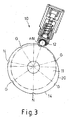
- FIG. 3 shows a sensor arrangement 10 similar to that shown in FIG. 1.
- the runway 14 has changeable, ramp-shaped diameter, the radial Change in diameter assigned to a specific angle of the shift drum can be.
- the individual rest points at gear positions G and N can also be assigned to singular diameters.
- the assignment to certain gear positions G, z. B. reverse, 1st, 2nd or 3rd gear and various intermediate neutral positions can be achieved.
- area 20, as already described in FIG. 2 does not become in practical operation drive through, so the position data there is not needed.
- the illustrated embodiments are only examples Realizations of the Invention.
- the invention is not based on the examples shown limited, more changes and training are possible.
- modifications of the sensor disk 11 are combined Acquisition of different position data in radial and axial directions is conceivable.
Landscapes
- Engineering & Computer Science (AREA)
- General Engineering & Computer Science (AREA)
- Mechanical Engineering (AREA)
- Gear-Shifting Mechanisms (AREA)
- Measurement Of Length, Angles, Or The Like Using Electric Or Magnetic Means (AREA)
- Control Of Transmission Device (AREA)
Priority Applications (3)
| Application Number | Priority Date | Filing Date | Title |
|---|---|---|---|
| EP02100293A EP1350991B1 (fr) | 2002-03-26 | 2002-03-26 | Dispositif capteur pour déterminer la position d'un tambour sélecteur de vitesses |
| DE50204390T DE50204390D1 (de) | 2002-03-26 | 2002-03-26 | Sensoranordnung zur Bestimmung der Schaltwalzenstellung |
| US10/249,186 US6730864B2 (en) | 2002-03-26 | 2003-03-20 | Sensor arrangement for determining selector drum position |
Applications Claiming Priority (1)
| Application Number | Priority Date | Filing Date | Title |
|---|---|---|---|
| EP02100293A EP1350991B1 (fr) | 2002-03-26 | 2002-03-26 | Dispositif capteur pour déterminer la position d'un tambour sélecteur de vitesses |
Publications (2)
| Publication Number | Publication Date |
|---|---|
| EP1350991A1 true EP1350991A1 (fr) | 2003-10-08 |
| EP1350991B1 EP1350991B1 (fr) | 2005-09-28 |
Family
ID=27838127
Family Applications (1)
| Application Number | Title | Priority Date | Filing Date |
|---|---|---|---|
| EP02100293A Expired - Lifetime EP1350991B1 (fr) | 2002-03-26 | 2002-03-26 | Dispositif capteur pour déterminer la position d'un tambour sélecteur de vitesses |
Country Status (3)
| Country | Link |
|---|---|
| US (1) | US6730864B2 (fr) |
| EP (1) | EP1350991B1 (fr) |
| DE (1) | DE50204390D1 (fr) |
Cited By (10)
| Publication number | Priority date | Publication date | Assignee | Title |
|---|---|---|---|---|
| WO2007012460A1 (fr) * | 2005-07-26 | 2007-02-01 | Knorr-Bremse Systeme für Nutzfahrzeuge GmbH | Dispositif d'actionnement pour une boite de vitesses |
| FR2904395A1 (fr) * | 2006-07-31 | 2008-02-01 | Peugeot Citroen Automobiles Sa | Procede de determination de l'etat de point mort d'une boite de vitesses de vehicule automobile |
| WO2008017520A1 (fr) | 2006-08-05 | 2008-02-14 | Schaeffler Kg | Disposition de capteur |
| WO2008107290A1 (fr) * | 2007-03-08 | 2008-09-12 | Schaeffler Kg | Barillet de sélection |
| WO2008122501A1 (fr) | 2007-04-07 | 2008-10-16 | Schaeffler Kg | Ensemble palpeur pour détecter la position de changement de vitesse d'une boîte de vitesses, et boîte de vitesses pourvue de l'ensemble palpeur |
| WO2009021795A1 (fr) * | 2007-08-10 | 2009-02-19 | Schaeffler Kg | Dispositif de détermination de la position de commutation d'un système mécanique |
| WO2010046218A1 (fr) * | 2008-10-24 | 2010-04-29 | Schaeffler Technologies Gmbh & Co. Kg | Unité de commutation à détecteur |
| WO2010069704A1 (fr) * | 2008-12-19 | 2010-06-24 | Schaeffler Technologies Gmbh & Co. Kg | Dispositif de détection de position d'un élément d'enclenchement mobile |
| EP2829772A1 (fr) * | 2013-07-26 | 2015-01-28 | AISIN AI Co., Ltd. | Dispositif de transmission de mouvement |
| DE102013205071B4 (de) | 2013-03-22 | 2019-08-01 | Schaeffler Technologies AG & Co. KG | Schaltvorrichtung für ein Zahnräderwechselgetriebe eines Kraftfahrzeugs und Linearwälzlager mit einer Schaltvorrichtung |
Families Citing this family (17)
| Publication number | Priority date | Publication date | Assignee | Title |
|---|---|---|---|---|
| US7199316B2 (en) * | 2004-09-10 | 2007-04-03 | W.T. Storey, Inc. | Multifunction switch for operating a device in a sealed container |
| DE102005034865B4 (de) * | 2005-07-26 | 2012-03-22 | Knorr-Bremse Systeme für Nutzfahrzeuge GmbH | Stellvorrichtung für ein Getriebe |
| JP4890185B2 (ja) * | 2006-09-29 | 2012-03-07 | 本田技研工業株式会社 | 車両用変速機 |
| JP4970099B2 (ja) * | 2007-03-22 | 2012-07-04 | 本田技研工業株式会社 | 車両用変速機 |
| US20080264329A1 (en) * | 2007-04-27 | 2008-10-30 | Denso Corporation | Dial device and method for manufacturing the same |
| DE102008053196A1 (de) | 2008-10-24 | 2010-04-29 | Schaeffler Kg | Sensorschalteinheit |
| DE102008053194A1 (de) | 2008-10-24 | 2010-04-29 | Schaeffler Kg | Schalteinheit |
| DE102009030823A1 (de) * | 2009-06-26 | 2011-01-20 | Koki Technik Transmission Systems Gmbh | Rastiervorrichtung für eine Schaltwelle |
| JP2013252778A (ja) * | 2012-06-06 | 2013-12-19 | Tokai Rika Co Ltd | 操作装置及びシフトレバー装置 |
| DE102013200658A1 (de) | 2013-01-17 | 2014-07-17 | Schaeffler Technologies Gmbh & Co. Kg | Schaltvorrichtung für ein Zahnräderwechselgetriebe eines Kraftfahrzeugs |
| DE202013004061U1 (de) | 2013-04-04 | 2013-06-14 | Schaeffler Technologies AG & Co. KG | Schaltelement eines Fahrzeuggangräderwechselgetriebes |
| KR101741441B1 (ko) * | 2014-07-24 | 2017-05-30 | 삼성중공업 주식회사 | 자동 도장장치 |
| DE102014019545A1 (de) | 2014-12-23 | 2016-06-23 | Daimler Ag | Schaltvorrichtung |
| CN107627096A (zh) * | 2017-10-10 | 2018-01-26 | 西安法士特汽车传动有限公司 | 一种在加工、装调及使用中手感可调的拨头机构 |
| JP7159973B2 (ja) * | 2019-05-22 | 2022-10-25 | トヨタ自動車株式会社 | 車両用レンジ切替装置 |
| DE102020126396B4 (de) | 2020-10-08 | 2023-10-26 | Schaeffler Technologies AG & Co. KG | Schaltelement und Schaltvorrichtung mit einem Schaltelement |
| JP2022158534A (ja) * | 2021-04-02 | 2022-10-17 | 株式会社東海理化電機製作所 | レバー操作装置 |
Citations (8)
| Publication number | Priority date | Publication date | Assignee | Title |
|---|---|---|---|---|
| GB2240372A (en) * | 1990-01-25 | 1991-07-31 | Automotive Products Plc | A gear position sensor |
| DE4314952A1 (de) | 1993-05-06 | 1994-11-10 | Fichtel & Sachs Ag | Vorrichtung zur Erfassung der Gangstellung eines Schaltgetriebes |
| DE19507621A1 (de) * | 1994-03-18 | 1995-09-21 | Volkswagen Ag | Schalthebelbetätigungssensor |
| EP0806591A1 (fr) * | 1996-05-07 | 1997-11-12 | MAGNETI MARELLI S.p.A. | Dispositif pour détecter la position d'un levier de commande pour sélectionner et changer une vitesse dans une boite de vitesses de véhicule |
| DE19920440A1 (de) | 1999-05-04 | 2000-11-16 | Getrag Getriebe Zahnrad | Stufengetriebe für ein Kraftfahrzeug |
| EP1063450A1 (fr) * | 1999-06-25 | 2000-12-27 | Hydraulik-Ring GmbH | Dispositif de mesure de deplacement et de commande pour boitier de vitesses |
| DE19929632A1 (de) | 1999-06-29 | 2001-01-18 | Bosch Gmbh Robert | Vorrichtung zur Positionserfassung von zwei Achsbewegungen |
| EP1094253A2 (fr) | 1999-10-18 | 2001-04-25 | BorgWarner Inc. | Moteur intégré pour commande de changement de vitesses et unité de commande électronique |
Family Cites Families (3)
| Publication number | Priority date | Publication date | Assignee | Title |
|---|---|---|---|---|
| US4296394A (en) * | 1978-02-13 | 1981-10-20 | Ragheb A Kadry | Magnetic switching device for contact-dependent and contactless switching |
| US5304981A (en) * | 1988-04-29 | 1994-04-19 | Chrysler Corporation | Method of determining the driver selected operating mode of an automatic transmission system |
| ATE259725T1 (de) * | 1997-03-20 | 2004-03-15 | Delphi Tech Inc | Lenkstockmodul mit zentraler elektrischer steuerungseinheit und nach radialem zusammenbau |
-
2002
- 2002-03-26 DE DE50204390T patent/DE50204390D1/de not_active Expired - Lifetime
- 2002-03-26 EP EP02100293A patent/EP1350991B1/fr not_active Expired - Lifetime
-
2003
- 2003-03-20 US US10/249,186 patent/US6730864B2/en not_active Expired - Lifetime
Patent Citations (8)
| Publication number | Priority date | Publication date | Assignee | Title |
|---|---|---|---|---|
| GB2240372A (en) * | 1990-01-25 | 1991-07-31 | Automotive Products Plc | A gear position sensor |
| DE4314952A1 (de) | 1993-05-06 | 1994-11-10 | Fichtel & Sachs Ag | Vorrichtung zur Erfassung der Gangstellung eines Schaltgetriebes |
| DE19507621A1 (de) * | 1994-03-18 | 1995-09-21 | Volkswagen Ag | Schalthebelbetätigungssensor |
| EP0806591A1 (fr) * | 1996-05-07 | 1997-11-12 | MAGNETI MARELLI S.p.A. | Dispositif pour détecter la position d'un levier de commande pour sélectionner et changer une vitesse dans une boite de vitesses de véhicule |
| DE19920440A1 (de) | 1999-05-04 | 2000-11-16 | Getrag Getriebe Zahnrad | Stufengetriebe für ein Kraftfahrzeug |
| EP1063450A1 (fr) * | 1999-06-25 | 2000-12-27 | Hydraulik-Ring GmbH | Dispositif de mesure de deplacement et de commande pour boitier de vitesses |
| DE19929632A1 (de) | 1999-06-29 | 2001-01-18 | Bosch Gmbh Robert | Vorrichtung zur Positionserfassung von zwei Achsbewegungen |
| EP1094253A2 (fr) | 1999-10-18 | 2001-04-25 | BorgWarner Inc. | Moteur intégré pour commande de changement de vitesses et unité de commande électronique |
Cited By (16)
| Publication number | Priority date | Publication date | Assignee | Title |
|---|---|---|---|---|
| DE102005034864B4 (de) * | 2005-07-26 | 2008-11-27 | Knorr-Bremse Systeme für Nutzfahrzeuge GmbH | Stellvorrichtung für ein Getriebe |
| DE102005034864A1 (de) * | 2005-07-26 | 2007-02-01 | Knorr-Bremse Systeme für Nutzfahrzeuge GmbH | Stellvorrichtung für ein Getriebe |
| WO2007012460A1 (fr) * | 2005-07-26 | 2007-02-01 | Knorr-Bremse Systeme für Nutzfahrzeuge GmbH | Dispositif d'actionnement pour une boite de vitesses |
| CN101258341B (zh) * | 2005-07-26 | 2012-06-27 | 克诺尔商用车制动系统有限公司 | 变速器的调节装置 |
| US7543515B2 (en) | 2005-07-26 | 2009-06-09 | Knorr-Bremse Systeme Fuer Nutzfahrzeuge Gmbh | Adjusting device for a transmission |
| FR2904395A1 (fr) * | 2006-07-31 | 2008-02-01 | Peugeot Citroen Automobiles Sa | Procede de determination de l'etat de point mort d'une boite de vitesses de vehicule automobile |
| WO2008015351A1 (fr) * | 2006-07-31 | 2008-02-07 | Peugeot Citroën Automobiles SA | Procede de determination de l'etat de point mort d'une boite de vitesses de vehicule automobile |
| WO2008017520A1 (fr) | 2006-08-05 | 2008-02-14 | Schaeffler Kg | Disposition de capteur |
| WO2008107290A1 (fr) * | 2007-03-08 | 2008-09-12 | Schaeffler Kg | Barillet de sélection |
| WO2008122501A1 (fr) | 2007-04-07 | 2008-10-16 | Schaeffler Kg | Ensemble palpeur pour détecter la position de changement de vitesse d'une boîte de vitesses, et boîte de vitesses pourvue de l'ensemble palpeur |
| CN101652584B (zh) * | 2007-04-07 | 2015-09-23 | 舍弗勒技术股份两合公司 | 检测变速器的档位的探测器装置和具有探测器装置的变速器 |
| WO2009021795A1 (fr) * | 2007-08-10 | 2009-02-19 | Schaeffler Kg | Dispositif de détermination de la position de commutation d'un système mécanique |
| WO2010046218A1 (fr) * | 2008-10-24 | 2010-04-29 | Schaeffler Technologies Gmbh & Co. Kg | Unité de commutation à détecteur |
| WO2010069704A1 (fr) * | 2008-12-19 | 2010-06-24 | Schaeffler Technologies Gmbh & Co. Kg | Dispositif de détection de position d'un élément d'enclenchement mobile |
| DE102013205071B4 (de) | 2013-03-22 | 2019-08-01 | Schaeffler Technologies AG & Co. KG | Schaltvorrichtung für ein Zahnräderwechselgetriebe eines Kraftfahrzeugs und Linearwälzlager mit einer Schaltvorrichtung |
| EP2829772A1 (fr) * | 2013-07-26 | 2015-01-28 | AISIN AI Co., Ltd. | Dispositif de transmission de mouvement |
Also Published As
| Publication number | Publication date |
|---|---|
| US20030184428A1 (en) | 2003-10-02 |
| DE50204390D1 (de) | 2006-02-09 |
| EP1350991B1 (fr) | 2005-09-28 |
| US6730864B2 (en) | 2004-05-04 |
Similar Documents
| Publication | Publication Date | Title |
|---|---|---|
| EP1350991B1 (fr) | Dispositif capteur pour déterminer la position d'un tambour sélecteur de vitesses | |
| EP0794362B1 (fr) | Mécanisme de sélection de rapport pour une transmission | |
| DE102009058023A1 (de) | Schalteinheit eines Kraftfahrzeugschaltgetriebes | |
| DE10203633A1 (de) | Schaltvorrichtung eines Getriebes | |
| WO2010069705A1 (fr) | Palier à roulement composé de deux composants pouvant être déplacés l'un par rapport à l'autre au moins axialement, conçu en particulier pour des éléments de changement de vitesse | |
| EP2217837B1 (fr) | Unité de commutation et procédé de fabrication de cette unité | |
| WO2010057758A1 (fr) | Dispositif pour détecter des états de changement de vitesses d'un organe mobile de changement de vitesses et d'ajustement | |
| WO2009118131A1 (fr) | Agencement de support d'une tige de commande avec capteur de détermination de la position | |
| DE10153915B4 (de) | Verfahren und Vorrichtung zur Fassung der Ist-Stellung eines zu lenkenden Rades bei einem Flurförderzeug mit einer elektrischen Lenkung | |
| EP3019878A2 (fr) | Dispositif de mesure de la vitesse de rotation d'un mécanisme et procédé de mesure de vitesse de rotation | |
| EP2379915B1 (fr) | Dispositif de détection de position d'un élément d'enclenchement mobile | |
| DE102008058163A1 (de) | Vorrichtung zur Erfassung sämtlicher Schaltpositionen eines Schaltgetriebes | |
| DE102013214358B4 (de) | Messvorrichtung für ein manuelles Schaltgetriebe | |
| WO2003081088A1 (fr) | Dispositif de selection pour commander la selection de rapports d'une boite de vitesses d'automobile | |
| DE102010011833A1 (de) | Schaltvorrichtung eines Kraftfahrzeugwechselgetriebes | |
| DE10225467A1 (de) | Vorrichtung zur Durchführung von Schaltvorgängen von Getrieben eines Kraftfahrzeuges | |
| EP1196701B1 (fr) | Dispositif de detection de la position de deux mouvements axiaux | |
| DE102013200658A1 (de) | Schaltvorrichtung für ein Zahnräderwechselgetriebe eines Kraftfahrzeugs | |
| EP2235601A1 (fr) | Unité de commutation et son procédé de fabrication | |
| DE69717725T2 (de) | Aufnehmer zur Erzeugung eines Signals, das eine Gangwahl und/oder einen eingelegten Getriebegang anzeigt | |
| DE10352962A1 (de) | Gangschaltmechanismus | |
| DE19507621B4 (de) | Schalthebelbetätigungssensor | |
| DE102018214082A1 (de) | Klaue mit Geberkontur und Kupplungsanordnung | |
| DE10111994B4 (de) | Anordnung zum Messen einer Winkelposition einer Schaltwalze eines Getriebes, insbesondere für ein Kraftfahrzeuggetriebe | |
| WO2022073537A1 (fr) | Élément et dispositif de commutation à élément de commutation |
Legal Events
| Date | Code | Title | Description |
|---|---|---|---|
| PUAI | Public reference made under article 153(3) epc to a published international application that has entered the european phase |
Free format text: ORIGINAL CODE: 0009012 |
|
| AK | Designated contracting states |
Kind code of ref document: A1 Designated state(s): AT BE CH CY DE DK ES FI FR GB GR IE IT LI LU MC NL PT SE TR |
|
| AX | Request for extension of the european patent |
Extension state: AL LT LV MK RO SI |
|
| 17P | Request for examination filed |
Effective date: 20040408 |
|
| AKX | Designation fees paid |
Designated state(s): DE FR GB |
|
| 17Q | First examination report despatched |
Effective date: 20040615 |
|
| GRAP | Despatch of communication of intention to grant a patent |
Free format text: ORIGINAL CODE: EPIDOSNIGR1 |
|
| GRAS | Grant fee paid |
Free format text: ORIGINAL CODE: EPIDOSNIGR3 |
|
| GRAA | (expected) grant |
Free format text: ORIGINAL CODE: 0009210 |
|
| AK | Designated contracting states |
Kind code of ref document: B1 Designated state(s): DE FR GB |
|
| REG | Reference to a national code |
Ref country code: GB Ref legal event code: FG4D Free format text: NOT ENGLISH |
|
| GBT | Gb: translation of ep patent filed (gb section 77(6)(a)/1977) |
Effective date: 20060104 |
|
| REF | Corresponds to: |
Ref document number: 50204390 Country of ref document: DE Date of ref document: 20060209 Kind code of ref document: P |
|
| ET | Fr: translation filed | ||
| PLBE | No opposition filed within time limit |
Free format text: ORIGINAL CODE: 0009261 |
|
| STAA | Information on the status of an ep patent application or granted ep patent |
Free format text: STATUS: NO OPPOSITION FILED WITHIN TIME LIMIT |
|
| 26N | No opposition filed |
Effective date: 20060629 |
|
| REG | Reference to a national code |
Ref country code: FR Ref legal event code: PLFP Year of fee payment: 15 |
|
| REG | Reference to a national code |
Ref country code: FR Ref legal event code: PLFP Year of fee payment: 16 |
|
| REG | Reference to a national code |
Ref country code: FR Ref legal event code: PLFP Year of fee payment: 17 |
|
| PGFP | Annual fee paid to national office [announced via postgrant information from national office to epo] |
Ref country code: FR Payment date: 20210218 Year of fee payment: 20 |
|
| PGFP | Annual fee paid to national office [announced via postgrant information from national office to epo] |
Ref country code: GB Payment date: 20210311 Year of fee payment: 20 Ref country code: DE Payment date: 20210210 Year of fee payment: 20 |
|
| REG | Reference to a national code |
Ref country code: DE Ref legal event code: R071 Ref document number: 50204390 Country of ref document: DE |
|
| REG | Reference to a national code |
Ref country code: GB Ref legal event code: PE20 Expiry date: 20220325 |
|
| PG25 | Lapsed in a contracting state [announced via postgrant information from national office to epo] |
Ref country code: GB Free format text: LAPSE BECAUSE OF EXPIRATION OF PROTECTION Effective date: 20220325 |