EP1350971A2 - Lageranordnung - Google Patents
Lageranordnung Download PDFInfo
- Publication number
- EP1350971A2 EP1350971A2 EP02023924A EP02023924A EP1350971A2 EP 1350971 A2 EP1350971 A2 EP 1350971A2 EP 02023924 A EP02023924 A EP 02023924A EP 02023924 A EP02023924 A EP 02023924A EP 1350971 A2 EP1350971 A2 EP 1350971A2
- Authority
- EP
- European Patent Office
- Prior art keywords
- ball joint
- bearing arrangement
- bearing
- spring body
- arrangement according
- Prior art date
- Legal status (The legal status is an assumption and is not a legal conclusion. Google has not performed a legal analysis and makes no representation as to the accuracy of the status listed.)
- Withdrawn
Links
- 239000013536 elastomeric material Substances 0.000 claims description 4
- 239000000314 lubricant Substances 0.000 claims description 4
- 238000005096 rolling process Methods 0.000 claims description 4
- 230000001050 lubricating effect Effects 0.000 claims description 3
- 238000007789 sealing Methods 0.000 claims description 3
- 229920001971 elastomer Polymers 0.000 abstract 1
- 239000000806 elastomer Substances 0.000 abstract 1
- 239000000463 material Substances 0.000 abstract 1
- 230000006378 damage Effects 0.000 description 2
- 230000002950 deficient Effects 0.000 description 2
- 238000004519 manufacturing process Methods 0.000 description 2
- 241000209035 Ilex Species 0.000 description 1
- 238000004026 adhesive bonding Methods 0.000 description 1
- 238000010276 construction Methods 0.000 description 1
- 239000004519 grease Substances 0.000 description 1
- 238000003860 storage Methods 0.000 description 1
Images



Classifications
-
- F—MECHANICAL ENGINEERING; LIGHTING; HEATING; WEAPONS; BLASTING
- F16—ENGINEERING ELEMENTS AND UNITS; GENERAL MEASURES FOR PRODUCING AND MAINTAINING EFFECTIVE FUNCTIONING OF MACHINES OR INSTALLATIONS; THERMAL INSULATION IN GENERAL
- F16C—SHAFTS; FLEXIBLE SHAFTS; ELEMENTS OR CRANKSHAFT MECHANISMS; ROTARY BODIES OTHER THAN GEARING ELEMENTS; BEARINGS
- F16C27/00—Elastic or yielding bearings or bearing supports, for exclusively rotary movement
- F16C27/06—Elastic or yielding bearings or bearing supports, for exclusively rotary movement by means of parts of rubber or like materials
- F16C27/066—Ball or roller bearings
-
- F—MECHANICAL ENGINEERING; LIGHTING; HEATING; WEAPONS; BLASTING
- F16—ENGINEERING ELEMENTS AND UNITS; GENERAL MEASURES FOR PRODUCING AND MAINTAINING EFFECTIVE FUNCTIONING OF MACHINES OR INSTALLATIONS; THERMAL INSULATION IN GENERAL
- F16C—SHAFTS; FLEXIBLE SHAFTS; ELEMENTS OR CRANKSHAFT MECHANISMS; ROTARY BODIES OTHER THAN GEARING ELEMENTS; BEARINGS
- F16C23/00—Bearings for exclusively rotary movement adjustable for aligning or positioning
- F16C23/06—Ball or roller bearings
- F16C23/08—Ball or roller bearings self-adjusting
- F16C23/082—Ball or roller bearings self-adjusting by means of at least one substantially spherical surface
- F16C23/084—Ball or roller bearings self-adjusting by means of at least one substantially spherical surface sliding on a complementary spherical surface
-
- F—MECHANICAL ENGINEERING; LIGHTING; HEATING; WEAPONS; BLASTING
- F16—ENGINEERING ELEMENTS AND UNITS; GENERAL MEASURES FOR PRODUCING AND MAINTAINING EFFECTIVE FUNCTIONING OF MACHINES OR INSTALLATIONS; THERMAL INSULATION IN GENERAL
- F16C—SHAFTS; FLEXIBLE SHAFTS; ELEMENTS OR CRANKSHAFT MECHANISMS; ROTARY BODIES OTHER THAN GEARING ELEMENTS; BEARINGS
- F16C19/00—Bearings with rolling contact, for exclusively rotary movement
- F16C19/02—Bearings with rolling contact, for exclusively rotary movement with bearing balls essentially of the same size in one or more circular rows
- F16C19/04—Bearings with rolling contact, for exclusively rotary movement with bearing balls essentially of the same size in one or more circular rows for radial load mainly
- F16C19/06—Bearings with rolling contact, for exclusively rotary movement with bearing balls essentially of the same size in one or more circular rows for radial load mainly with a single row or balls
Definitions
- Bearing arrangements are generally known and come to, for example Storage of shafts for use.
- Known bearing arrangements include e.g. a bearing designed as a roller or plain bearing, which means a spring body made of elastomeric material directly with a Bearing radially outer circumferential enclosing housing is connected.
- Such bearing arrangements are only satisfactory Properties of use for a sufficiently long period of use when it is ensured that the connection surfaces of the spring body on the machine elements bordering radially inside and outside are not relative are gimbally deflected towards each other.
- the wave to be supported, the Bearings and the housing must therefore be used during the intended use Use of the bearing arrangement always arranged axially parallel to each other his.
- the spring body As soon as the shaft is gimbally deflected in relation to the spring body, the spring body, viewed along its circumference, is of different sizes Exposed to tensile and compressive stresses, with regard to constant good performance characteristics during a long service life of Disadvantage is. The spring body is damaged and / or destroyed.
- the invention has for its object a bearing arrangement of the beginning to develop the type mentioned in such a way that it remains consistently good Features of use during a long period of use even then has when the shaft, based on the spring body, is gimbally deflected becomes. In such an operating state, undesirable voltages should occur be avoided within the spring body.
- a bearing arrangement comprising a Ball joint with an annular spherical body and a congruent one designed, pan-shaped guide ring for receiving the spherical body, the ball joint in the radial direction on the one hand with an elastic compliant, ring-shaped spring body made of elastomeric material is connected and in the radial direction on the other hand with a bearing, the Spring body on the side radially facing away from the ball joint with a Housing is connected, the bearing gimbal relative to the housing is deflectable and the facing surfaces of the ball joint and housing during the intended use of the Bearing arrangement always without relative cardanic deflection to each other are arranged.
- the spring body is always free from gimbal loads, even if it is too Bearing shaft and thus the bearing surrounding the shaft, based on the housing, gimbaled. Unwanted high local Tensile stresses within the spring body that lead to a Damage / destruction can become reliable avoided.
- the radially opposite connection surfaces of the Spring body are during the intended use of the Bearing arrangement always without relative cardanic deflection to each other arranged.
- the bearing arrangement described above is particularly advantageous then when the spring body, in longitudinal section of the bearing arrangement considered, is formed as a fold with a substantially C-shaped shape. Such folds are particularly sensitive to tensile stresses.
- the Spring body is radially and / or axially resilient and can be used as a bearing, depending on the respective application, a rolling or plain bearing Application.
- the spring body with the facing surfaces of ball joint and Housing is connected directly.
- the advantage here is that the Bearing arrangement has a simple and low-parts structure and therefore is inexpensive to manufacture.
- the spring body can be adhesively connected to the surfaces.
- the cohesive Connection can, for example, by gluing or by The components are vulcanized.
- the spring body can at least on the be connected to the ball joint side with a sleeve that the Ball joint encloses directly.
- the sleeve and radial Adjacent components of the ball joint can be non-positive, for example by shrink-fitting.
- the spring body facing each other Surfaces of the ball joint and housing are in direct contact
- the spring body with the sleeve is independent of the ball joint or the unit comprising the ball joint and the bearing is interchangeable. If, for example, the spring body or the ball joint is defective, it can defective component replaced regardless of the ball joint or the spring body become. With a view to minimizing operating costs during the use of the bearing arrangement is of particular advantage.
- the spherical body can form part of the bearing.
- the comparatively more complicated bearings have the advantage of a low-parts Construction of the entire bearing arrangement opposite. As a warehouse can Rolling bearings or a plain bearing are used.
- the guide ring can, viewed in the longitudinal section of the sealing arrangement, be formed in two parts and comprise two half-shells, the half-shells are assigned adjacent to each other with an axial distance.
- the through the gap formed can be used as a lubricant groove for lubricating the Contact surfaces of the spherical body and guide ring can be formed.
- the Lubricant groove can be filled with a grease, for example.
- the half-shells can be axially centered in relation to the bearing arrangement intersecting, imaginary radial plane, mirror-symmetrical his. Due to the half shells, which are designed as identical parts, the Bearing arrangement easy and inexpensive to manufacture. By the same design Half shells assembly errors are reduced to a minimum.
- the bearing arrangement described above is preferably used as a cardan shaft bearing used in motor vehicles.
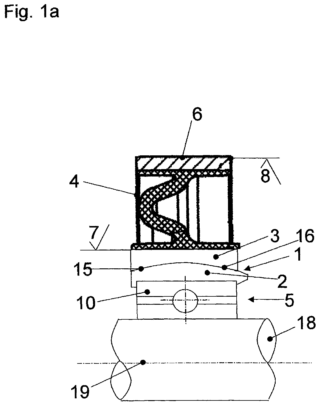
- FIGs 1 to 3 a bearing arrangement is shown, which for Bearing of a propeller shaft 18 of a motor vehicle is used.
- the cardan shaft 18 extends axially parallel to the axis of symmetry 19, in Figures 1 b to 3 b, the propeller shaft 18 is in contrast each gimbally deflected.
- the spherical body 2 is, as here in Longitudinal section shown, substantially hemispherical on the outer circumference educated.
- the ball joint 1 is with the outer circumference of the housing 6 radial distance enclosed, being in the formed by the distance Gap of the spring body 4 is arranged.
- the spring body 4 consists of a elastomeric material and, viewed in longitudinal section, is essentially Wrinkle-shaped, the fold is essentially C-shaped and is open in the axial direction.
- the spring body 4 shown here is both in resilient in the radial as well as in the axial direction, so that for example Thermal expansion of the propeller shaft 18 in the axial direction of the bearing arrangement or unbalance of the bearing assembly in the radial direction from Spring body 4 are added.
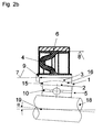
- the arrangement of the ball joint within the bearing arrangement is from crucial importance. As shown in Figures 1 b to 3 b, has the position of the guide ring 3 and the spring body 4 relative to the housing 6 not changed, although the cardan shaft 18, based on the representations in 1 a to 3 a, is gimbally deflected.
- the facing each other Surfaces 7, 8 of ball joint 1 and housing 6 are both in the Representations 1 a to 3 a as well as in representations 1 b to 3 b always arranged parallel to each other; the mutually facing surfaces 7, 8 of ball joint 1 and housing 6 are during the intended use Always use the bearing arrangement without relative gimbal deflection arranged to each other, as well as the connection surfaces of the spring body 4 on the radially adjacent components.
- Through the ball joint 1 and its The cardanic deflection of the crankshaft 18 has no influence on the arrangement to the stresses within the spring body 4.
- the ball joint 1 is, as in the exemplary embodiment according to Figure 2 also formed in two parts and consists of the spherical body 2 and the guide ring 3.
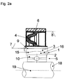
- the exemplary embodiment from FIG. 2 differs from the exemplary embodiment from Figure 1 in that the spring body 4 radially on the inside with a sleeve 9 is connected, the sleeve 9, the ball joint 1 radially encloses on the outside and is connected to it in a rotationally fixed manner.
- the sleeve 9 is preferably detachably connected non-destructively to the ball joint 1.
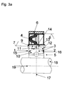
- the embodiment of Figure 3 differs from that previously Exemplary embodiments described in that the guide ring 3, in Longitudinal section of the sealing arrangement considered, is formed in two parts and comprises two half-shells 11, 12, the half-shells 11, 12 with each other axial distance are assigned adjacent. The one by the distance The gap 13 formed is a lubricant groove 14 for lubricating the contact surfaces 15, 16 formed by spherical body 2 and guide ring 3. Moreover are the half-shells 11, 12, based on the imaginary radial plane 17, mirror-symmetrical.
- the radially facing the spring body 4 Surface of the bearing 5 has the shape of the spherical body 2 and is in the Congruently designed recess of the guide ring 3 is arranged.
Landscapes
- Engineering & Computer Science (AREA)
- General Engineering & Computer Science (AREA)
- Mechanical Engineering (AREA)
- Pivots And Pivotal Connections (AREA)
- Support Of The Bearing (AREA)
Abstract
Description
- Figur 1 a und 1 b
- ein erstes Ausführungsbeispiel, bei dem der Federkörper, in radialer Richtung betrachtet, die einander zugewandten Oberflächen von Kugelgelenk und Gehäuse unmittelbar anliegend berührt und mit diesen verbunden ist,
- Figur 2 a und 2 b
- ein zweites Ausführungsbeispiel, das sich vom ersten Ausführungsbeispiel aus Figur 1 durch eine Hülse unterscheidet, die in radialer Richtung zwischen dem Führungsring des Kugelgelenks und dem Federkörper angeordnet ist,
- Figur 3 a und 3 b
- ein drittes Ausführungsbeispiel, ähnlich dem zweiten Ausführungsbeispiel aus Figur 2, wobei der Kugelkörper durch den Außenring eines Wälzlagers gebildet ist.
Claims (9)
- Lageranordnung, umfassend ein Kugelgelenk (1) mit einem ringförmigen Kugelkörper (2) und einem kongruent gestalteten, pfannenförmigen Führungsring (3) zur Aufnahme des Kugelkörpers (2), wobei das Kugelgelenk (1) in radialer Richtung einerseits mit einem elastisch nachgiebigen, ringförmigen Federkörper (4) aus elastomerem Werkstoff verbunden ist und in radialer Richtung andererseits mit Lager (5), wobei der Federkörper (4) auf der dem Kugelgelenk (1) radial abgewandten Seite mit einem Gehäuse (6) verbunden ist, wobei das Lager (5) relativ zum Gehäuse (6) kardanisch auslenkbar ist und wobei die einander zugewandten Oberflächen (7, 8) von Kugelgelenk (1) und Gehäuse (6) während der bestimmungsgemäßen Verwendung der Lageranordnung stets ohne relative kardanische Auslenkung zueinander angeordnet sind.
- Lageranordnung nach Anspruch 1, dadurch gekennzeichnet, dass der Federkörper (4) mit den einander zugewandten Oberflächen (7, 8) von Kugelgelenk (1) und Gehäuse (6) unmittelbar anliegend verbunden ist.
- Lageranordnung nach Anspruch 2, dadurch gekennzeichnet, dass der Federkörper (4) mit den Oberflächen (7, 8) adhäsiv verbunden ist.
- Lageranordnung nach einem der Ansprüche 1 bis 3, dadurch gekennzeichnet, dass der Federkörper (4) zumindest auf der dem Kugelgelenk (1) zugewandten Seite mit einer Hülse (9) verbunden ist, die das Kugelgelenk (1) unmittelbar anliegend umschließt.
- Lageranordnung nach einem der Ansprüche 1 bis 4, dadurch gekennzeichnet, dass der Kugelkörper (2) einen Bestandteil des Lagers (5) bildet.
- Lageranordnung nach Anspruch 5, dadurch gekennzeichnet, dass der Kugelkörper (2) durch den Außenring (10) eines Wälzlagers gebildet ist.
- Lageranordnung nach einem der Ansprüche 1 bis 6, dadurch gekennzeichnet, dass der Führungsring (3), im Längsschnitt der Dichtungsanordnung betrachtet, zweiteilig ausgebildet ist und zwei Halbschalen (11, 12) umfasst und dass die Halbschalen (11, 12) einander mit axialem Abstand benachbart zugeordnet sind.
- Lageranordnung nach Anspruch 7, dadurch gekennzeichnet, dass der durch den Abstand gebildete Spalt (13) als Schmiermittelnut (14) zur Schmierung der Kontaktflächen (15, 16) von Kugelkörper (2) und Führungsring (3) ausgebildet ist.
- Lageranordnung nach einem der Ansprüche 7 oder 8, dadurch gekennzeichnet, dass die Halbschalen (11, 12), bezogen auf eine die Lageranordnung axial mittig durchschneidende, gedachte Radialebene (17), spiegelsymmetrisch ausgebildet sind.
Applications Claiming Priority (2)
| Application Number | Priority Date | Filing Date | Title |
|---|---|---|---|
| DE10215221A DE10215221B4 (de) | 2002-04-06 | 2002-04-06 | Lageranordnung |
| DE10215221 | 2002-04-06 |
Publications (2)
| Publication Number | Publication Date |
|---|---|
| EP1350971A2 true EP1350971A2 (de) | 2003-10-08 |
| EP1350971A3 EP1350971A3 (de) | 2005-03-16 |
Family
ID=27816178
Family Applications (1)
| Application Number | Title | Priority Date | Filing Date |
|---|---|---|---|
| EP02023924A Withdrawn EP1350971A3 (de) | 2002-04-06 | 2002-10-25 | Lageranordnung |
Country Status (3)
| Country | Link |
|---|---|
| US (1) | US6948857B2 (de) |
| EP (1) | EP1350971A3 (de) |
| DE (1) | DE10215221B4 (de) |
Cited By (4)
| Publication number | Priority date | Publication date | Assignee | Title |
|---|---|---|---|---|
| EP1834105A4 (de) * | 2004-12-31 | 2008-11-05 | Dana Corp | Mittellageranordnung zum rotierenden tragen einer welle bei zu einer trägeroberfläche relativ variierenden winkeln |
| WO2013068104A1 (de) * | 2011-11-07 | 2013-05-16 | Thyssenkrupp Presta Ag | Kugelgewindetrieb mit lagerausgleich |
| US9677605B2 (en) | 2015-05-29 | 2017-06-13 | Bearing Technologies, Ltd. | Hanger bearing assembly |
| EP3516260A1 (de) * | 2016-09-26 | 2019-07-31 | Vibracoustic GmbH | Wellenlager |
Families Citing this family (11)
| Publication number | Priority date | Publication date | Assignee | Title |
|---|---|---|---|---|
| US7901142B2 (en) * | 2007-03-20 | 2011-03-08 | Goodrich Corporation | Diaphragm bearing hanger assembly |
| DE102009017192B4 (de) * | 2009-04-09 | 2011-04-28 | Aktiebolaget Skf | Lageranordnung für eine Tragrolle |
| JP6008090B2 (ja) * | 2012-04-26 | 2016-10-19 | Nok株式会社 | センターベアリングサポート |
| DE102013210218A1 (de) * | 2013-06-03 | 2014-12-04 | Schaeffler Technologies Gmbh & Co. Kg | Lageranordnung mit einem Fanglager |
| TWI580523B (zh) * | 2014-01-21 | 2017-05-01 | 中國砂輪企業股份有限公司 | 具有最佳磨料露出率之化學機械研磨修整器 |
| CN105471160A (zh) * | 2014-07-31 | 2016-04-06 | 德昌电机(深圳)有限公司 | 滚动轴承紧固结构 |
| DE102016012246A1 (de) * | 2016-10-14 | 2018-04-19 | Thyssenkrupp Ag | Elektromechanische Servolenkung mit gefederter Lageranordnung |
| DE102017110874A1 (de) * | 2017-05-18 | 2018-11-22 | Henniges Automotive Gmbh & Co. Kg | Lageranordnung |
| DE102017113999B4 (de) * | 2017-06-23 | 2022-04-28 | Vibracoustic Se | Wellenlager |
| RU2766647C1 (ru) * | 2018-09-21 | 2022-03-15 | Тирсан Кардан Сан. Ве Тидж. А.С. | Подшипниковый узел карданного вала, карданный вал и способ изготовления такого вала |
| US11359672B2 (en) * | 2019-12-10 | 2022-06-14 | Koch Engineered Solutions, Llc | Bearing assembly for rotary electric machine |
Family Cites Families (5)
| Publication number | Priority date | Publication date | Assignee | Title |
|---|---|---|---|---|
| GB1051448A (de) * | 1900-01-01 | |||
| DE3337932A1 (de) * | 1983-10-17 | 1985-05-02 | Schweizerische Aluminium Ag, Chippis | Lagervorrichtung fuer radachsen |
| DE3933163A1 (de) * | 1988-10-27 | 1990-05-03 | Toyoda Gosei Kk | Zylindrische daempfungsbuchse |
| DE4040444C1 (en) * | 1990-12-18 | 1992-04-16 | Fa. Carl Freudenberg, 6940 Weinheim, De | Cardan shaft bearing with two mutually surrounding supports - has axial fold at peripheral point(s) interrupted by cross-fold(s), as bellows deformation section |
| DE19748726A1 (de) * | 1997-11-05 | 1999-05-20 | Freudenberg Carl Fa | Lageranordnung |
-
2002
- 2002-04-06 DE DE10215221A patent/DE10215221B4/de not_active Expired - Fee Related
- 2002-10-25 EP EP02023924A patent/EP1350971A3/de not_active Withdrawn
-
2003
- 2003-03-31 US US10/403,654 patent/US6948857B2/en not_active Expired - Fee Related
Non-Patent Citations (1)
| Title |
|---|
| None |
Cited By (6)
| Publication number | Priority date | Publication date | Assignee | Title |
|---|---|---|---|---|
| EP1834105A4 (de) * | 2004-12-31 | 2008-11-05 | Dana Corp | Mittellageranordnung zum rotierenden tragen einer welle bei zu einer trägeroberfläche relativ variierenden winkeln |
| WO2013068104A1 (de) * | 2011-11-07 | 2013-05-16 | Thyssenkrupp Presta Ag | Kugelgewindetrieb mit lagerausgleich |
| US9376139B2 (en) | 2011-11-07 | 2016-06-28 | Thyssenkrupp Presta Ag | Ball screw having bearing compensation |
| US9677605B2 (en) | 2015-05-29 | 2017-06-13 | Bearing Technologies, Ltd. | Hanger bearing assembly |
| EP3516260A1 (de) * | 2016-09-26 | 2019-07-31 | Vibracoustic GmbH | Wellenlager |
| US10876574B2 (en) | 2016-09-26 | 2020-12-29 | Vibracoustic Gmbh | Shaft bearing |
Also Published As
| Publication number | Publication date |
|---|---|
| DE10215221A1 (de) | 2003-10-23 |
| US6948857B2 (en) | 2005-09-27 |
| EP1350971A3 (de) | 2005-03-16 |
| US20030219183A1 (en) | 2003-11-27 |
| DE10215221B4 (de) | 2004-04-22 |
Similar Documents
| Publication | Publication Date | Title |
|---|---|---|
| DE10215221B4 (de) | Lageranordnung | |
| DE4412132C5 (de) | Abdichtung für eine Gelenkkreuzbüchse | |
| DE69929554T2 (de) | Lagervorrichtung mit sphärischen Lagerflächen | |
| DE2707890C3 (de) | Koppelring-Kardangelenk | |
| EP0286883B1 (de) | Lagerung eines Abgasturboladers | |
| DE2511021A1 (de) | Selbstdimensionierende lageranordnung | |
| EP3045763A1 (de) | Gummi-metall-hülsenlager | |
| DE102010052101A1 (de) | Lagervorrichtung mit einem Fanglager | |
| DE69423386T2 (de) | Schwingungsdämpfer für eine Membrankupplung | |
| DE10134106A1 (de) | Kugelzapfgelenk | |
| DE19925895A1 (de) | Kreuzgelenk für eine Kardangelenkanordnung | |
| DE2917012A1 (de) | Schutzvorrichtung fuer eine gelenkverbindung | |
| DE3536283C2 (de) | ||
| DE3346666A1 (de) | Elastisches dreh-gleitlager | |
| EP0035283A1 (de) | Wellenkupplung | |
| DE3202381A1 (de) | "radial - wellendichtring" | |
| DE10048998C1 (de) | Elastische Lageraufhängung für ein Wellenlager | |
| DE4331108C1 (de) | Gleichlaufdrehgelenk | |
| DE1961962A1 (de) | Kardan- bzw. Kreuzgelenk | |
| DE4228170A1 (de) | Lager | |
| DE2916186A1 (de) | Elastisches kugelgelenklager | |
| EP1201950B1 (de) | Achsmanschette | |
| DE102018215839A1 (de) | Gaslageraufhängung zur axialen Lagerung einer Welle | |
| DE102004044776B4 (de) | Zapfengelenk | |
| DE10258985B4 (de) | Kugelgelenk |
Legal Events
| Date | Code | Title | Description |
|---|---|---|---|
| PUAI | Public reference made under article 153(3) epc to a published international application that has entered the european phase |
Free format text: ORIGINAL CODE: 0009012 |
|
| AK | Designated contracting states |
Kind code of ref document: A2 Designated state(s): AT BE BG CH CY CZ DE DK EE ES FI FR GB GR IE IT LI LU MC NL PT SE SK TR |
|
| AX | Request for extension of the european patent |
Extension state: AL LT LV MK RO SI |
|
| PUAL | Search report despatched |
Free format text: ORIGINAL CODE: 0009013 |
|
| AK | Designated contracting states |
Kind code of ref document: A3 Designated state(s): AT BE BG CH CY CZ DE DK EE ES FI FR GB GR IE IT LI LU MC NL PT SE SK TR |
|
| AX | Request for extension of the european patent |
Extension state: AL LT LV MK RO SI |
|
| RIC1 | Information provided on ipc code assigned before grant |
Ipc: 7F 16C 27/06 B Ipc: 7F 16C 23/08 B Ipc: 7F 16C 23/04 A |
|
| 17P | Request for examination filed |
Effective date: 20050210 |
|
| AKX | Designation fees paid |
Designated state(s): DE FR GB IT SE |
|
| 17Q | First examination report despatched |
Effective date: 20060823 |
|
| GRAP | Despatch of communication of intention to grant a patent |
Free format text: ORIGINAL CODE: EPIDOSNIGR1 |
|
| STAA | Information on the status of an ep patent application or granted ep patent |
Free format text: STATUS: THE APPLICATION IS DEEMED TO BE WITHDRAWN |
|
| 18D | Application deemed to be withdrawn |
Effective date: 20080326 |