EP1350734A2 - Verbinden einer Kunststoffarmatur auf einem Glasbehälter - Google Patents
Verbinden einer Kunststoffarmatur auf einem Glasbehälter Download PDFInfo
- Publication number
- EP1350734A2 EP1350734A2 EP03003516A EP03003516A EP1350734A2 EP 1350734 A2 EP1350734 A2 EP 1350734A2 EP 03003516 A EP03003516 A EP 03003516A EP 03003516 A EP03003516 A EP 03003516A EP 1350734 A2 EP1350734 A2 EP 1350734A2
- Authority
- EP
- European Patent Office
- Prior art keywords
- glass container
- wall
- connection
- plastic fitting
- opening area
- Prior art date
- Legal status (The legal status is an assumption and is not a legal conclusion. Google has not performed a legal analysis and makes no representation as to the accuracy of the status listed.)
- Granted
Links
Images



Classifications
-
- A—HUMAN NECESSITIES
- A47—FURNITURE; DOMESTIC ARTICLES OR APPLIANCES; COFFEE MILLS; SPICE MILLS; SUCTION CLEANERS IN GENERAL
- A47G—HOUSEHOLD OR TABLE EQUIPMENT
- A47G19/00—Table service
- A47G19/12—Vessels or pots for table use
- A47G19/14—Coffee or tea pots
-
- A—HUMAN NECESSITIES
- A47—FURNITURE; DOMESTIC ARTICLES OR APPLIANCES; COFFEE MILLS; SPICE MILLS; SUCTION CLEANERS IN GENERAL
- A47J—KITCHEN EQUIPMENT; COFFEE MILLS; SPICE MILLS; APPARATUS FOR MAKING BEVERAGES
- A47J45/00—Devices for fastening or gripping kitchen utensils or crockery
- A47J45/06—Handles for hollow-ware articles
- A47J45/067—Handles for coffee pots or the like
Definitions
- the invention relates to a connection of a plastic fitting on a Glass container, in detail with the features from the preamble of Claim 1; also a method for realizing a permanent Connection.
- connections of a plastic fitting with a glass container are in one A variety of designs for different applications are known. On essential application in which such connections high Are subject to stress, are glass containers for receiving and Transport of liquids with very high or fluctuating temperatures, such as. Coffee or teapots.
- the plastic fitting is such a container executed as a pouring element or pouring rim, which or which Encloses the wall of the glass container in the opening area and on the glass container is attached.
- Polypropylene is generally used as the material.
- fastening takes place mechanically in the Rule by adhesion. Due to the different materials used touching elements -Glass container and plastic fitting- and their different types of thermal expansion result in this type of attachment often to break glass.
- the invention is therefore based on the object of being permanently safe Creating a connection between a plastic fitting on a glass container, which regardless of the application and the materials selected for the Plastic fitting is.
- the solution should be a low manufacturing and Mark assembly effort and be inexpensive. costly Pre-treatment of the plastic should be avoided.
- the inventive connection of a plastic fitting on a Glass container is through a positive connection between the Plastic fitting and a slotted wrapping element, which the Glass container in the opening area in an area of smaller cross section than at the opening encloses, characterized.
- Under opening area is the area following the opening understood, which opposite the remaining glass container tapering in terms of cross-sectional area is executed.
- the wrapping element is in terms of its geometry and dimensions dimensioned such that its inner circumference larger Has dimensions smaller than the outer circumference in the area Cross section of the opening area, but smaller dimensions than in adjoining area of the opening area up to the opening.
- the outer circumference of the wrapping element is one in the circumferential direction running, preferably circumferential recess or a plurality of in Arranged circumferentially at certain distances from each other Recesses arranged. According to the invention, these cooperate positively Complementary projections on the inner circumference of the Plastic fitting, especially in the form of a snap connection.
- the plastic fitting has two, in the installed position, the wall of the glass container walls enclosing on both sides in the circumferential direction in the opening area, which can also be called lips and which are an integral part the plastic fitting. These are arranged on the inner circumference and for Glass container executed towards.
- the first inner wall is installed in arranged in the opening, the second outer wall encloses the wall of the Glass container in the opening area outside.
- the attachment of the plastic fitting thus takes place indirectly, i.e. not directly on the walls of the glass container, but over the wrapping element, which in turn is on the outer wall of the glass container abuts at least part of its inner surface.
- This type of connection prevents it from being recorded and transport of filling media with high temperatures, for example above 70 ° C, due to the different physical properties of glass and Different thermal expansion occurring through the plastic not There is more direct contact between the glass container and the plastic fitting break the glass container.
- the selection of the material and the geometric dimensioning of the Wrapping element are chosen such that easy assembly by Covering the wrapping element over the wall of the glass container in Opening area by slightly bending the wrapping element can be done.
- the cross section of the opening area or the opening can take many forms be executed. Round, oval or any cross-section is conceivable.
- the wall of the glass container preferably faces to avoid unnecessary tension due to the shape at least in the opening area a circular or oval cross-section.
- the entire glass container in cross section circular.
- the wrapping element is in terms of its shape adapted to the shape of the opening area and has a slot in Circumferential direction. With a circular design, this is Wrapping element ring-shaped and has a slot for assembly reasons on, i.e. the ring is interrupted in the circumferential direction.
- the recess on the wrapping element runs for manufacturing reasons preferably around the entire circumference and is designed as a groove, which in Installation position of the wrapping element essentially horizontal or in an angle, but preferably transverse to the direction of the Plastic fitting when creating the connection with the glass container is aligned.
- the plastic fitting in particular the second outer wall, preferably at least three in the circumferential direction projections arranged adjacent to one another, which protrude into a Engage the circumferential groove on the looping element.
- the protrusions for even Load distribution is the protrusions at even intervals in Arranged circumferential direction.
- a version with in the circumferential direction a small number of recesses arranged adjacent to one another Wrapping element and projections on the second outer wall can be used Positional fixation between the two can be used in the circumferential direction.
- the circumferential projection or the projections are in one piece with the wall of the Plastic fitting, i.e. molded onto this.
- the first inner wall is regarding the chosen material and / or its geometric dimensions, especially with regard to the ratio of Height and wall thickness preferably designed such that they are in the installed state elastic in the end area facing the glass container interior Inner wall of the glass container comes to rest in the opening area. In Depending on the size of the force by means of which the wall against the If the inner wall is pressed, there can already be a sealing effect between Glass container interior and surroundings can be achieved in both directions.
- the circumferential seal can be used as a separate element or as an integral unit be carried out with the plastic fitting.
- a one piece Execution selected preferably in the form of molded sealing lips.
- the molding on the first inner wall is particularly advantageous Elastic design of this, because this measure is an optimal Fitting of the sealing surfaces - sealing lip and inner circumference of the glass container in the Opening area - one another is achieved.
- the space between the wall of the glass container that the wall of the glass container in Walls surrounding the plastic fitting and the opening area annular element filled with a filling medium serves for additional Stabilization of the position of the plastic fitting against the wall of the Glass container, the sealing of the space from the interior of the glass container and increasing the strength of the connection.
- a filling medium with a substance good adhesive properties used, for example an adhesive or Silicone.
- the solution according to the invention offers the advantage of creating a permanent and resilient connection, which can only be solved by destroying the individual components.
- the solution according to the invention is general for connections of any Plastic fitting suitable on a glass container. The is particularly advantageous Use in a coffee or teapot or kettle glasses.
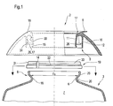
- FIG. 1 illustrates in a schematically highly simplified representation using Side views and partly axial sections the basic structure of the individual Elements for realizing a permanent connection 1 one Plastic fitting 2 on a glass container 3 in a view of the state before assembly.
- a glass container 3 is a coffee or Teapot 4
- the plastic fitting 2 is in the form of a pouring ring or Pouring rim 5 executed.
- the plastic fitting 2 can also take other forms.
- the glass container 3 has an opening 6 for receiving and dispensing filling medium into or out of the interior 7 of the glass container 3.
- the glass container 3 is designed in the region of the opening with a smaller diameter d 6 compared to the rest of the interior 7.
- the area in which the opening 6 is arranged functions as a receiving and / or dispensing area and is referred to as an opening area 8. In the functional position of the glass container 3, this generally extends in the vertical direction. Other directions are also conceivable.
- the plastic fitting 2, for example in the form of a pouring ring or pouring rim 5, is fixed in the opening area 8.
- the pouring ring or pouring rim 5 consists of plastic and encloses the wall 29 of the glass container 3 in the opening area 8 on both sides in the circumferential direction.
- the plastic fitting 2 can be designed differently with regard to the geometry. However, this preferably has an inner wall geometry in the enclosing area, which enables enclosing the opening area 8.
- two walls 11 and 12 which extend in a hollow cylinder and extend to the glass container 3, are provided on the inner circumference 16, which can also be referred to as a lip if the wall thickness is correspondingly small, these being molded onto the plastic fitting 2.
- the first hollow cylindrical wall 11, which extends toward the glass container is characterized by larger dimensions characterizing its outer circumference 30 than the inner circumference 18 of the glass container 3 in the opening area 8.
- the second wall 12, which extends towards the glass container encloses the glass container 3 on the outer circumference 20 in the opening area 8.
- Both walls are connected to one another in the vertical direction in the upper area 10 via the inner circumference 16 and delimit an intermediate space 13.
- the plastic fitting 2 has a fixing point in FIG a device for fixing the position and fastening 9 in the vertical direction.
- This comprises at least one circumferential projection 26, which is made in one piece with the plastic fitting 2, or a plurality of individual projections 26 which are arranged adjacent to one another in the circumferential direction and which can also be referred to as segments 17, and which extend on the inner circumference 31 of the second in the vertical direction towards the glass container 3 extending wall 12 are arranged and extend towards the wall 29 of the glass container 3 in the installed position.
- the device 9 comprises a wrapping element 19 which surrounds the glass container 3 in the opening area 8 in an area of smaller external dimensions 32 than at the opening 6 in the installed position.
- the looping element 19 is slotted, ie provided with an interruption 14 in the circumferential direction, in order to bring the looping element 19 into the installed position, ie to pull it over the opening area 8.
- the inner dimensions of the wrapping element 19 are selected such that it cannot be moved in the installed position without spreading the wrapping element 19 over the opening area 8 from the glass container.
- the glass container 3 and the opening area 8 are preferably designed with a circular cross section.
- the wrapping element 19 is then designed as an annular element 33. In order to achieve a positive connection with the projections 26 designed as a circumferential segment 17 or a plurality of segments 17, this has a groove 22 which is arranged on the outer circumference 21 and preferably extends in the circumferential direction over the entire circumference.
- the first wall 11 is in terms of its geometric configuration and Dimensioning selected such that it is touching when viewed in the installed position at least on part of the inner circumference 18 in the opening area 8 of FIG Opening 6 is present.
- Figures 2a and 2b illustrate in a schematically simplified representation using of axial sections the individual process steps in the assembly of the Connection 1 between a plastic fitting 2 and the glass container 3.
- FIG. 2a illustrates the slipping on of the wrap element 19, in particular of the annular element 33 on the glass container 3 in the Area of smaller external dimensions 32 of the opening area 8 in completed state.
- the groove 22 carries annular element 33 in terms of its geometry on the inner circumference 23 such is designed so that this with at least part of the inner circumference 23rd Formed surface 24 touches the outer periphery 20 of the glass container 3.
- the annular slotted element 33 is preferably also made of plastic manufactured.
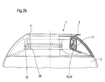
- FIG. 2b illustrates in a schematically simplified representation using a Axial baines the state of the connection 1 between the plastic fitting 2nd and the glass container 3 after sliding the plastic fitting 2 onto the Glass container 3. It can be seen that the segment 17 in the groove 22 in annular element 33 engages and thus positively connected to it becomes.
- the ring-shaped element 33 forms due to its internal geometry a kind of barb towards the part of the opening area 8, which is characterized by larger external dimensions than the area 32.
- the plastic fitting 2 is thus supported indirectly via the wrapping element 19 on the glass container 3. This connection 1 thus prevents a solution Connection in the vertical direction. This is only with the appropriate effort possible.
- the first wall 11 designed such that they touch the inner circumference 18 in the opening area 8 of the glass container 3 abuts.
- This area is designated 28.
- the wall For this purpose, 11 has elastic properties which are determined by the choice of material and / or dimensioning of the wall 11 are generated.
- the contact area 28 is executed by the end area 15 of the first wall 11 and the inner circumference 18 in the opening area 8 of the glass container 3.
- the wall of the plastic fitting 2 also lies on the glass container 3.
- FIG. 3b illustrates a second possible embodiment Realization of the seal between the plastic fitting 2 and the Glass container 3.
- the solution according to the invention enables the creation of a permanent one Connection 1 between a plastic fitting 2 and a glass container 3.
- This is characterized in that it is based on a combined in shape and when the wrapping element is supported on the glass container 3, in particular the wall 20, non-positive connection or one combined positive and material connection can be realized.
- This Connection is for filling media of the glass container with very high temperatures suitable without the resulting thermal Expansion of the materials a glass break in the area of the connection with the Plastic fittings would be feared.
- the solution to the connection is only possible by destroying it.
Landscapes
- Engineering & Computer Science (AREA)
- Food Science & Technology (AREA)
- Closures For Containers (AREA)
- Table Devices Or Equipment (AREA)
- Details Of Rigid Or Semi-Rigid Containers (AREA)
Abstract
Description
- Figur 1
- verdeutlicht in schematisch vereinfachter Darstellung den Grundaufbau der einzelnen Elemente der Verbindung;
- Figuren 2a und 2b
- zeigen in einer Ansicht gemäß Figur 1 den Zustand in Einbaulage nach den einzelnen Montageschritten;
- Figuren 3a und 3b
- verdeutlichen die erfindungsgemäße Verbindung 1 mit zusätzlichen Dichtmaßnahmen.
- 1
- Verbindung einer Kunststoffarmatur auf einem Glasbehälter
- 2
- Kunststoffarmatur
- 3
- Glasbehälter
- 4
- Kaffeekanne
- 5
- Gießring oder Schüttrand
- 6
- Öffnung des Glasbehälters
- 7
- Innenraum des Glasbehälters
- 8
- Öffnungsbereich
- 9
- Einrichtung zur Lagefixierung und Befestigung
- 10
- vertikal oberer Bereich
- 11
- hohlzylindrisch, sich in vertikaler Richtung zum Glasbehälter hin erstreckende Wand
- 12
- zweite hohlzylindrisch, sich in vertikaler Richtung zum Glasbehälter hin erstreckende Wand
- 13
- Innenraum
- 14
- Unterbrechung
- 15
- Endbereich
- 16
- Innenumfang der Kunststoffarmatur
- 17
- Segment
- 18
- Innenumfang des Glasbehälters
- 19
- Umschlingungselement
- 20
- Außenumfang des Glasbehälters im Öffnungsbereich 8
- 21
- Außenumfang des ringförmigen Elementes 19
- 22
- Nut
- 23
- Innenumfang des ringförmigen Elementes 19
- 24
- Fläche
- 25
- Dichtung
- 26
- Vorsprung
- 27 28
- Berührungsbereich
- 29
- Wand
- 30
- Außenumfang erste Wand
- 31
- Innenumfang zweite Wand
- 32
- Bereich geringer Außenabmessungen
- 33
- Ringförmiges Element
- d6
- Öffnungsdurchmesser ringförmigen Elementes 19
- s12
- Wandstärke der Wand 12
- s11
- Wandstärke der Wand 11
Claims (11)
- Verbindung (1) einer Kunststoffarmatur (2) auf einem Glasbehälter (3), umfassend1.1 einen Glasbehälter (3) mit einem eine Öffnung (6) tragenden Öffnungsbereich (8);1.2 eine Kunststoffarmatur (2) mit zwei die Wand (20) des Glasbehälters (3) im Öffnungsbereich (8) beidseitig in Umfangsrichtung umschließenden Wänden (11, 12)- eine erste innere Wand (11) und eine zweite äußere Wand (12);
gekennzeichnet durch die folgenden Merkmale:1.3 der Öffnungsbereich (8) weist einen Bereich geringerer Außenabmessungen am Außenumfang als an der Öffnung (6)auf;1.4 mit einem in Umfangsrichtung unterbrochenen Umschlingungselement (19), welches den Öffnungsbereich (8) im Bereich geringeren Querschnittes umschließt und sich an der Wand (20) des Glasbehälters (3) abstützt;1.5 die Kunststoffarmatur (2) ist formschlüssig mit dem Umschlingungselement (19) verbunden. - Verbindung (1) nach Anspruch 1, dadurch gekennzeichnet, daß der Formschluß zwischen Umschlingungselement (19) und Kunststoffarmatur (2) durch zueinander komplementäre Ausnehmungen (22) und Vorsprünge (26, 17) am Umschlingungselement (19) und am Innenumfang der zweiten äußeren Wand (12) der Kunststoffarmatur (2) erzeugt wird.
- Verbindung (1) nach Anspruch 2, dadurch gekennzeichnet, daß das Umschlingungselement (19) am Außenumfang eine in Umfangsrichtung verlaufende und um den Umfang erstreckende Nut (22) aufweist.
- Verbindung (1) nach einem der Ansprüche 2 oder 3, dadurch gekennzeichnet, daß am Innenumfang der zweiten Wand (12) ein in Umfangsrichtung verlaufender und sich über den Umfang erstreckender Vorsprung (26) in Form eines Segmentes (17) vorgesehen ist.
- Verbindung (1) nach einem der Ansprüche 2 oder 3, dadurch gekennzeichnet, daß am Innenumfang der zweiten Wand (12) wenigstens zwei in gleichmäßigen oder ungleichmäßigen Abständen zueinander in Umfangsrichtung angeordnete Vorsprünge (26) in Form von Segmenten (17) vorgesehen sind.
- Verbindung (1) nach einem der Ansprüche 2 bis 5, dadurch gekennzeichnet, daß die Vorsprünge (26) einteilig mit der Kunststoffarmatur (2) ausgeführt sind.
- Verbindung (1) nach einem der Ansprüche 1 bis 6, dadurch gekennzeichnet, daß er Öffnungsbereich (8) des Glasbehälters (3) einen kreisrunden Querschnitt aufweist und das Umschlingungselement (19) als geschlitztes ringförmiges Element (33) ausgeführt ist.
- Verbindung (1) nach einem der Ansprüche 1 bis 7, dadurch gekennzeichnet, daß zwischen der ersten Wand (11) der Kunststoffarmatur (2) und der Wand (20) des Glasbehälters (3) eine umlaufende berührende Dichtung (25) angeordnet ist.
- Verbindung (1) nach einem der Ansprüche 1 bis 7, dadurch gekennzeichnet, daß der Zwischenraum (13) zwischen beiden Wänden (11) und (12), der Wand (20) des Glasbehälters (3) und dem Umschlingungselement (19) mit einem aushärtendem und an den Anschlusselementen haftendem Füllmedium befüllt ist.
- Verbindung (1) nach einem der Ansprüche 1 bis 9, dadurch gekennzeichnet, daß die erste innere Wand (11) elastisch ausgeführt ist, so daß diese in Einbaulage mit wenigstens einem Teil ihrer Fläche am Außenumfang am Innenumfang des Glasbehälters (3) im Öffnungsbereich (8) anliegt.
- Behältnis zur Aufnahme und Abgabe von Füllmedien, insbesondere Teeoder Kaffeekanne oder Wasserkochglas;11.1 mit einem Glasbehälter (3) mit wenigstens einer Öffnung (6);11.2 mit einer der Öffnung (6) zugeordneten Kunststoffarmatur (2);11.3 mit einer Verbindung (1) gemäß einem der Ansprüche 1 bis 10 der Kunststoffarmatur (2) auf dem Glasbehälter (3).
Applications Claiming Priority (2)
| Application Number | Priority Date | Filing Date | Title |
|---|---|---|---|
| DE10209107A DE10209107A1 (de) | 2002-03-01 | 2002-03-01 | Verfahren zum dauerhaften Verbinden einer Kunststoffarmatur auf einem Glasbehälter |
| DE10209107 | 2002-03-01 |
Publications (3)
| Publication Number | Publication Date |
|---|---|
| EP1350734A2 true EP1350734A2 (de) | 2003-10-08 |
| EP1350734A3 EP1350734A3 (de) | 2003-12-10 |
| EP1350734B1 EP1350734B1 (de) | 2005-11-23 |
Family
ID=27762588
Family Applications (1)
| Application Number | Title | Priority Date | Filing Date |
|---|---|---|---|
| EP03003516A Expired - Lifetime EP1350734B1 (de) | 2002-03-01 | 2003-02-15 | Verbinden einer Kunststoffarmatur auf einem Glasbehälter |
Country Status (5)
| Country | Link |
|---|---|
| US (1) | US7163131B2 (de) |
| EP (1) | EP1350734B1 (de) |
| CN (1) | CN1304245C (de) |
| AT (1) | ATE310681T1 (de) |
| DE (2) | DE10209107A1 (de) |
Families Citing this family (1)
| Publication number | Priority date | Publication date | Assignee | Title |
|---|---|---|---|---|
| US7731054B1 (en) * | 2004-05-21 | 2010-06-08 | Food Equipment Technologies Company, Inc. | Beverage urn with handle assembly |
Family Cites Families (8)
| Publication number | Priority date | Publication date | Assignee | Title |
|---|---|---|---|---|
| US3154227A (en) * | 1961-09-25 | 1964-10-27 | Farmer Bros Co | Decanter with pouring spout and seal |
| US3330449A (en) * | 1965-08-25 | 1967-07-11 | Bloomfield Ind Inc | Decanter with detachable spout |
| US4090648A (en) * | 1976-04-09 | 1978-05-23 | Bloomfield Industries, A Division Of Beatrice Foods Co. | Decanter and molded interlocking handle |
| US4838463A (en) * | 1987-04-15 | 1989-06-13 | Bloomfield Industries, Inc. | Decanter with molded interlocking handle |
| DE3926760A1 (de) * | 1989-08-12 | 1991-02-14 | Schott Glaswerke | Hotelkanne |
| DE3937461A1 (de) * | 1989-11-10 | 1991-05-16 | Bentz & Sohn Melitta | Glaskanne mit einem griff |
| US5224634A (en) * | 1991-05-20 | 1993-07-06 | Wilbur Curtis Company, Inc. | Decanter vessel and pouring spout |
| GB2362804B (en) * | 2000-04-05 | 2002-04-17 | Kenwood Marks Ltd | Decanter vessels |
-
2002
- 2002-03-01 DE DE10209107A patent/DE10209107A1/de not_active Withdrawn
-
2003
- 2003-02-15 EP EP03003516A patent/EP1350734B1/de not_active Expired - Lifetime
- 2003-02-15 DE DE50301713T patent/DE50301713D1/de not_active Expired - Fee Related
- 2003-02-15 AT AT03003516T patent/ATE310681T1/de not_active IP Right Cessation
- 2003-02-28 US US10/376,714 patent/US7163131B2/en not_active Expired - Fee Related
- 2003-03-01 CN CNB031105041A patent/CN1304245C/zh not_active Expired - Fee Related
Also Published As
| Publication number | Publication date |
|---|---|
| CN1304245C (zh) | 2007-03-14 |
| HK1055416A1 (en) | 2004-01-09 |
| US20040011799A1 (en) | 2004-01-22 |
| US7163131B2 (en) | 2007-01-16 |
| DE50301713D1 (de) | 2005-12-29 |
| CN1442344A (zh) | 2003-09-17 |
| EP1350734A3 (de) | 2003-12-10 |
| EP1350734B1 (de) | 2005-11-23 |
| DE10209107A1 (de) | 2003-09-18 |
| ATE310681T1 (de) | 2005-12-15 |
Similar Documents
| Publication | Publication Date | Title |
|---|---|---|
| DE3036139C2 (de) | ||
| EP2114816A2 (de) | Keg | |
| EP1852390B1 (de) | Absperrorgan für einen Behälter, insbesondere Palettenbehälter | |
| DE102007039106A1 (de) | Anschlussteil zur Verbindung einer Materialzuführungseinrichtung an eine Spritzpistole | |
| EP2340212A1 (de) | Verschluss zum aufschrauben auf einen behälter | |
| EP1030097B1 (de) | Anschlussarmatur mit einem Armaturkörper mit drehbarer Befestigung | |
| EP3382239B1 (de) | Verschliessbare behälter-anordnung | |
| DE19505142C2 (de) | Behälterverschluß | |
| DE60001412T2 (de) | Flaschenverschluss | |
| DE60013728T2 (de) | Vorrichtung zum Verschliessen von Flaschen, die unter Druck stehende Feüssigkeiten enthalten | |
| EP1350734B1 (de) | Verbinden einer Kunststoffarmatur auf einem Glasbehälter | |
| DE4416448C2 (de) | Behälter mit einer Schraubkappe für Nagellack, Mascaraflüssigkeit o. dgl. | |
| DE202009000057U1 (de) | Montagesystem | |
| DE102018123514B4 (de) | Anordnung mit einer dichten, lösbaren Verbindung eines Flaschenhalsgewindes mit einem Flaschenhalsverschluss | |
| DE102008061415A1 (de) | Medizingeräteschlauchkonnektor | |
| DE69901883T2 (de) | Befestigungselement einer spendevorrichtung zur befestigung auf dem hals eines behälters, spendevorrichtung mit einem solchen befestigungselement und verfahren zur befestigung | |
| EP3839299A1 (de) | Radialwellendichtung, faltenbalgflansch und montageverfahren hierfür | |
| EP3145830B1 (de) | Behälterverschluss | |
| DE20120142U1 (de) | Sprühdose | |
| EP3268290B1 (de) | Dosier- und ausgiessvorrichtung für fliessfähige substanzen und mit einer derartigen dosier- und ausgiessvorrichtung ausgestatteter behälter | |
| DE10244873B4 (de) | Verschluss für einen Füllstutzen mit Dichtung | |
| AT519670B1 (de) | Verschlussanordnung für einen Verpackungsbehälter sowie daraus gebildete Verpackungseinheit | |
| DE4114608C1 (de) | ||
| DE3000784A1 (de) | Kugelauftragsvorrichtung, insbesondere fuer ausquetschbare tubenfoermige behaelter | |
| DE102007029645B4 (de) | Flaschenverschluss mit Abdichthülse |
Legal Events
| Date | Code | Title | Description |
|---|---|---|---|
| PUAI | Public reference made under article 153(3) epc to a published international application that has entered the european phase |
Free format text: ORIGINAL CODE: 0009012 |
|
| AK | Designated contracting states |
Kind code of ref document: A2 Designated state(s): AT BE BG CH CY CZ DE DK EE ES FI FR GB GR HU IE IT LI LU MC NL PT SE SI SK TR |
|
| AX | Request for extension of the european patent |
Extension state: AL LT LV MK RO |
|
| PUAL | Search report despatched |
Free format text: ORIGINAL CODE: 0009013 |
|
| AK | Designated contracting states |
Kind code of ref document: A3 Designated state(s): AT BE BG CH CY CZ DE DK EE ES FI FR GB GR HU IE IT LI LU MC NL PT SE SI SK TR |
|
| AX | Request for extension of the european patent |
Extension state: AL LT LV MK RO |
|
| RIC1 | Information provided on ipc code assigned before grant |
Ipc: 7A 47J 45/06 B Ipc: 7B 65D 51/14 A Ipc: 7B 65D 23/00 B Ipc: 7A 47G 19/14 B |
|
| 17P | Request for examination filed |
Effective date: 20031213 |
|
| AKX | Designation fees paid |
Designated state(s): AT BE BG CH CY CZ DE DK EE ES FI FR GB GR HU IE IT LI LU MC NL PT SE SI SK TR |
|
| 17Q | First examination report despatched |
Effective date: 20040820 |
|
| RAP1 | Party data changed (applicant data changed or rights of an application transferred) |
Owner name: SCHOTT AG |
|
| GRAP | Despatch of communication of intention to grant a patent |
Free format text: ORIGINAL CODE: EPIDOSNIGR1 |
|
| GRAS | Grant fee paid |
Free format text: ORIGINAL CODE: EPIDOSNIGR3 |
|
| GRAA | (expected) grant |
Free format text: ORIGINAL CODE: 0009210 |
|
| AK | Designated contracting states |
Kind code of ref document: B1 Designated state(s): AT BE BG CH CY CZ DE DK EE ES FI FR GB GR HU IE IT LI LU MC NL PT SE SI SK TR |
|
| PG25 | Lapsed in a contracting state [announced via postgrant information from national office to epo] |
Ref country code: IE Free format text: LAPSE BECAUSE OF FAILURE TO SUBMIT A TRANSLATION OF THE DESCRIPTION OR TO PAY THE FEE WITHIN THE PRESCRIBED TIME-LIMIT Effective date: 20051123 Ref country code: SK Free format text: LAPSE BECAUSE OF FAILURE TO SUBMIT A TRANSLATION OF THE DESCRIPTION OR TO PAY THE FEE WITHIN THE PRESCRIBED TIME-LIMIT Effective date: 20051123 Ref country code: CZ Free format text: LAPSE BECAUSE OF FAILURE TO SUBMIT A TRANSLATION OF THE DESCRIPTION OR TO PAY THE FEE WITHIN THE PRESCRIBED TIME-LIMIT Effective date: 20051123 Ref country code: FI Free format text: LAPSE BECAUSE OF FAILURE TO SUBMIT A TRANSLATION OF THE DESCRIPTION OR TO PAY THE FEE WITHIN THE PRESCRIBED TIME-LIMIT Effective date: 20051123 Ref country code: SI Free format text: LAPSE BECAUSE OF FAILURE TO SUBMIT A TRANSLATION OF THE DESCRIPTION OR TO PAY THE FEE WITHIN THE PRESCRIBED TIME-LIMIT Effective date: 20051123 Ref country code: NL Free format text: LAPSE BECAUSE OF FAILURE TO SUBMIT A TRANSLATION OF THE DESCRIPTION OR TO PAY THE FEE WITHIN THE PRESCRIBED TIME-LIMIT Effective date: 20051123 |
|
| REG | Reference to a national code |
Ref country code: GB Ref legal event code: FG4D Free format text: NOT ENGLISH |
|
| REG | Reference to a national code |
Ref country code: CH Ref legal event code: EP |
|
| GBT | Gb: translation of ep patent filed (gb section 77(6)(a)/1977) | ||
| REF | Corresponds to: |
Ref document number: 50301713 Country of ref document: DE Date of ref document: 20051229 Kind code of ref document: P |
|
| REG | Reference to a national code |
Ref country code: IE Ref legal event code: FG4D Free format text: LANGUAGE OF EP DOCUMENT: GERMAN |
|
| REG | Reference to a national code |
Ref country code: SE Ref legal event code: TRGR |
|
| PG25 | Lapsed in a contracting state [announced via postgrant information from national office to epo] |
Ref country code: AT Free format text: LAPSE BECAUSE OF NON-PAYMENT OF DUE FEES Effective date: 20060215 |
|
| PG25 | Lapsed in a contracting state [announced via postgrant information from national office to epo] |
Ref country code: BG Free format text: LAPSE BECAUSE OF FAILURE TO SUBMIT A TRANSLATION OF THE DESCRIPTION OR TO PAY THE FEE WITHIN THE PRESCRIBED TIME-LIMIT Effective date: 20060223 Ref country code: DK Free format text: LAPSE BECAUSE OF FAILURE TO SUBMIT A TRANSLATION OF THE DESCRIPTION OR TO PAY THE FEE WITHIN THE PRESCRIBED TIME-LIMIT Effective date: 20060223 Ref country code: GR Free format text: LAPSE BECAUSE OF FAILURE TO SUBMIT A TRANSLATION OF THE DESCRIPTION OR TO PAY THE FEE WITHIN THE PRESCRIBED TIME-LIMIT Effective date: 20060223 |
|
| PG25 | Lapsed in a contracting state [announced via postgrant information from national office to epo] |
Ref country code: BE Free format text: LAPSE BECAUSE OF NON-PAYMENT OF DUE FEES Effective date: 20060228 Ref country code: MC Free format text: LAPSE BECAUSE OF NON-PAYMENT OF DUE FEES Effective date: 20060228 Ref country code: LU Free format text: LAPSE BECAUSE OF NON-PAYMENT OF DUE FEES Effective date: 20060228 |
|
| PG25 | Lapsed in a contracting state [announced via postgrant information from national office to epo] |
Ref country code: ES Free format text: LAPSE BECAUSE OF FAILURE TO SUBMIT A TRANSLATION OF THE DESCRIPTION OR TO PAY THE FEE WITHIN THE PRESCRIBED TIME-LIMIT Effective date: 20060306 |
|
| PG25 | Lapsed in a contracting state [announced via postgrant information from national office to epo] |
Ref country code: PT Free format text: LAPSE BECAUSE OF FAILURE TO SUBMIT A TRANSLATION OF THE DESCRIPTION OR TO PAY THE FEE WITHIN THE PRESCRIBED TIME-LIMIT Effective date: 20060424 |
|
| NLV1 | Nl: lapsed or annulled due to failure to fulfill the requirements of art. 29p and 29m of the patents act | ||
| PG25 | Lapsed in a contracting state [announced via postgrant information from national office to epo] |
Ref country code: HU Free format text: LAPSE BECAUSE OF FAILURE TO SUBMIT A TRANSLATION OF THE DESCRIPTION OR TO PAY THE FEE WITHIN THE PRESCRIBED TIME-LIMIT Effective date: 20060524 |
|
| REG | Reference to a national code |
Ref country code: IE Ref legal event code: FD4D |
|
| ET | Fr: translation filed | ||
| PLBE | No opposition filed within time limit |
Free format text: ORIGINAL CODE: 0009261 |
|
| STAA | Information on the status of an ep patent application or granted ep patent |
Free format text: STATUS: NO OPPOSITION FILED WITHIN TIME LIMIT |
|
| 26N | No opposition filed |
Effective date: 20060824 |
|
| PG25 | Lapsed in a contracting state [announced via postgrant information from national office to epo] |
Ref country code: LI Free format text: LAPSE BECAUSE OF NON-PAYMENT OF DUE FEES Effective date: 20070228 Ref country code: CH Free format text: LAPSE BECAUSE OF NON-PAYMENT OF DUE FEES Effective date: 20070228 |
|
| REG | Reference to a national code |
Ref country code: CH Ref legal event code: PL |
|
| BERE | Be: lapsed |
Owner name: SCHOTT A.G. Effective date: 20060228 |
|
| PGFP | Annual fee paid to national office [announced via postgrant information from national office to epo] |
Ref country code: DE Payment date: 20080219 Year of fee payment: 6 Ref country code: GB Payment date: 20080220 Year of fee payment: 6 Ref country code: IT Payment date: 20080223 Year of fee payment: 6 Ref country code: SE Payment date: 20080214 Year of fee payment: 6 |
|
| PG25 | Lapsed in a contracting state [announced via postgrant information from national office to epo] |
Ref country code: EE Free format text: LAPSE BECAUSE OF FAILURE TO SUBMIT A TRANSLATION OF THE DESCRIPTION OR TO PAY THE FEE WITHIN THE PRESCRIBED TIME-LIMIT Effective date: 20051123 |
|
| PG25 | Lapsed in a contracting state [announced via postgrant information from national office to epo] |
Ref country code: TR Free format text: LAPSE BECAUSE OF FAILURE TO SUBMIT A TRANSLATION OF THE DESCRIPTION OR TO PAY THE FEE WITHIN THE PRESCRIBED TIME-LIMIT Effective date: 20051123 |
|
| PGFP | Annual fee paid to national office [announced via postgrant information from national office to epo] |
Ref country code: FR Payment date: 20080214 Year of fee payment: 6 |
|
| PG25 | Lapsed in a contracting state [announced via postgrant information from national office to epo] |
Ref country code: CY Free format text: LAPSE BECAUSE OF FAILURE TO SUBMIT A TRANSLATION OF THE DESCRIPTION OR TO PAY THE FEE WITHIN THE PRESCRIBED TIME-LIMIT Effective date: 20051123 |
|
| EUG | Se: european patent has lapsed | ||
| GBPC | Gb: european patent ceased through non-payment of renewal fee |
Effective date: 20090215 |
|
| REG | Reference to a national code |
Ref country code: FR Ref legal event code: ST Effective date: 20091030 |
|
| PG25 | Lapsed in a contracting state [announced via postgrant information from national office to epo] |
Ref country code: DE Free format text: LAPSE BECAUSE OF NON-PAYMENT OF DUE FEES Effective date: 20090901 |
|
| PG25 | Lapsed in a contracting state [announced via postgrant information from national office to epo] |
Ref country code: GB Free format text: LAPSE BECAUSE OF NON-PAYMENT OF DUE FEES Effective date: 20090215 Ref country code: FR Free format text: LAPSE BECAUSE OF NON-PAYMENT OF DUE FEES Effective date: 20090302 |
|
| PG25 | Lapsed in a contracting state [announced via postgrant information from national office to epo] |
Ref country code: IT Free format text: LAPSE BECAUSE OF NON-PAYMENT OF DUE FEES Effective date: 20090215 |
|
| PG25 | Lapsed in a contracting state [announced via postgrant information from national office to epo] |
Ref country code: SE Free format text: LAPSE BECAUSE OF NON-PAYMENT OF DUE FEES Effective date: 20090216 |