EP1350462B1 - Système d'ensemble d'élecctrodes permettant de mesurer des signaux électrophysiologiques - Google Patents
Système d'ensemble d'élecctrodes permettant de mesurer des signaux électrophysiologiques Download PDFInfo
- Publication number
- EP1350462B1 EP1350462B1 EP03010436A EP03010436A EP1350462B1 EP 1350462 B1 EP1350462 B1 EP 1350462B1 EP 03010436 A EP03010436 A EP 03010436A EP 03010436 A EP03010436 A EP 03010436A EP 1350462 B1 EP1350462 B1 EP 1350462B1
- Authority
- EP
- European Patent Office
- Prior art keywords
- array
- electrodes
- electrode
- electrical signals
- connector
- Prior art date
- Legal status (The legal status is an assumption and is not a legal conclusion. Google has not performed a legal analysis and makes no representation as to the accuracy of the status listed.)
- Expired - Lifetime
Links
Images


Classifications
-
- A—HUMAN NECESSITIES
- A61—MEDICAL OR VETERINARY SCIENCE; HYGIENE
- A61B—DIAGNOSIS; SURGERY; IDENTIFICATION
- A61B5/00—Measuring for diagnostic purposes; Identification of persons
- A61B5/24—Detecting, measuring or recording bioelectric or biomagnetic signals of the body or parts thereof
- A61B5/30—Input circuits therefor
-
- A—HUMAN NECESSITIES
- A61—MEDICAL OR VETERINARY SCIENCE; HYGIENE
- A61B—DIAGNOSIS; SURGERY; IDENTIFICATION
- A61B5/00—Measuring for diagnostic purposes; Identification of persons
- A61B5/24—Detecting, measuring or recording bioelectric or biomagnetic signals of the body or parts thereof
- A61B5/25—Bioelectric electrodes therefor
- A61B5/279—Bioelectric electrodes therefor specially adapted for particular uses
- A61B5/28—Bioelectric electrodes therefor specially adapted for particular uses for electrocardiography [ECG]
- A61B5/282—Holders for multiple electrodes
-
- A—HUMAN NECESSITIES
- A61—MEDICAL OR VETERINARY SCIENCE; HYGIENE
- A61B—DIAGNOSIS; SURGERY; IDENTIFICATION
- A61B5/00—Measuring for diagnostic purposes; Identification of persons
- A61B5/24—Detecting, measuring or recording bioelectric or biomagnetic signals of the body or parts thereof
- A61B5/25—Bioelectric electrodes therefor
- A61B5/279—Bioelectric electrodes therefor specially adapted for particular uses
- A61B5/291—Bioelectric electrodes therefor specially adapted for particular uses for electroencephalography [EEG]
-
- A—HUMAN NECESSITIES
- A61—MEDICAL OR VETERINARY SCIENCE; HYGIENE
- A61B—DIAGNOSIS; SURGERY; IDENTIFICATION
- A61B2560/00—Constructional details of operational features of apparatus; Accessories for medical measuring apparatus
- A61B2560/04—Constructional details of apparatus
- A61B2560/0443—Modular apparatus
- A61B2560/045—Modular apparatus with a separable interface unit, e.g. for communication
-
- A—HUMAN NECESSITIES
- A61—MEDICAL OR VETERINARY SCIENCE; HYGIENE
- A61B—DIAGNOSIS; SURGERY; IDENTIFICATION
- A61B2562/00—Details of sensors; Constructional details of sensor housings or probes; Accessories for sensors
- A61B2562/22—Arrangements of medical sensors with cables or leads; Connectors or couplings specifically adapted for medical sensors
- A61B2562/225—Connectors or couplings
- A61B2562/227—Sensors with electrical connectors
Definitions
- This invention relates to physiological electrical signal monitors and more particularly to a self-prepping multiple electrode array to connect to such monitors.
- Surgical procedures are becoming more non-invasive, and as a result the use of non-invasive electrophysiological monitoring to evaluate global changes of a patient's condition during surgical procedures has increased significantly.
- EEG monitors are now being used for monitoring cerebral function during intra-operative procedures.
- assessments of the effects, of anesthetics are now being used for monitoring cerebral function during intra-operative procedures.
- assessments of the effects, of anesthetics are now being used for monitoring cerebral function during intra-operative procedures.
- headsets and caps are studded with different style electrodes to speed this process, but such headsets and caps are generally not disposable (and therefore must be cleaned), need to be adjusted to accommodate the widely varying dimensions of the patients' heads, and require a considerable up-front cost.
- Other problems are encountered in the present medical environment when such headsets and caps are designed to be single-use disposable devices because such devices are on occasion re-used despite warnings, which may results in the spread of infection.
- Such headsets and caps have also been used with equipment for which it was not designed, which may be a well intentioned cost saving practice, but which could result in degraded performance of the device.
- the most widely used electrodes are the reusable "gold cup” style electrodes that are small, bare tin, silver. or gold plated metal cups on the end of unshielded wires that may be several feet long. Such electrodes may require that the multiple scalp and forehead electrode sites first be located by measuring and marking the head. Such sites must then be prepared before applying the electrode in order to get good electrical contact. This preparation is usually accomplished by abrading the electrode sites with a gril-impregnated solution or with some other abrasive means to remove the outer layers of skin which cause the poor electrical contact.
- the electrodes up to 19 on the scalp for the full International (10-20) electrode placement, are then individually applied with adhesive to the prepared sites in contact with a blood-enriched skin layer, and are then injected with conductive electrolyte cream through the hole in the top of the electrode, thereby providing a relatively low electrical contact impedance. This process leaves the patient with abraded spots, adhesive, and electrolyte cream throughout the scalp. Frequently, contact between the metal electrode and the skin occurs, causing a time-varying offset voltage that results in "baseline wander.”
- the electrodes also need to be placed with reasonable accuracy to achieve the standard placements or montages and to be able to repeat the same measurement at a later time
- U.S. Patent No. 4,936,306 issued to Doty utilizes a spiral coil electrode that may be metallic, and that uses cork-screws into patient's skin to achieve low contact impedance. While this may achieve low contact impedance, it has the significant drawbacks of discomfort to the patient and creating sites of possible infection because of the deep skin punctures made by the spiral coils. If made of metal, the spiral coits will also cause time-varying voltages. Lastly, these electrodes are actually applied individually since they must be screwed into the patient's scalp, which adds time to the procedure.
- U.S. Patent No. 4,683,892 issued to Johansson utilizes a headset with multiple electrodes that are activated by compressed air, which impinge against the patient's scalp, and that also dispense electrolyte paste to improve contact. This is a complex and expensive device, not intended for general, routine use in an intraoperative environment.
- WO-A-9 611 631 discloses an array according to the preamble of claim 1.
- Another object of the present invention is to provide a self-prepping multiple electrode array that does not require the use of more than one component to be handled by the person applying the device, and fits most head sizes in the general patient population.
- Still another object of the present invention is to provide a multiple electrode array that can monitor cerebral function without the use of electrodes placed in the scalp, and that is easily aligned on the head.
- a further object of the present invention is to provide a multiple electrode array that prevents its use with monitoring equipment with which it was not intended to be used.
- An array of electrodes is constructed to allow the userto easily adjust to the correct size of the patient's head.
- the array is self-adhesive, pre-gelled and disposable.
- the array fits easily over the temple and forehead areas where EEG signals can be acquired by specially designed monitors for purposes of monitoring a number of bodily phenomena, including but not limited to, depth of anesthesia, and/or ischemia, and burst suppression.
- the array is connected to the monitor via a tab connector that is integral to the disposable device.
- the tab connector is insertible into a reusable connector that is part of a monitoring system.
- the reusable connector is made of rigid contacts positioned side by side within a keyed cavity. The contacts press against conductors of the disposable array when the conductors are inserted into the cavity of the reusable connector.
- the conductors of the disposable array are laid on a flexible circuit constructed of a polyester substrate that has a plastic clip as its backing and support. The flexible circuit when routed through this clip forms the tab connector.
- This sensor tab connector when inserted into the reusable connector cavity, electrically connects the electrodes to the monitor, allowing the acquisition of the electrophysiological signals.
- the clip of the tab connector is self securing, and thus does not need any additional securing mechanism to keep the flexible circuit in place.
- the reusable connector and the disposable connector have complementary locking mechanisms that provide for a secure connection.
- a tab connector may be used which includes a key that only fits to specific monitors.
- the array also can communicate with the monitor to indicate the type of application utilizing the electrodes and how many channels need to be configured.
- the array contains two or more elements that when pressed against the skin lower their contact impedance to the skin and thus provide better quality signals.
- the elements contain built in blowout pockets that allow for the gel to adjust itself when pressure is applied to it. Such pockets also prevent the gel from getting blown into the adhesive areas or running into other element areas, which could cause channels to short circuit
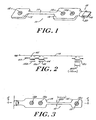
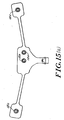
- an electrode array 10 is shown.
- the array 10 includes three electrodes 12 that are Self adherent and self prepping to the forehead and temple areas and that are used to acquire electrophysiological(EEG) signals.
- This array 10 comprises a flexible circuit containing silver/silver-chloride (Ag/AgCl) conductors 16 on a polyester substrate. These conductors are routed from specific montage locations to a single connecting tab 18. There can be up to eight (8) conductors 16 for providing up to eight signal lines of EEG data which can be captured simultaneously.
- This tab 18 contains a clip 20 which adds rigidity, a locking mechanism, self alignment, polarity and a keying mechanism to the array. The dip 20 also adds a solid contact area to the flexible circuit.
- the array 10 comprises a main body 14 which in the embodiment shown includes two electrodes 12a, 12b and a satellite body 15 which includes one electrode 12c.
- the satellite body 15 allows the monitoring personnel to adjust the placement of the electrode 12c mounted on the satellite body 15 due to the patient's head size.
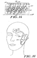
- each of the three electrodes 12 mounted in the array 10 contain a self prepping disk 30 which includes a set of flexible tines 44 mounted with adhesive 45.
- the flexible tines 44 extended beyond the surface of the gel 40 to contact the skin 32 as part of the normal application of the electrode 12 to the skin 32.
- the flexible lines 44 are pushed through foam layer 42 against the skin 32, which causes the tines 44 to part the high impedance outer layers of skin 32 to exposa the low impedance, blood-enriched layers without scratching or abrading.
- This prepping disk is made out of a plastic such as nylon constructed as hooks from hook and loop fasteners of the type often said under the Velcro trademark. These hooks are then sheared to the correct height and stiffness.
- the electrodes 12 are surrounded by an adhesive backed foam layer 43.
- the array contains markers 13 that indicate the correct locations that need to be pressed to achieve the desired skin impedance.
- the array contains two blowout pockets 38, built into the basepad 39, that allow the gel 40 to adjust its volume over a large area and prevent it from migrating to areas where it could cause malfunction, such as short circuiting the two elements adjacent to one another.
- the blowout pockets 38 are formed by cutting cylindrical shapes into the basepad 39 foam material.
- the array 10 also contains two salt bridge barriers 46 which prevent electrolyte gel 40 from one electrode from contacting the gel 40 of the other electrode which could cause the signals to short circuit.
- the barriers 46 are also cut into the adhesive basepad 39.
- a liquid hydrogel is used that rests on the gel pockets 38 cut within the basepad material 39.
- the gel 40 is retained within the pocket by a polyurethane foam sponge 42.
- the sponge contains large enough pores that allow the tines 44 to go through the pores and contact the skin 32 during use. The tines 44 then work in the same manner as described in U.S. Patent No. 5,305,746.
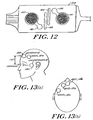
- the array 10 is mounted over the forehead with its reference electrode 12b over the center of the forehead. As shown in Figures 13(a) and 13(b), the ground electrode 12a is placed over the forehead as well.
- the third electrode 12c in the satellite body 15 is positioned over the temple area. In most cases, either the right or left temple is acceptable. Such an array may also be used for EMG detection in the facial area.
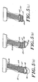
- the tab connector of the present invention is shown in Figures 5(a)-5(c).
- Figure 5(a) the conductors 16 which are mounted on a flexible material are inserted into the clip 20 past the edge 46 of the clip 20.
- the dip 20 includes a hinge 47 which is folded back as shown in Figure 5(b) until it is rotated a full one hundred eighty degrees as shown in Figure 5(c).
- a slot 48 is provided on each side of dip 20 for locking with extension 49 so that the dip 20 stays in a locked and closed position as shown in Figure 5(c), so that it is ready to be used.
- the tab connector 18 of the array 10 of the preferred embodiment has eight (8) conductors. Out of the eight conductors, three are EEG signal lines 16a, 16b, 16c, and four are logical signal lines 16e, 16f, 16g, 16h used to identify the appropriate array type being connected. In the embodiment shown, the eighth conductor 16d is not used. The unused conductor 16d could be used in other embodiments as an additional EEG signal line oras an additional means to identify an array type. It is important that the sensorsends the identification information to the monitor, so that the monitor can determine the number of active elements used as well as their locations on the head. This way a monitor will auto configure for a particular EEG monitoring session.
- the preferred embodiment uses a three bit binary code identification scheme such as the identification scheme described in United States Patent 5,813,404 which is assigned to the assignee of the present invention
- the code is hard-wired in the flexible circuit of the particular array 10.
- a digital signal converter in the monitor detects the array identification (ID) signals.
- the code is set by selectively shorting a common drive signal line (SEN_DRV) 60 to the three code signal lines [SEN_0:2] 62, 64, 66. These are the three array identification signal lines.
- the [SEN_DRV] line is pulsed (driven) to a logic high at 8,192Hz by the pulse generator located on a monitor's digital signal converter. Pulsing the line prevents a fault condition, such as a broken connection, from injecting more than 50 micro amps of current into a patient, as required by medical equipment standards, such as IEC-601-1.
- the frequency of the pulse is chosen to be at the Nyquist frequency of the digitizers. These pulses will not interfere with the EEG signal because at this frequency it will alias onto itself only in the first stage of decimation, and will subsequently be filtered out completely by the digital signal processor.
- the patient interface connector code signal lines are pulled down to a logic "0" by resistors 70, 72, 74 located in the digital signal converter 146 at the input to the receiver circuit 76, which is a D-Flip-flop in a preferred embodiment.
- the receiver circuit 76 As the common [SEN_DRV] line 60 is driven high by the pulse generator, the patient interface connector code lines [SEN_0:2] 62, 64, 66 are then read (i.e. docked in) by receiver circuit 76, which transmits the binary code to the monitor 150.
- the patient interface connector code signal lines that are shorted to the drive signal will be read as a logic "1.”
- the patient interface connector code signal lines that are left open will be read as a logic "0.”
- Such a coding scheme allows for eight different PIC cable types as follows: # Code (PIC ID) Cable Type 1 000 PIC not connected 2 001 2 channel Bipolar (5 signal wires in use) 3 010 2 channel Referential (4 signal wires in use) 4 011 1 channel electrode connection 5 100 1 channel sensor connection 6,7,8 Unassigned Spares
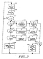
- a CPU in the monitor 150 periodically reads the PIC code, which in a preferred embodiment is read every 1.75 seconds.
- the CPU in monitor 150 reads a PIC ID in the manner described above with reference to Fig. 8. If the PIC ID is determined in step 86 to be "000,” (which indicates that a PIC is not connected) the system reiterates the process after each 1.75 second delay and continues to attempt to read a new PIC ID.
- step 88 If the PIC ID is determined in step 88 to be "010,” a two channel referential EEG electrode set is detected and the monitor 150 is configured for 2-channel referential EEG processing in step 90.
- the digital signal convertor is set to referential mode in step 92. If, in step 94, the PIC ID is equal to "001,” the system recognizes a two channel bipolar EEG electrode set and the monitor 150 is configured for the appropriate EEG processing in step 96.
- the digital signal convertor 148 is then set in step 98 to bipolar mode.
- step 100 If the PIC ID is determined in step 100 to be equal to "011," the system has detected a one channel EEG processing cable and the monitor 150 is configured for 1-channel EEG processing in step 102.
- step 106 digital signal converter is set to bipolar mode. If any other PIC ID is detected, error messages are generated and displayed in step 109 indicating that an illegal PIC ID was detected, and that no EEG processing should occur.
- the monitor checks in step 107 if the PIC ID is a new PIC ID. If a new PIC ID is recognized the monitor inltiates a self test in step 108 followed by an electrode impedance test. After this series of steps the system again returns after a 1.75 second delay to read additional PIC IDs in step 82.
- the digital signal convertor 146 can recognize up to 15 different combinations of pigtail, PIC or connector type.
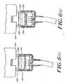
- the current connector system allows either a single channel electrode array or a dual channel electrode array. As shown in Figures 7(a)-7(e), it also provides a keying safeguard that allows for the connector to be selective as to what can physically be plugged into it. By modifying the height of the connector rails 50 one can allow for a specific array to be a master key ( Figure 7(a)) and other arrays to be specific to a mating connector.
- This keying mechanism can be used for example to physically differentiate between array types. For instance, an array that allows single and dual channel monitoring, and one that allows only dual channel monitoring.
- the master key is then available to connect to all monitors indiscriminately. For instance, it can be used to insert a test circuit to service the monitor, or used to insert a multipurpose array.
- the tab connection on the array has a locking mechanism, including extension 120 and receptor region 122 that secures it to the reusable connector 124.
- the locking action provides the user with tactile and audible feedback.
- the reusable connector 124 includes a printed circuit board with contacts and wires from a cable attached to it.
- the printed circuit board is then inserted into an assembly of two pre-molded housings secured together by ultrasonic welding.
- the electrode array 10 described above is used in connection with a new non-standard electrode positioning (montage) for measuring the effects of anesthetics on the brain as well as other cerebral phenomena.
- this montage is shown in which the reference electrode 12b is placed in the center of the forehead with the satellite electrode 12c being placed on the temple at eye level above the ear.
- This montage has several advantages over previously described montages, as it makes it easy to locate the electrodes on the patient, the electrodes are easy to apply to the patient and the EEG signal and the amplitude of such signal are sufficient for the purposes for which they are used.
- the location of the electrodes is important for monitoring the effects of anesthetics.
- Prior art for monitoring the effects of anesthetics have described EEG systems using from 2 to 19 EEG channels, where the electrode locations have been identified by the international 10-20 systems.
- the electrode arrays described above use 1 or 2 EEG channels.
- the specific electrode loeatians described in this patent are positioned in a unique anterior area of the subject's head from which EEG signals have not traditionally been taken. These anterior placed arrays take advantage of the global nature of the effects of anestheties on the brain. That is to say that the global effects of anesthetics are reflected in the EEG detected near the anterior cerebral cortex.
- the electrode array described above provides a rather large EEG signal because of the inter-electrode spacing that has been selected.
- the electrodes are not so widely spaced as to increase a noise signal generated by the subject (e.g. EKG).
- a noise signal generated by the subject e.g. EKG
- EEG electrocardiogram
- the electrode array 10 facilitates the locating of the electrodes 12 at positions referenced to easily identified anatomical landmarks (i.e. center of the forehead, eye socket).
- the electrode locations are entirely out of the subject's hair. This allows for easy application of the electrodes without the need to shave or otherwise part the subject's hair.
- a system utilizing the electrode array of the present invention may be configured in one or two channel monitoring modes.
- one EEG channel measures from an electrode location on the subject's forehead to the left of the lower temple area, proximal to the left eye socket (malar bone).
- the second EEG channel measures from the same forehead electrode to the right lower temple area, proximal to the eye socket.
- a non-measurement ground electrode is also placed on the patient's forehead.
- the two channel system has the advantages of signal redundancy (two channels of signal instead of one channel) and improved signal to noise ratio.
- the one channel configuration uses the center forehead electrode plus either the left or right electrode described above plus the ground electrode.
- the one channel configuration has the advantage of using less space on the subject's head thereby making an operation on the head easier since there is a greater area over which to maneuver.
- the one channel configuration is easier to apply because of the use of one less electrode.
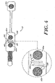
- the array 10 of electrodes 12 includes two temple electrodes 12c that allow for depth of anesthesia, burst suppression, ischemia monitor, and EEG recordings as well as EMG detection.
- the signals could be averaged together or the second channel could be used as a backup signal If the first channel signals are lost.
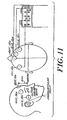
- the placement of the electrodes on a human head in such a two channel system is shown in Figure 11. Referring to Figure 10, In this configuration, conductor 16d is used to provide the signal from the second temple.
- the same array 10 described above in connection with Figure 1 is used in a different manner with the center of the main body 14 of the array 10 being placed over the temples and the electrode 12c on the satellite body 15 becomes the reference electrode.
- This configuration offers the advantage of keeping the cable away from the face of the patient.
- FIG 17 another array 10 of electrodes 12 is shown with a ground connection 12a, two frontal connections and two mastoid connections that can be used for depth of anesthesia, burst suppression, ischemia monitoring, and EEG recordings as well as EMG detection.
- the configuration shown in Figure 17 can be used to capture a hemisphere signal on each side of the head in order to produce bipolar readings.
- an array of electrodes will contain other passive devices such as but not limited to resistors, capacitors, or jumpers, for purposes of generating a code for self configuration.
- the array 10 of multiple electrodes 12 comprises of a flexible circuit with conductors that terminate on a tab connection that is double sided.
- the mating connector 124 has contacts 125 on top and bottom. This allows an increase in the density of the circuit while keeping the size of the connector to a small profile. It also allows for the separation of signals that are of digital nature from those of physioelectric nature. This reduces the amount of noise on the EEG signals
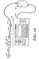
- the electrode array 10 is shown in use with an EEG monitor.
- the electrode array 10 is connected through connector via reusable connector 124 to a patient interface cable 142 which in tum is connected to a pigtall cable 144.
- the pigtail cable 144 is connected to a digital signal converter 146 which in turn is connected to monitor 150 through monitor interface cable 148.
- the digital signal converter may be embedded in the monitor thereby eliminating the need for cables 144, 148 or the electrode array 10 could also be connected to cable 144 thereby eliminating the need for cable 142.
Claims (10)
- Ensemble (10) d'une ou plusieurs électrodes (12) pour contrôler des signaux électriques physiologiques, ledit ensemble (10) comprenant un corps flexible et au moins une électrode (12) fixée audit corps flexible, caractérisé par le fait que ledit ensemble (10) comprend en outre un moyen pour stocker sur ledit corps flexible un code propre à l'ensemble (10) dans un connecteur relié audit ensemble d'électrodes (10).
- Ensemble (10) d'électrodes (12) pour contrôler des signaux électriques physiologiques, selon la revendication 1, dans lequel des conducteurs (16) sont positionnés sur ledit corps flexible pour transporter des signaux provenant desdites électrodes (12).
- Ensemble (10) d'électrodes (12) pour contrôler des signaux électriques physiologiques, selon la revendication 2, dans lequel ledit ensemble (10) comprend en outre un connecteur mâle non-conducteur (18) comprenant un dispositif de retenue (20) dans lequel lesdits conducteurs (16) sont insérés et bloqués.
- Ensemble (10) d'électrodes (12) pour contrôler des signaux électriques physiologiques, selon la revendication 3, dans lequel ledit connecteur mâle (18) comprend :un corps non-conducteur dans lequel lesdits conducteurs (16) sont insérés, ledit corps possédant une première extrémité et une seconde extrémité ;une charnière (47) positionnée entre ladite première extrémité et ladite seconde extrémité, autour de laquelle ladite seconde extrémité est apte à tourner pour être positionnée à proximité étroite de ladite première extrémité ;un mécanisme de blocage (48, 49) pour bloquer ladite seconde extrémité adjacente à ladite première extrémité.
- Ensemble (10) d'électrodes (12) pour contrôler des signaux électriques physiologiques, selon la revendication 1, comprenant en outre des dents non-conductrices (44) positionnées sous chaque électrode (12) pour séparer les couches de la peau d'un patient (32).
- Ensemble (10) d'électrodes (12) pour contrôler des signaux électriques physiologiques, selon la revendication 1, comprenant en outre un compartiment de soufflage (38) destiné à stocker un gel électrolytique (40) en dehors de tout contact avec le gel (40) de n'importe quelle autre électrode (12).
- Ensemble (10) d'électrodes (12) pour contrôler des signaux électriques physiologiques, selon la revendication 3, dans lequel ledit connecteur mâle (18) comprend en outre au moins deux rails (50) pour guider ledit connecteur (18) dans un connecteur réutilisable (124) dudit moniteur (150), lesdits rails (50) étant dimensionnés de manière unique pour une application particulière.
- Ensemble (10) d'électrodes (12) pour contrôler des signaux électriques physiologiques, selon la revendication 1, comprenant en outre une barrière de pont salin (46) pour empêcher le gel électrolytique (40) en contact avec l'une desdites électrodes (12) de venir en contact avec le gel électrolytique (40) en contact avec une seconde desdites électrodes (12), ladite barrière de pont salin (46) comprenant des puits à travers une mousse adhésive (39) fixée audit corps unitaire flexible.
- Ensemble (10) d'électrodes (12) selon l'une quelconque des revendications 1 à 8, dans lequel ledit ensemble (10) comprend en outre seulement trois électrodes (12) pour contrôler des signaux électriques physiologiques, un corps unitaire flexible ayant une partie principale (14), une partie satellite (15) et une extension flexible (17) située entre ladite partie principale (14) et ladite partie satellite (15) ; deux électrodes (12a, 12b) des trois électrodes (12) étant fixées de façon permanente à ladite partie principale (14) et une troisième électrode (12c) des trois électrodes (12) étant positionnée sur ladite partie satellite (15).
- Ensemble (10) d'électrodes (12) selon l'une quelconque des revendications 1 à 8, dans lequel ledit ensemble (10) comprend en outre seulement quatre électrodes (12) pour contrôler des signaux électriques physiologiques, un corps flexible ayant une partie principale (14), au moins une ou deux parties satellites (15) et une extension flexible (17) située entre ladite partie principale (14) et chacune desdites au moins une ou deux parties satellites (15) ;
au moins deux électrodes (12a, 12b) des quatre électrodes (12) étant positionnées sur ladite partie principale (14) et une électrode (12c) des quatre électrodes (12) étant positionnée sur chacune desdites parties satellites (15).
Applications Claiming Priority (3)
| Application Number | Priority Date | Filing Date | Title |
|---|---|---|---|
| US730638 | 1996-10-11 | ||
| US08/730,638 US6032064A (en) | 1996-10-11 | 1996-10-11 | Electrode array system for measuring electrophysiological signals |
| EP97911789A EP0951233B1 (fr) | 1996-10-11 | 1997-10-10 | Systeme d'ensemble d'electrodes permettant de mesurer des signaux electrophysiologiques |
Related Parent Applications (1)
| Application Number | Title | Priority Date | Filing Date |
|---|---|---|---|
| EP97911789A Division EP0951233B1 (fr) | 1996-10-11 | 1997-10-10 | Systeme d'ensemble d'electrodes permettant de mesurer des signaux electrophysiologiques |
Publications (2)
| Publication Number | Publication Date |
|---|---|
| EP1350462A1 EP1350462A1 (fr) | 2003-10-08 |
| EP1350462B1 true EP1350462B1 (fr) | 2005-12-28 |
Family
ID=24936170
Family Applications (2)
| Application Number | Title | Priority Date | Filing Date |
|---|---|---|---|
| EP03010436A Expired - Lifetime EP1350462B1 (fr) | 1996-10-11 | 1997-10-10 | Système d'ensemble d'élecctrodes permettant de mesurer des signaux électrophysiologiques |
| EP97911789A Expired - Lifetime EP0951233B1 (fr) | 1996-10-11 | 1997-10-10 | Systeme d'ensemble d'electrodes permettant de mesurer des signaux electrophysiologiques |
Family Applications After (1)
| Application Number | Title | Priority Date | Filing Date |
|---|---|---|---|
| EP97911789A Expired - Lifetime EP0951233B1 (fr) | 1996-10-11 | 1997-10-10 | Systeme d'ensemble d'electrodes permettant de mesurer des signaux electrophysiologiques |
Country Status (8)
| Country | Link |
|---|---|
| US (1) | US6032064A (fr) |
| EP (2) | EP1350462B1 (fr) |
| JP (3) | JP4582509B2 (fr) |
| AT (2) | ATE314004T1 (fr) |
| AU (1) | AU741021B2 (fr) |
| CA (1) | CA2268483C (fr) |
| DE (2) | DE69735021T2 (fr) |
| WO (1) | WO1998016152A2 (fr) |
Cited By (1)
| Publication number | Priority date | Publication date | Assignee | Title |
|---|---|---|---|---|
| US8115635B2 (en) | 2005-02-08 | 2012-02-14 | Abbott Diabetes Care Inc. | RF tag on test strips, test strip vials and boxes |
Families Citing this family (158)
| Publication number | Priority date | Publication date | Assignee | Title |
|---|---|---|---|---|
| US6032064A (en) * | 1996-10-11 | 2000-02-29 | Aspect Medical Systems, Inc. | Electrode array system for measuring electrophysiological signals |
| US6032072A (en) * | 1998-01-30 | 2000-02-29 | Aspect Medical Systems, Inc. | Method for enhancing and separating biopotential signals |
| US6898582B2 (en) | 1998-12-30 | 2005-05-24 | Algodyne, Ltd. | Method and apparatus for extracting low SNR transient signals from noise |
| US6385473B1 (en) * | 1999-04-15 | 2002-05-07 | Nexan Limited | Physiological sensor device |
| US6298255B1 (en) * | 1999-06-09 | 2001-10-02 | Aspect Medical Systems, Inc. | Smart electrophysiological sensor system with automatic authentication and validation and an interface for a smart electrophysiological sensor system |
| US6708049B1 (en) * | 1999-09-28 | 2004-03-16 | Nellcor Puritan Bennett Incorporated | Sensor with signature of data relating to sensor |
| US6549810B1 (en) | 1999-12-01 | 2003-04-15 | Vertis Neuroscience, Inc. | Percutaneous electrical therapy system with electrode depth control |
| US6556869B1 (en) | 1999-12-01 | 2003-04-29 | Vertis Neuroscience, Inc. | Electrode introducer for a percutaneous electrical therapy system |
| US6539264B1 (en) | 1999-12-01 | 2003-03-25 | Vertis Neuroscience, Inc. | Percutaneous electrical therapy system with sharp point protection |
| US6493592B1 (en) | 1999-12-01 | 2002-12-10 | Vertis Neuroscience, Inc. | Percutaneous electrical therapy system with electrode position maintenance |
| US6912424B2 (en) * | 1999-12-01 | 2005-06-28 | Meagan, Medical, Inc. | Apparatus and method for coupling therapeutic and/or monitoring equipment to a patient |
| US6904324B2 (en) * | 1999-12-01 | 2005-06-07 | Meagan Medical, Inc. | Method and apparatus for deploying a percutaneous probe |
| US6529776B1 (en) | 1999-12-01 | 2003-03-04 | Vertis Neuroscience, Inc. | Method and apparatus for repositioning a percutaneous probe |
| US6522927B1 (en) | 1999-12-01 | 2003-02-18 | Vertis Neuroscience, Inc. | Electrode assembly for a percutaneous electrical therapy system |
| US6560491B1 (en) | 1999-12-01 | 2003-05-06 | Vertis Neuroscience, Inc. | Percutaneous electrical therapy system providing electrode axial support |
| US7003336B2 (en) * | 2000-02-10 | 2006-02-21 | Medtronic Minimed, Inc. | Analyte sensor method of making the same |
| DE10015026C2 (de) * | 2000-03-25 | 2002-05-08 | Draeger Medical Ag | Anordnung und Verfahren zur Regelung eines numerischen Werts für die Patientenbeatmung |
| US6285904B1 (en) * | 2000-03-27 | 2001-09-04 | Sandia Corporation | Method and apparatus for determining fat content of tissue |
| WO2002000096A2 (fr) * | 2000-06-23 | 2002-01-03 | Physiometrix, Inc. | Reseau d'electrodes frontales servant a acquerir des signaux d'electroencephalogramme d'un patient |
| US6757558B2 (en) | 2000-07-06 | 2004-06-29 | Algodyne, Ltd. | Objective pain measurement system and method |
| US6564079B1 (en) * | 2000-07-27 | 2003-05-13 | Ckm Diagnostics, Inc. | Electrode array and skin attachment system for noninvasive nerve location and imaging device |
| US7118555B2 (en) * | 2000-09-21 | 2006-10-10 | Meagan Medical, Inc. | Method and apparatus for repositioning a percutaneous probe |
| WO2002030261A2 (fr) * | 2000-10-09 | 2002-04-18 | Brainz Instruments Limited | Ensemble de detection pour la surveillance du cerveau d'un bebe |
| US6671557B1 (en) | 2000-10-10 | 2003-12-30 | Meagan Medical, Inc. | System and method for providing percutaneous electrical therapy |
| US7011410B2 (en) | 2000-11-22 | 2006-03-14 | Eyetect, L.L.C. | Method and apparatus for monitoring eye tremor |
| US6567695B1 (en) * | 2000-11-24 | 2003-05-20 | Woodside Biomedical, Inc. | Electro-acupuncture device with stimulation electrode assembly |
| KR20040047754A (ko) * | 2001-06-13 | 2004-06-05 | 컴퓨메딕스 리미티드 | 의식 상태를 모니터링하기 위한 방법 및 장치 |
| US6728564B2 (en) * | 2001-07-03 | 2004-04-27 | Instrumentarium Corp. | Configurable sensor system for measuring biopotentials |
| US7286864B1 (en) | 2001-09-07 | 2007-10-23 | Orbital Research, Inc. | Dry physiological recording device |
| US6785569B2 (en) | 2001-09-07 | 2004-08-31 | Orbital Research | Dry physiological recording electrode |
| US6782283B2 (en) | 2001-09-07 | 2004-08-24 | Robert N. Schmidt | Dry penetrating recording device |
| US20040061232A1 (en) * | 2002-09-27 | 2004-04-01 | Medtronic Minimed, Inc. | Multilayer substrate |
| US8003513B2 (en) * | 2002-09-27 | 2011-08-23 | Medtronic Minimed, Inc. | Multilayer circuit devices and manufacturing methods using electroplated sacrificial structures |
| US8594764B2 (en) * | 2003-03-07 | 2013-11-26 | Jon Rice | Device and method for assessing the electrical potential of cells and method for manufacture of same |
| US7130673B2 (en) * | 2003-04-08 | 2006-10-31 | Instrumentarium Corp. | Method of positioning electrodes for central nervous system monitoring and sensing pain reactions of a patient |
| US6961603B2 (en) * | 2003-06-17 | 2005-11-01 | Instrumentarim Corp. | Unitary multi-electrode biopotential signal sensor and method for making same |
| US7731360B2 (en) * | 2003-11-07 | 2010-06-08 | Neuro Kinetics | Portable video oculography system |
| WO2005058145A2 (fr) * | 2003-12-17 | 2005-06-30 | The Regents Of The University Of Colorado, A Body Corporate | Dispositif et technique d'encephalographie electrique effractive active |
| US7212865B2 (en) * | 2004-05-25 | 2007-05-01 | Philip Cory | Nerve stimulator and method |
| CA3090413C (fr) | 2004-06-04 | 2023-10-10 | Abbott Diabetes Care Inc. | Surveillance du glucose et representations graphiques dans un systeme gestion de donnees |
| US20050280531A1 (en) * | 2004-06-18 | 2005-12-22 | Fadem Kalford C | Device and method for transmitting physiologic data |
| US8029441B2 (en) | 2006-02-28 | 2011-10-04 | Abbott Diabetes Care Inc. | Analyte sensor transmitter unit configuration for a data monitoring and management system |
| EP1850745B8 (fr) * | 2005-01-31 | 2020-04-01 | Koninklijke Philips N.V. | Electrode double |
| US20060236128A1 (en) * | 2005-04-04 | 2006-10-19 | Christian Christiansen | Method for authentication of electronic components |
| US8311622B2 (en) * | 2005-12-01 | 2012-11-13 | Neba Health LLC | Systems and methods for analyzing and assessing depression and other mood disorders using electroencephalographic (EEG) measurements |
| US7616980B2 (en) * | 2006-05-08 | 2009-11-10 | Tyco Healthcare Group Lp | Radial electrode array |
| CA2665121C (fr) * | 2006-09-16 | 2013-11-26 | Terence Gilhuly | Modelisation et commande de procedes non lineaires et hautement variables |
| US8109883B2 (en) * | 2006-09-28 | 2012-02-07 | Tyco Healthcare Group Lp | Cable monitoring apparatus |
| US20080091090A1 (en) * | 2006-10-12 | 2008-04-17 | Kenneth Shane Guillory | Self-contained surface physiological monitor with adhesive attachment |
| US20080091089A1 (en) * | 2006-10-12 | 2008-04-17 | Kenneth Shane Guillory | Single use, self-contained surface physiological monitor |
| US20080146958A1 (en) * | 2006-10-12 | 2008-06-19 | Kenneth Shane Guillory | Self-contained seizure monitor and method |
| US8238996B2 (en) * | 2006-12-05 | 2012-08-07 | Tyco Healthcare Group Lp | Electrode array |
| US8180425B2 (en) | 2006-12-05 | 2012-05-15 | Tyco Healthcare Group Lp | ECG lead wire organizer and dispenser |
| US8668651B2 (en) | 2006-12-05 | 2014-03-11 | Covidien Lp | ECG lead set and ECG adapter system |
| US20080199894A1 (en) | 2007-02-15 | 2008-08-21 | Abbott Diabetes Care, Inc. | Device and method for automatic data acquisition and/or detection |
| US8121857B2 (en) | 2007-02-15 | 2012-02-21 | Abbott Diabetes Care Inc. | Device and method for automatic data acquisition and/or detection |
| US7826882B2 (en) * | 2007-04-03 | 2010-11-02 | Tyco Electronics Corporation | Electrode lead set for measuring physiologic information |
| US20080249389A1 (en) * | 2007-04-03 | 2008-10-09 | Tyco Electronics Corporation | Electrode lead set for measuring physiologic information |
| US7996056B2 (en) * | 2007-06-15 | 2011-08-09 | The General Electric Company | Method and apparatus for acquiring physiological data |
| US20090088652A1 (en) * | 2007-09-28 | 2009-04-02 | Kathleen Tremblay | Physiological sensor placement and signal transmission device |
| CA2646037C (fr) | 2007-12-11 | 2017-11-28 | Tyco Healthcare Group Lp | Connecteur d'electrode pour ecg |
| US20090227857A1 (en) * | 2008-03-06 | 2009-09-10 | Chuck Rowe | Biomedical electrode |
| US8548558B2 (en) * | 2008-03-06 | 2013-10-01 | Covidien Lp | Electrode capable of attachment to a garment, system, and methods of manufacturing |
| US9655515B2 (en) * | 2008-04-08 | 2017-05-23 | Neuro Kinetics | Method of precision eye-tracking through use of iris edge based landmarks in eye geometry |
| WO2009134763A1 (fr) * | 2008-04-29 | 2009-11-05 | Board of Governors for Higher Education, State of Rhode Island and the Providence Plantations | Capteurs biomédicaux pouvant être utilisés sur des surfaces de contact non préparées |
| WO2009135200A2 (fr) | 2008-05-02 | 2009-11-05 | Aspect Medical Systems, Inc. | Dispositif pour préparer la peau et capteur de biopotentiel |
| US10398309B2 (en) | 2008-10-09 | 2019-09-03 | Neuro Kinetics, Inc. | Noninvasive rapid screening of mild traumatic brain injury using combination of subject's objective oculomotor, vestibular and reaction time analytic variables |
| US8585609B2 (en) * | 2008-10-09 | 2013-11-19 | Neuro Kinetics, Inc. | Quantitative, non-invasive, clinical diagnosis of traumatic brain injury using simulated distance visual stimulus device for neurologic testing |
| US9039631B2 (en) | 2008-10-09 | 2015-05-26 | Neuro Kinetics | Quantitative, non-invasive, clinical diagnosis of traumatic brain injury using VOG device for neurologic testing |
| US8868216B2 (en) * | 2008-11-21 | 2014-10-21 | Covidien Lp | Electrode garment |
| USD737979S1 (en) | 2008-12-09 | 2015-09-01 | Covidien Lp | ECG electrode connector |
| CZ302213B6 (cs) * | 2009-02-17 | 2010-12-22 | Západoceská@univerzita@v@Plzni | Zarízení@pro@sledování@procesu@vytvrzované@pryskyrice |
| US9408575B2 (en) | 2009-04-29 | 2016-08-09 | Bio-Signal Group Corp. | EEG kit |
| US7902851B2 (en) * | 2009-06-10 | 2011-03-08 | Medtronic, Inc. | Hermeticity testing |
| US8172760B2 (en) | 2009-06-18 | 2012-05-08 | Medtronic, Inc. | Medical device encapsulated within bonded dies |
| JP2011005177A (ja) * | 2009-06-29 | 2011-01-13 | Sony Corp | 生体信号測定用装具及び生体信号測定方法 |
| JP5589593B2 (ja) * | 2009-06-29 | 2014-09-17 | ソニー株式会社 | 生体信号測定用装具 |
| US9351659B2 (en) * | 2009-07-28 | 2016-05-31 | Altec, Inc. | Biomedical electrode configuration for suppressing movement artifact |
| AU2010282150B2 (en) * | 2009-08-14 | 2016-03-31 | David Burton | Anaesthesia and consciousness depth monitoring system |
| AU2010286595A1 (en) * | 2009-08-28 | 2012-02-23 | NEBA Health, LLC. | Systems and methods to identify a subgroup of ADHD at higher risk for complicating conditions |
| CN102686152A (zh) * | 2009-10-16 | 2012-09-19 | 飞机医疗有限公司 | 换能器安装件以及可佩带式监控器 |
| US8694080B2 (en) * | 2009-10-21 | 2014-04-08 | Covidien Lp | ECG lead system |
| CA2746944C (fr) | 2010-07-29 | 2018-09-25 | Tyco Healthcare Group Lp | Systeme adaptateur pour ecg et methode connexe |
| JP5710767B2 (ja) * | 2010-09-28 | 2015-04-30 | マシモ コーポレイション | オキシメータを含む意識深度モニタ |
| US8666505B2 (en) | 2010-10-26 | 2014-03-04 | Medtronic, Inc. | Wafer-scale package including power source |
| US8424388B2 (en) | 2011-01-28 | 2013-04-23 | Medtronic, Inc. | Implantable capacitive pressure sensor apparatus and methods regarding same |
| US10136845B2 (en) | 2011-02-28 | 2018-11-27 | Abbott Diabetes Care Inc. | Devices, systems, and methods associated with analyte monitoring devices and devices incorporating the same |
| US8577440B2 (en) | 2011-03-29 | 2013-11-05 | Covidien Lp | Method and system for positioning a sensor |
| DE102011101583B4 (de) * | 2011-05-12 | 2014-09-11 | Otto Bock Healthcare Gmbh | Elektrode zum transkutanen Übertragen elektrischer Signale und Verfahren zum Herstellen einer solchen |
| CN103687537B (zh) | 2011-07-22 | 2016-02-24 | 柯惠有限合伙公司 | Ecg电极连接器 |
| CN103006199B (zh) * | 2011-09-26 | 2016-09-28 | 三星电子株式会社 | 用于测量生物信号的设备和方法 |
| KR101941171B1 (ko) * | 2011-09-26 | 2019-01-23 | 삼성전자주식회사 | 생체신호를 측정하는 장치 및 방법 |
| US9220436B2 (en) | 2011-09-26 | 2015-12-29 | Covidien Lp | Technique for remanufacturing a BIS sensor |
| US8634901B2 (en) | 2011-09-30 | 2014-01-21 | Covidien Lp | ECG leadwire system with noise suppression and related methods |
| US8948685B2 (en) * | 2012-01-06 | 2015-02-03 | Blackberry Limited | Mobile wireless communications device using wired headset as an antenna and related methods |
| GB2499595A (en) * | 2012-02-21 | 2013-08-28 | James Roche | Infant EEG electrode system |
| US10188307B2 (en) | 2012-02-23 | 2019-01-29 | Bio-Signal Group Corp. | Shielded multi-channel EEG headset systems and methods |
| US8808179B1 (en) | 2012-08-06 | 2014-08-19 | James Z. Cinberg | Method and associated apparatus for detecting minor traumatic brain injury |
| US20140066741A1 (en) * | 2012-08-29 | 2014-03-06 | General Electric Company | Disposable ECG Leadwire Connector |
| US9510762B2 (en) * | 2012-09-04 | 2016-12-06 | Lkc Technologies, Inc. | Electrode arrays |
| US10182736B2 (en) | 2012-10-12 | 2019-01-22 | The Regents Of The University Of California | Configuration and spatial placement of frontal electrode sensors to detect physiological signals |
| WO2014057083A2 (fr) * | 2012-10-12 | 2014-04-17 | Delta, Dansk Elektronik, Lys Og Akustik | Dispositif de surveillance |
| FI126093B (fi) | 2012-11-12 | 2016-06-30 | Mega Elektroniikka Oy | Järjestely ja menetelmä elektrodimittausten suorittamiseksi |
| US9192313B1 (en) | 2013-03-14 | 2015-11-24 | Orbital Research Inc. | Dry physiological recording device and method of manufacturing |
| WO2014149548A1 (fr) | 2013-03-15 | 2014-09-25 | Covidien Lp | Connecteur d'électrode à élément conducteur |
| USD771818S1 (en) | 2013-03-15 | 2016-11-15 | Covidien Lp | ECG electrode connector |
| US9408546B2 (en) | 2013-03-15 | 2016-08-09 | Covidien Lp | Radiolucent ECG electrode system |
| CN103230271B (zh) * | 2013-05-07 | 2015-07-15 | 上海交通大学 | 一种可用于获取四肢表面肌电信号的可佩戴电极阵列 |
| US9737224B2 (en) | 2013-09-25 | 2017-08-22 | Bardy Diagnostics, Inc. | Event alerting through actigraphy embedded within electrocardiographic data |
| US9364155B2 (en) | 2013-09-25 | 2016-06-14 | Bardy Diagnostics, Inc. | Self-contained personal air flow sensing monitor |
| US10433748B2 (en) | 2013-09-25 | 2019-10-08 | Bardy Diagnostics, Inc. | Extended wear electrocardiography and physiological sensor monitor |
| US10165946B2 (en) | 2013-09-25 | 2019-01-01 | Bardy Diagnostics, Inc. | Computer-implemented system and method for providing a personal mobile device-triggered medical intervention |
| US10806360B2 (en) | 2013-09-25 | 2020-10-20 | Bardy Diagnostics, Inc. | Extended wear ambulatory electrocardiography and physiological sensor monitor |
| US10667711B1 (en) | 2013-09-25 | 2020-06-02 | Bardy Diagnostics, Inc. | Contact-activated extended wear electrocardiography and physiological sensor monitor recorder |
| US9408551B2 (en) | 2013-11-14 | 2016-08-09 | Bardy Diagnostics, Inc. | System and method for facilitating diagnosis of cardiac rhythm disorders with the aid of a digital computer |
| US9700227B2 (en) | 2013-09-25 | 2017-07-11 | Bardy Diagnostics, Inc. | Ambulatory electrocardiography monitoring patch optimized for capturing low amplitude cardiac action potential propagation |
| US10799137B2 (en) | 2013-09-25 | 2020-10-13 | Bardy Diagnostics, Inc. | System and method for facilitating a cardiac rhythm disorder diagnosis with the aid of a digital computer |
| US10888239B2 (en) | 2013-09-25 | 2021-01-12 | Bardy Diagnostics, Inc. | Remote interfacing electrocardiography patch |
| WO2015048194A1 (fr) | 2013-09-25 | 2015-04-02 | Bardy Diagnostics, Inc. | Moniteur personnel autonome de détection du débit d'air |
| US20190167139A1 (en) | 2017-12-05 | 2019-06-06 | Gust H. Bardy | Subcutaneous P-Wave Centric Insertable Cardiac Monitor For Long Term Electrocardiographic Monitoring |
| US10251576B2 (en) | 2013-09-25 | 2019-04-09 | Bardy Diagnostics, Inc. | System and method for ECG data classification for use in facilitating diagnosis of cardiac rhythm disorders with the aid of a digital computer |
| US9730593B2 (en) | 2013-09-25 | 2017-08-15 | Bardy Diagnostics, Inc. | Extended wear ambulatory electrocardiography and physiological sensor monitor |
| US9655537B2 (en) | 2013-09-25 | 2017-05-23 | Bardy Diagnostics, Inc. | Wearable electrocardiography and physiology monitoring ensemble |
| US9775536B2 (en) | 2013-09-25 | 2017-10-03 | Bardy Diagnostics, Inc. | Method for constructing a stress-pliant physiological electrode assembly |
| US10433751B2 (en) | 2013-09-25 | 2019-10-08 | Bardy Diagnostics, Inc. | System and method for facilitating a cardiac rhythm disorder diagnosis based on subcutaneous cardiac monitoring data |
| US10736531B2 (en) | 2013-09-25 | 2020-08-11 | Bardy Diagnostics, Inc. | Subcutaneous insertable cardiac monitor optimized for long term, low amplitude electrocardiographic data collection |
| US9433380B1 (en) | 2013-09-25 | 2016-09-06 | Bardy Diagnostics, Inc. | Extended wear electrocardiography patch |
| US9615763B2 (en) | 2013-09-25 | 2017-04-11 | Bardy Diagnostics, Inc. | Ambulatory electrocardiography monitor recorder optimized for capturing low amplitude cardiac action potential propagation |
| US10736529B2 (en) | 2013-09-25 | 2020-08-11 | Bardy Diagnostics, Inc. | Subcutaneous insertable electrocardiography monitor |
| US9655538B2 (en) | 2013-09-25 | 2017-05-23 | Bardy Diagnostics, Inc. | Self-authenticating electrocardiography monitoring circuit |
| US11723575B2 (en) | 2013-09-25 | 2023-08-15 | Bardy Diagnostics, Inc. | Electrocardiography patch |
| US9504423B1 (en) | 2015-10-05 | 2016-11-29 | Bardy Diagnostics, Inc. | Method for addressing medical conditions through a wearable health monitor with the aid of a digital computer |
| US9433367B2 (en) | 2013-09-25 | 2016-09-06 | Bardy Diagnostics, Inc. | Remote interfacing of extended wear electrocardiography and physiological sensor monitor |
| US9717433B2 (en) | 2013-09-25 | 2017-08-01 | Bardy Diagnostics, Inc. | Ambulatory electrocardiography monitoring patch optimized for capturing low amplitude cardiac action potential propagation |
| US10820801B2 (en) | 2013-09-25 | 2020-11-03 | Bardy Diagnostics, Inc. | Electrocardiography monitor configured for self-optimizing ECG data compression |
| US9408545B2 (en) | 2013-09-25 | 2016-08-09 | Bardy Diagnostics, Inc. | Method for efficiently encoding and compressing ECG data optimized for use in an ambulatory ECG monitor |
| US10624551B2 (en) | 2013-09-25 | 2020-04-21 | Bardy Diagnostics, Inc. | Insertable cardiac monitor for use in performing long term electrocardiographic monitoring |
| US11213237B2 (en) | 2013-09-25 | 2022-01-04 | Bardy Diagnostics, Inc. | System and method for secure cloud-based physiological data processing and delivery |
| US9619660B1 (en) | 2013-09-25 | 2017-04-11 | Bardy Diagnostics, Inc. | Computer-implemented system for secure physiological data collection and processing |
| US9345414B1 (en) | 2013-09-25 | 2016-05-24 | Bardy Diagnostics, Inc. | Method for providing dynamic gain over electrocardiographic data with the aid of a digital computer |
| US9717432B2 (en) * | 2013-09-25 | 2017-08-01 | Bardy Diagnostics, Inc. | Extended wear electrocardiography patch using interlaced wire electrodes |
| US10463269B2 (en) | 2013-09-25 | 2019-11-05 | Bardy Diagnostics, Inc. | System and method for machine-learning-based atrial fibrillation detection |
| EP3054848B1 (fr) | 2013-10-07 | 2019-09-25 | Masimo Corporation | Capsule d'oxymétrie régionale |
| AU353244S (en) * | 2013-10-11 | 2014-01-16 | Gi Therapies Pty Ltd | Electrical connector |
| US10111617B2 (en) | 2014-09-22 | 2018-10-30 | Covidien Lp | Systems and methods for EEG monitoring |
| WO2016057553A1 (fr) | 2014-10-07 | 2016-04-14 | Masimo Corporation | Capteurs physiologiques modulaires |
| US9955905B2 (en) * | 2015-02-16 | 2018-05-01 | NeuroSteer Ltd. | Systems and methods for brain activity interpretation |
| WO2017060560A1 (fr) | 2015-10-08 | 2017-04-13 | University Of Eastern Finland | Agencement pour conduire des mesures d'électrode |
| JP6629887B2 (ja) * | 2016-01-12 | 2020-01-15 | 国立大学法人大阪大学 | 生体信号計測装置 |
| KR102054558B1 (ko) * | 2016-10-28 | 2019-12-12 | 주식회사 인바디 | 마취 심도계 전극 |
| WO2018226809A1 (fr) | 2017-06-07 | 2018-12-13 | Covidien Lp | Systèmes et procédés de détection d'accidents vasculaires cérébraux |
| KR102353644B1 (ko) * | 2017-06-30 | 2022-01-21 | 주식회사 브레인유 | 마취심도 센서 |
| JP6709771B2 (ja) * | 2017-10-05 | 2020-06-17 | アトムメディカル株式会社 | 生体情報検出装置 |
| JP6649996B2 (ja) | 2018-06-26 | 2020-02-19 | アトムメディカル株式会社 | 子宮用止血バルーンユニット |
| US11096579B2 (en) | 2019-07-03 | 2021-08-24 | Bardy Diagnostics, Inc. | System and method for remote ECG data streaming in real-time |
| US11116451B2 (en) | 2019-07-03 | 2021-09-14 | Bardy Diagnostics, Inc. | Subcutaneous P-wave centric insertable cardiac monitor with energy harvesting capabilities |
| US11696681B2 (en) | 2019-07-03 | 2023-07-11 | Bardy Diagnostics Inc. | Configurable hardware platform for physiological monitoring of a living body |
| CN114469138B (zh) * | 2022-01-13 | 2024-04-19 | 博睿康医疗科技(上海)有限公司 | 基于时频域的脑电爆发抑制模式的检测方法、系统及介质 |
Family Cites Families (42)
| Publication number | Priority date | Publication date | Assignee | Title |
|---|---|---|---|---|
| US3490439A (en) * | 1965-07-30 | 1970-01-20 | Dale R Rolston | Electrode holder for use with an electroencephalograph |
| JPS5228789Y2 (fr) * | 1971-11-29 | 1977-06-30 | ||
| US3774592A (en) * | 1971-12-16 | 1973-11-27 | Xerox Corp | Method for providing an improved body electrode electrical connection |
| JPS552961Y2 (fr) * | 1974-03-25 | 1980-01-24 | ||
| US3999826A (en) * | 1975-06-30 | 1976-12-28 | General Motors Corporation | Connector for flexible printed circuit |
| US4072145A (en) * | 1976-07-19 | 1978-02-07 | Silva Jose R | Brain wave signal sensor headband assembly |
| JPS5730785Y2 (fr) * | 1976-09-13 | 1982-07-06 | ||
| US4082087A (en) * | 1977-02-07 | 1978-04-04 | Isis Medical Instruments | Body contact electrode structure for deriving electrical signals due to physiological activity |
| US4122843A (en) * | 1977-08-10 | 1978-10-31 | Electro-Technics, Inc. | Electrode system for a heart rate monitor |
| US4353372A (en) * | 1980-02-11 | 1982-10-12 | Bunker Ramo Corporation | Medical cable set and electrode therefor |
| GB2075194A (en) * | 1980-04-30 | 1981-11-11 | Sancha N S | Portable heart rate, pulse rate or temperature monitor |
| US4580557A (en) * | 1983-08-22 | 1986-04-08 | Laserscope | Surgical laser system with multiple output devices |
| US4595013A (en) * | 1984-08-17 | 1986-06-17 | Neurologics, Inc. | Electrode harness |
| JPS61133007U (fr) * | 1985-02-08 | 1986-08-19 | ||
| US4936306A (en) * | 1985-02-15 | 1990-06-26 | Doty James R | Device and method for monitoring evoked potentials and electroencephalograms |
| US4683892A (en) * | 1985-04-24 | 1987-08-04 | Johansson Nils E | Method and apparatus for conducting brain function diagnostic test |
| US4709702A (en) * | 1985-04-25 | 1987-12-01 | Westinghouse Electric Corp. | Electroencephalographic cap |
| US4640290A (en) * | 1985-04-25 | 1987-02-03 | Westinghouse Electric Corp. | Shielded, self-preparing electrode suitable for electroencephalographic mapping |
| US4638807A (en) * | 1985-08-27 | 1987-01-27 | Ryder International Corporation | Headband electrode system |
| US4706679A (en) * | 1986-01-27 | 1987-11-17 | Westinghouse Electric Corp. | Disposable monitor for an EEG head set |
| US4770180A (en) * | 1986-01-27 | 1988-09-13 | Westinghouse Electric Corp. | Electroencephalographic head set with a disposable monitor |
| US4967038A (en) * | 1986-12-16 | 1990-10-30 | Sam Techology Inc. | Dry electrode brain wave recording system |
| US5042481A (en) * | 1989-01-31 | 1991-08-27 | Sharp Kabushiki Kaisha | Body electrode holder |
| JPH0626241Y2 (ja) * | 1989-01-31 | 1994-07-20 | シャープ株式会社 | シート状生体用電極保持体 |
| JPH0741442Y2 (ja) * | 1989-01-31 | 1995-09-27 | シャープ株式会社 | 生体用電極保持体 |
| US4928696A (en) * | 1989-07-26 | 1990-05-29 | Mindcenter Corporation | Electrode-supporting headset |
| JPH0346303U (fr) * | 1989-09-14 | 1991-04-30 | ||
| AT397617B (de) * | 1990-04-20 | 1994-05-25 | Swarovski & Co | Flächenelektrode mit steckverbinder |
| JPH0483304U (fr) * | 1990-11-30 | 1992-07-20 | ||
| JPH0488906U (fr) * | 1991-01-08 | 1992-08-03 | ||
| US5341806A (en) * | 1991-04-18 | 1994-08-30 | Physio-Control Corporation | Multiple electrode strip |
| US5660177A (en) * | 1991-11-04 | 1997-08-26 | Biofield Corp. | D.C. biopotential sensing electrode assemblies for apparatus for disease, injury and bodily condition screening or sensing |
| US5327888A (en) * | 1992-06-05 | 1994-07-12 | Physiometrix, Inc. | Precordial electrode strip and apparatus and method using the same |
| US5265579A (en) * | 1992-09-21 | 1993-11-30 | Ferrari R Keith | X-ray transparent monitoring electrode and method for making |
| US5305746A (en) * | 1992-09-29 | 1994-04-26 | Aspect Medical Systems, Inc. | Disposable, pre-gelled, self-prepping electrode |
| JPH07108039A (ja) * | 1993-10-14 | 1995-04-25 | Hitachi Ltd | 身体情報検出装置 |
| JP2603317Y2 (ja) * | 1993-12-24 | 2000-03-06 | 矢崎総業株式会社 | フレキシブル基板接続用コネクタ |
| FR2720947B1 (fr) * | 1994-06-09 | 1996-08-09 | Odam Off Distri App Medicaux | Appareil défibrillateur muni d'une pluralité d'ensembles connecteur/électrodes de types différents. |
| IL115524A (en) * | 1994-10-17 | 2001-07-24 | Biofield Corp | D.c. biopotential sensing electrode and electroconductive medium for use therein |
| US5772591A (en) * | 1995-06-06 | 1998-06-30 | Patient Comfort, Inc. | Electrode assembly for signaling a monitor |
| US5813404A (en) * | 1995-10-20 | 1998-09-29 | Aspect Medical Systems, Inc. | Electrode connector system |
| US6032064A (en) * | 1996-10-11 | 2000-02-29 | Aspect Medical Systems, Inc. | Electrode array system for measuring electrophysiological signals |
-
1996
- 1996-10-11 US US08/730,638 patent/US6032064A/en not_active Expired - Lifetime
-
1997
- 1997-10-10 WO PCT/US1997/018833 patent/WO1998016152A2/fr active IP Right Grant
- 1997-10-10 AT AT03010436T patent/ATE314004T1/de active
- 1997-10-10 EP EP03010436A patent/EP1350462B1/fr not_active Expired - Lifetime
- 1997-10-10 AU AU49082/97A patent/AU741021B2/en not_active Ceased
- 1997-10-10 DE DE69735021T patent/DE69735021T2/de not_active Expired - Lifetime
- 1997-10-10 AT AT97911789T patent/ATE290816T1/de active
- 1997-10-10 DE DE69732790T patent/DE69732790T2/de not_active Expired - Lifetime
- 1997-10-10 JP JP51862698A patent/JP4582509B2/ja not_active Expired - Fee Related
- 1997-10-10 EP EP97911789A patent/EP0951233B1/fr not_active Expired - Lifetime
- 1997-10-10 CA CA002268483A patent/CA2268483C/fr not_active Expired - Fee Related
-
2007
- 2007-07-18 JP JP2007186504A patent/JP4496504B2/ja not_active Expired - Fee Related
-
2009
- 2009-10-16 JP JP2009239118A patent/JP2010046502A/ja active Pending
Cited By (5)
| Publication number | Priority date | Publication date | Assignee | Title |
|---|---|---|---|---|
| US8115635B2 (en) | 2005-02-08 | 2012-02-14 | Abbott Diabetes Care Inc. | RF tag on test strips, test strip vials and boxes |
| US8223021B2 (en) | 2005-02-08 | 2012-07-17 | Abbott Diabetes Care Inc. | RF tag on test strips, test strip vials and boxes |
| US8358210B2 (en) | 2005-02-08 | 2013-01-22 | Abbott Diabetes Care Inc. | RF tag on test strips, test strip vials and boxes |
| US8390455B2 (en) | 2005-02-08 | 2013-03-05 | Abbott Diabetes Care Inc. | RF tag on test strips, test strip vials and boxes |
| US8542122B2 (en) | 2005-02-08 | 2013-09-24 | Abbott Diabetes Care Inc. | Glucose measurement device and methods using RFID |
Also Published As
| Publication number | Publication date |
|---|---|
| JP2001502217A (ja) | 2001-02-20 |
| DE69732790D1 (de) | 2005-04-21 |
| JP4582509B2 (ja) | 2010-11-17 |
| JP2010046502A (ja) | 2010-03-04 |
| WO1998016152A9 (fr) | 2001-06-07 |
| EP0951233B1 (fr) | 2005-03-16 |
| WO1998016152A3 (fr) | 1998-06-25 |
| EP1350462A1 (fr) | 2003-10-08 |
| US6032064A (en) | 2000-02-29 |
| DE69732790T2 (de) | 2006-04-06 |
| AU741021B2 (en) | 2001-11-22 |
| DE69735021D1 (de) | 2006-02-02 |
| EP0951233A2 (fr) | 1999-10-27 |
| DE69735021T2 (de) | 2006-08-31 |
| CA2268483C (fr) | 2007-01-30 |
| AU4908297A (en) | 1998-05-11 |
| CA2268483A1 (fr) | 1998-04-23 |
| ATE290816T1 (de) | 2005-04-15 |
| ATE314004T1 (de) | 2006-01-15 |
| JP2007307398A (ja) | 2007-11-29 |
| JP4496504B2 (ja) | 2010-07-07 |
| WO1998016152A2 (fr) | 1998-04-23 |
Similar Documents
| Publication | Publication Date | Title |
|---|---|---|
| EP1350462B1 (fr) | Système d'ensemble d'élecctrodes permettant de mesurer des signaux électrophysiologiques | |
| US6654626B2 (en) | Electrode array system for measuring electrophysiological signals | |
| EP1054621B1 (fr) | Dispositif universel de positionnement d'un capteur d'electrocardiogramme et procede associe | |
| US6751493B2 (en) | Universal electrocardiogram sensor positioning mask with repositionable sensors and method for employing same | |
| US9770184B2 (en) | Arrangement and method for carrying out electrode measurements | |
| US5772591A (en) | Electrode assembly for signaling a monitor | |
| US9693701B2 (en) | Electrode connector design to aid in correct placement | |
| US6553246B1 (en) | Universal electrocardiogram sensor positioning device and method for four sizes including extra large | |
| EP1488740B1 (fr) | Détecteur unitaire de potentiels biologiques composé de plusieurs électrodes, et méthode de fabrication correspondante | |
| US20040210149A1 (en) | Right side universal electrocardiogram sensor positioning mask and method | |
| EP0199213A2 (fr) | Electrode blindée préconditionnée destinée à la présentation bi-dimensionnelle d'électro-encéphalogrammes | |
| AU779475B2 (en) | Electrode array system for measuring electrophysiological signals | |
| MXPA00007874A (en) | A universal electrocardiogram sensor positioning device and method |
Legal Events
| Date | Code | Title | Description |
|---|---|---|---|
| PUAI | Public reference made under article 153(3) epc to a published international application that has entered the european phase |
Free format text: ORIGINAL CODE: 0009012 |
|
| AC | Divisional application: reference to earlier application |
Ref document number: 0951233 Country of ref document: EP Kind code of ref document: P |
|
| AK | Designated contracting states |
Kind code of ref document: A1 Designated state(s): AT BE CH DE FR GB LI |
|
| RIN1 | Information on inventor provided before grant (corrected) |
Inventor name: FENDROCK, CHARLES Inventor name: MCDANIEL, TERRIE L. Inventor name: CORDERO, RAFAEL M. Inventor name: DEVLIN, PHILIP H. Inventor name: SHAMBROOM, JOHN R. Inventor name: CHAMOUN, NASSIB B. |
|
| 17P | Request for examination filed |
Effective date: 20040325 |
|
| 17Q | First examination report despatched |
Effective date: 20040420 |
|
| AKX | Designation fees paid |
Designated state(s): AT BE CH DE FR GB LI |
|
| GRAP | Despatch of communication of intention to grant a patent |
Free format text: ORIGINAL CODE: EPIDOSNIGR1 |
|
| GRAS | Grant fee paid |
Free format text: ORIGINAL CODE: EPIDOSNIGR3 |
|
| GRAA | (expected) grant |
Free format text: ORIGINAL CODE: 0009210 |
|
| AC | Divisional application: reference to earlier application |
Ref document number: 0951233 Country of ref document: EP Kind code of ref document: P |
|
| AK | Designated contracting states |
Kind code of ref document: B1 Designated state(s): AT BE CH DE FR GB LI |
|
| REG | Reference to a national code |
Ref country code: GB Ref legal event code: FG4D |
|
| REG | Reference to a national code |
Ref country code: CH Ref legal event code: EP |
|
| REF | Corresponds to: |
Ref document number: 69735021 Country of ref document: DE Date of ref document: 20060202 Kind code of ref document: P |
|
| REG | Reference to a national code |
Ref country code: CH Ref legal event code: NV Representative=s name: TROESCH SCHEIDEGGER WERNER AG |
|
| ET | Fr: translation filed | ||
| PLBE | No opposition filed within time limit |
Free format text: ORIGINAL CODE: 0009261 |
|
| STAA | Information on the status of an ep patent application or granted ep patent |
Free format text: STATUS: NO OPPOSITION FILED WITHIN TIME LIMIT |
|
| 26N | No opposition filed |
Effective date: 20060929 |
|
| PGFP | Annual fee paid to national office [announced via postgrant information from national office to epo] |
Ref country code: AT Payment date: 20100921 Year of fee payment: 14 |
|
| PGFP | Annual fee paid to national office [announced via postgrant information from national office to epo] |
Ref country code: CH Payment date: 20101025 Year of fee payment: 14 |
|
| PGFP | Annual fee paid to national office [announced via postgrant information from national office to epo] |
Ref country code: BE Payment date: 20101026 Year of fee payment: 14 |
|
| BERE | Be: lapsed |
Owner name: *ASPECT MEDICAL SYSTEMS INC. Effective date: 20111031 |
|
| REG | Reference to a national code |
Ref country code: CH Ref legal event code: PL |
|
| PG25 | Lapsed in a contracting state [announced via postgrant information from national office to epo] |
Ref country code: BE Free format text: LAPSE BECAUSE OF NON-PAYMENT OF DUE FEES Effective date: 20111031 Ref country code: LI Free format text: LAPSE BECAUSE OF NON-PAYMENT OF DUE FEES Effective date: 20111031 Ref country code: CH Free format text: LAPSE BECAUSE OF NON-PAYMENT OF DUE FEES Effective date: 20111031 |
|
| REG | Reference to a national code |
Ref country code: AT Ref legal event code: MM01 Ref document number: 314004 Country of ref document: AT Kind code of ref document: T Effective date: 20111010 |
|
| PG25 | Lapsed in a contracting state [announced via postgrant information from national office to epo] |
Ref country code: AT Free format text: LAPSE BECAUSE OF NON-PAYMENT OF DUE FEES Effective date: 20111010 |
|
| REG | Reference to a national code |
Ref country code: FR Ref legal event code: PLFP Year of fee payment: 19 |
|
| PGFP | Annual fee paid to national office [announced via postgrant information from national office to epo] |
Ref country code: GB Payment date: 20150924 Year of fee payment: 19 |
|
| PGFP | Annual fee paid to national office [announced via postgrant information from national office to epo] |
Ref country code: FR Payment date: 20150925 Year of fee payment: 19 |
|
| PGFP | Annual fee paid to national office [announced via postgrant information from national office to epo] |
Ref country code: DE Payment date: 20150922 Year of fee payment: 19 |
|
| REG | Reference to a national code |
Ref country code: DE Ref legal event code: R119 Ref document number: 69735021 Country of ref document: DE |
|
| GBPC | Gb: european patent ceased through non-payment of renewal fee |
Effective date: 20161010 |
|
| REG | Reference to a national code |
Ref country code: FR Ref legal event code: ST Effective date: 20170630 |
|
| PG25 | Lapsed in a contracting state [announced via postgrant information from national office to epo] |
Ref country code: GB Free format text: LAPSE BECAUSE OF NON-PAYMENT OF DUE FEES Effective date: 20161010 Ref country code: FR Free format text: LAPSE BECAUSE OF NON-PAYMENT OF DUE FEES Effective date: 20161102 Ref country code: DE Free format text: LAPSE BECAUSE OF NON-PAYMENT OF DUE FEES Effective date: 20170503 |