EP1348861A2 - Heizflansch, insbesondere zum Vorwärmen von Luft in einer Ansaugleitung einer Brennkraftmaschine - Google Patents
Heizflansch, insbesondere zum Vorwärmen von Luft in einer Ansaugleitung einer Brennkraftmaschine Download PDFInfo
- Publication number
- EP1348861A2 EP1348861A2 EP03004915A EP03004915A EP1348861A2 EP 1348861 A2 EP1348861 A2 EP 1348861A2 EP 03004915 A EP03004915 A EP 03004915A EP 03004915 A EP03004915 A EP 03004915A EP 1348861 A2 EP1348861 A2 EP 1348861A2
- Authority
- EP
- European Patent Office
- Prior art keywords
- heating
- flange according
- heating element
- heating flange
- air
- Prior art date
- Legal status (The legal status is an assumption and is not a legal conclusion. Google has not performed a legal analysis and makes no representation as to the accuracy of the status listed.)
- Granted
Links
Images


Classifications
-
- F—MECHANICAL ENGINEERING; LIGHTING; HEATING; WEAPONS; BLASTING
- F02—COMBUSTION ENGINES; HOT-GAS OR COMBUSTION-PRODUCT ENGINE PLANTS
- F02M—SUPPLYING COMBUSTION ENGINES IN GENERAL WITH COMBUSTIBLE MIXTURES OR CONSTITUENTS THEREOF
- F02M31/00—Apparatus for thermally treating combustion-air, fuel, or fuel-air mixture
- F02M31/02—Apparatus for thermally treating combustion-air, fuel, or fuel-air mixture for heating
- F02M31/12—Apparatus for thermally treating combustion-air, fuel, or fuel-air mixture for heating electrically
- F02M31/13—Combustion air
-
- Y—GENERAL TAGGING OF NEW TECHNOLOGICAL DEVELOPMENTS; GENERAL TAGGING OF CROSS-SECTIONAL TECHNOLOGIES SPANNING OVER SEVERAL SECTIONS OF THE IPC; TECHNICAL SUBJECTS COVERED BY FORMER USPC CROSS-REFERENCE ART COLLECTIONS [XRACs] AND DIGESTS
- Y02—TECHNOLOGIES OR APPLICATIONS FOR MITIGATION OR ADAPTATION AGAINST CLIMATE CHANGE
- Y02T—CLIMATE CHANGE MITIGATION TECHNOLOGIES RELATED TO TRANSPORTATION
- Y02T10/00—Road transport of goods or passengers
- Y02T10/10—Internal combustion engine [ICE] based vehicles
- Y02T10/12—Improving ICE efficiencies
Definitions
- the present invention relates to a heating flange, in particular for preheating of air in an intake line leading to an internal combustion engine the preamble of claim 1.
- the invention is based on the knowledge that a particularly good heat transfer between the heating element and the air to be preheated and a particularly robust and vibration-proof design of a heating flange can be achieved in that the Base body has a bracket with a substantially U-shaped cross section and the heating element has at least one essentially U-shaped meander loop comprises, which is firmly connected to the bracket at its base.
- the heating element is mechanically optimally protected on the one hand and is nevertheless in the largest possible area of its surface flows around the air to be heated. Due to this robust construction, the heating element is against the strong ones Engine vibrations resistant.
- Another advantage of the heating flange according to the invention is its simple and therefore inexpensive assembly due to less electrical and mechanical interfaces.
- the heating element is opposite the holding bracket electrically isolated at the base. In this way it is possible to use the bracket to a potential other than the heating element, for example to ground.
- a particularly inexpensive and effective way of such electrical insulation to realize is between the heating element and the base of the bracket an essentially rectangular plate made of an electrically insulating material, preferably to arrange mica, pressed mica or ceramic.
- an electrically insulating material preferably to arrange mica, pressed mica or ceramic.
- the material micanite offers the advantage of high dielectric strength (greater than 20 kV / mm), a permissible operating temperature of 600 ° C to 900 ° C, very low water absorption capacity (less than 1%) as well as good thermal conductivity.
- this material can be special easily get into the desired shape.
- Ferritic iron-chromium-aluminum alloys are a frequently used material for heating elements
- the Kanthal D® alloy a registered trademark from Kanthal AB, has for example a temperature stability up to 1300 ° C and is used for heating tasks both in the household sector and for industrial applications frequently used.
- the base body of the heating flange also a cover, through which the heating flange can be connected to the suction line, on.
- This enables a particularly simple assembly of the heating flange in the suction line can be achieved.
- the sealing of this cover against the suction line can, for example, have a flat seal or double O-rings attached to the Lids are arranged.
- the holding bracket with the lid electrically connected.
- the bracket like the lid, on Ground are placed and thus does not act as an antenna for the radiation of any electromagnetic Faults caused by the control of the heating elements become.
- the retaining bracket is electrical opposite the cover isolated. This has the advantage that between the bracket and the heating element no electrical insulation layer is required anymore and therefore the production can be done faster and with less material.
- the material of the U-shaped meander loop of the heating element usually has one different temperature coefficients than the material from which the bracket is made is. In addition, significantly higher temperatures are also on the heating element reached.
- the brackets are able to compare the bracket and heating element against each other the U-shaped meandering loop of the heating element in the free-standing, from the air flow surrounding area angled at least once. In this way it becomes resilient Storage of the heating element in the bracket causes, so that the heating element too is securely fixed in the event of violent vibrations and is deformed when exposed to heat is possible in a defined direction.
- the heating flange two heating elements, which in the direction transverse to the U-shaped cross section of the Bracket are arranged offset from each other. These two heating elements offer the advantage of increased heating power and a larger surface for heating the air flowing through.
- the Leg of the meandering loops of the two heating elements in opposite directions Be angled towards.
- the bracket on its flanks Openings for the inflow of the air to be heated transversely to the opening of the U-shaped Have cross-section.
- the heating flange has a switching device to switch the electrical power on and off on the heating element.
- a switching device can provide the electrical power to the heating element as required can be supplied and it can for example by defined switching on and off Pulse width modulation to regulate the heating power supply can be realized.
- this embodiment offers the advantage that Semiconductor component wear-free and safely switches that much higher switching frequencies can be realized and the size of the entire switching device can be greatly miniaturized compared to arrangements with relays.
- the power supply to the two heating elements can be offset in time occur that electromagnetic interference caused by the on and off cycles of the heating elements are caused to cancel each other out over time. Because the Interference energy stored in the line inductance proportional to the flowing current the electromagnetic interference is reduced accordingly by dividing the currents.
- this solution offers the advantage that the heating process is not more just controlled, but regulated and thus particularly energy-saving and efficient Way can be done.
- a temperature sensor can also to protect the electronics from overheating.
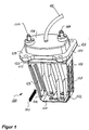
- FIG. 1 shows a perspective view of a heating flange according to the invention according to a first advantageous embodiment.
- the heating flange 100 has one Base body 101, on a suction line leading to an internal combustion engine can be mounted that the two heating elements 102 and 104 in the to Immerse warming airflow.
- the heating elements 102, 104 are flowing through electric current heats up and heats up the air around it.
- Each of the two heating elements 102, 104 is switched on in the embodiment shown an essentially U-shaped meander loop is formed.
- Such meander heating elements are particularly well suited for heating gaseous media because of the direct Contact with the heating conductor ensures good heat transfer.
- the two Heating elements 102, 104 are mechanically stabilized by a bracket 106.
- the heating elements 102, 104 with the base of the essentially U-shaped bracket 106 connected via rivet connections. Beyond that each heating element 102, 104 is connected to the voltage supply.
- a cover 108 which can preferably be made of plastic, is used to seal one corresponding opening in the intake line.
- In the lid 108 are also the Connection cables for the power supply and control electronics integrated.
- a bolt for positive voltage 114 and a bolt for the ground connection are led to the outside 116 and the connection cable 118 for the control.
- the heating elements 102, 104 both in the area of the carrying element 109 and in the Area of the base of the bracket 106 are fixed mechanically rigid, must be guaranteed be that with different thermal expansion of the heating elements 102, 104 compared to the bracket 106 a defined change in position of the heating elements 102, 104 takes place.
- the legs of the U-shaped meandering loops the heating elements 102, 104 are angled such that kinks 120 are formed, for a directed, predetermined change in position when the length of the legs increases provides. In this way it can be ensured that the legs of the meandering loops the heating elements to move towards each other or with the bracket 106 in Contact and in extreme cases cause an electrical short circuit.
- the main flow direction of the air is transverse to the U-shaped cross section of the bracket 106, as indicated by arrow 122. However, at the Legs of the bracket 106 openings 124 are provided, which also flow allow the air to be heated transversely to the main flow direction 122.
- the embodiment is the holding bracket 106 with the aluminum block 126 of the cover 108 conductively connected and grounded. The insulation to the heating elements 102, 104 takes place via the insulating plate 112.
- FIG. 1 Different views of the heating flange 100 according to the embodiment shown in FIG. 1 are shown in Figures 2 to 4.
- FIG. 5 shows a perspective illustration of a second advantageous embodiment, in which each heating element 102, 104 consists of two essentially U-shaped meandering loops consists.
- each heating element 102, 104 is immersed a total of four heat-releasing legs in the air flow. This one too Embodiment, it is useful to bend 120 for the defined deflection in thermal To provide expansion.
- the two heating elements 102, 104 are in a direction transverse to the U-shaped bracket 106 seen in succession and also parallel to the U-shaped cross section of the bracket 106 is arranged offset from each other. That way the largest possible surface area of the two heating elements 102, 104 from the current of the ones to be heated Be flushed with air. Isolation also takes place in this embodiment of the heating elements 102, 104 opposite the base of the holding bracket 106 and opposite the aluminum block 126 of the lid 108 over mica sheets 110 and 112. Both the mechanical fixation of the heating elements 102, 104, as well as the fastening to the insulation plate 110 at the base of the holding bracket 106 takes place via rivets 130.
- FIGS. 6 to 8 show different views of the heating flange 100 according to the in FIG Figure 5 embodiment shown.
- FIG. 9 is a perspective view of a heating flange 100 according to a third advantageous embodiment shown.
- the bracket is 106 is not conductive with the aluminum block as in the previously shown embodiments 126 connected, but electrically isolated from it by an insulation 112.
- the bracket 106 in this embodiment is at the base of its U-shaped cross section no longer electrically compared to the current-carrying heating elements 102, 104 must be insulated, it suffices for mechanically fixing the heating elements 102, 104 to provide the bracket 106 welds 132.
- This allows the manufacture be further simplified and cheaper.
- 9 corresponds to that of FIG. 1 Embodiment with only one meander loop per heating element 102, 104 shows, this embodiment can of course also with heating elements more than one meander loop can be used. In any case, both Rivets 130 and the insulation 110 are eliminated.
- FIG. 10 shows an example of a typical time profile of the heating power when starting of a diesel engine.
- the intake air is preheated with 100% heating output.
- By controlled intermittent shutdown of the heating power supply can be a simple Pulse width modulation can be achieved and after starting the air can still one predetermined period of time with lower heating output (for example 25% to 50%) be warmed up.
- This is e.g. B. useful if the outside temperature is very low and takes place in the example shown over a period of 20 seconds after switching on the heating.
- the maximum electrical heating output is in the range of approx. 10 kW. This high output means that the heating is particularly rapid of the intake air before starting.
- FIG 11 is a circuit diagram of the electronic control for a heating flange with two heating elements shown.
- the control electronics include a microcontroller that overloads the Prevents heating circuits, monitors their function and sends an alarm signal in the event of faults. Furthermore, the electronics are able to withstand permanent overvoltages in the Switch on the on-board electrical system in a controlled manner to electrically load the on-board electrical system and thus reduce the overvoltage.
- An optional temperature detection can be done via the temperature sensor 146 and on the basis of this information regulated intake air preheating can be performed by the microcontroller 144.
- a corresponding one can also be used single MOS field effect transistor can be used.
- Figure 12 shows the timing of the control signals for the two heating elements and resulting time course of load switching. So the two heating elements so that the heating element 2 (see curve 150) is then switched off when the heating element 1 (corresponding to curve 148) is straight has reached half of its "ON" phase. The load is switched on exactly when both heating elements are switched on (curve 152).
- Such a timed control of the two heating elements is e.g. B. advantageous if you by the Wants to reduce heating elements caused electromagnetic interference.
- an optical sensor can also be used, which detects infrared light. With this you could glow of the heating elements and regulate accordingly. So that would be a maximum Power supply possible, which would be adapted to the respective air flow without the Air flow must be determined elaborately. It is also a safe mode of operation possible if the airflow fails.
Landscapes
- Engineering & Computer Science (AREA)
- Chemical & Material Sciences (AREA)
- Combustion & Propulsion (AREA)
- Mechanical Engineering (AREA)
- General Engineering & Computer Science (AREA)
- Air-Conditioning For Vehicles (AREA)
- Resistance Heating (AREA)
- Lubrication Details And Ventilation Of Internal Combustion Engines (AREA)
- Exhaust Gas After Treatment (AREA)
Abstract
Description
- Sicherheitsabschaltung bei Erreichen der Maximaltemperatur bzw. maximalen Einschaltdauer,
- Überwachung der Halbleiterschaltelemente,
- Auslösen von Sicherheitsabschalteinrichtungen,
- Ermitteln des fließenden Stromes, dadurch Erkennen von Übergangswiderständen,
- Diagnosefunktionen,
- Verringern der elektromagnetischen Abstrahlung durch entsprechende Ansteueralgorithmen.
- Figur 1
- eine perspektivische Darstellung eines Heizflansches gemäß einer ersten vorteilhaften Ausführungsform;
- Figur 2
- eine Seitenansicht des Heizflansches aus Figur 1;
- Figur 3
- eine um 90° gedrehte Seitenansicht des Heizflansches aus Figur 2;
- Figur 4
- eine Ansicht von oben auf den Heizflansch aus Figur 1;
- Figur 5
- eine perspektivische Darstellung eines Heizflansches gemäß einer zweiten vorteilhaften Ausführungsform;
- Figur 6
- eine Seitenansicht des Heizflansches aus Figur 5;
- Figur 7
- eine um 90° gedrehte Seitenansicht des Heizflansches aus Figur 6;
- Figur 8
- eine Ansicht von oben auf den Heizflansch aus Figur 5;
- Figur 9
- eine perspektivische Ansicht eines Heizflansches gemäß einer dritten vorteilhaften Ausführungsform;
- Figur 10
- ein Zeitdiagramm der in den Heizflansch eingespeisten elektrischen Leistung;
- Figur 11
- ein Schaltbild eines elektrischen Schalteinrichtung zum Ansteuern zweier Heizelemente;
- Figur 12
- ein Zustandsdiagramm der Ansteuerung der beiden Heizelemente sowie der gesamten eingespeisten Leistung.
Claims (19)
- Heizflansch, insbesondere zum Vorwärmen von Luft in einer zu einer Brennkraftmaschine führenden Ansaugleitung, wobei der Heizflansch (100) mindestens ein Heizelement (102, 104) zur Erwärmung der vorbeiströmenden Luft sowie einen Grundkörper (101) zur mechanischen Halterung und elektrischen Kontaktierung des Heizelements (102, 104) aufweist,
dadurch gekennzeichnet, dass der Grundkörper einen Haltebügel (106) mit im Wesentlichen U-förmigem Querschnitt aufweist und das Heizelement (102, 104) mindestens eine im Wesentlichen U-förmig ausgestaltete Mäanderschleife umfasst, die mit dem Haltebügel (106) an dessen Basis fest verbunden ist. - Heizflansch nach Anspruch 1, dadurch gekennzeichnet, dass das Heizelement (102, 104) gegenüber dem Haltebügel (106) an dessen Basis elektrisch isoliert ist.
- Heizflansch nach Anspruch 2, dadurch gekennzeichnet, dass zwischen dem Heizelement (102, 104) und der Basis des Haltebügels (106) eine im Wesentlichen rechteckige Platte (110) aus einem elektrisch isolierenden Material, vorzugsweise Glimmer, Pressglimmer oder Keramik, angeordnet ist.
- Heizflansch nach einem der Ansprüche 1 bis 3, dadurch gekennzeichnet, dass das Heizelement (102, 104) mit dem Haltebügel (106) an dessen Basis vernietet ist.
- Heizflansch nach einem der Ansprüche 1 bis 3, dadurch gekennzeichnet, dass das Heizelement (102, 104) mit dem Haltebügel (106) an dessen Basis verschweißt ist.
- Heizflansch nach einem der Ansprüche 1 bis 5, dadurch gekennzeichnet, dass das Heizelement (102, 104) aus einer ferritischen Eisen-Chrom-Aluminium-Legierung, vorzugsweise Kanthal D, herstellbar ist.
- Heizflansch nach einem der Ansprüche 1 bis 6, dadurch gekennzeichnet, dass der Grundkörper (101) des Heizflansches (100) weiterhin einen Deckel (108), über den der Heizflansch (100) mit der Ansaugleitung verbindbar ist, aufweist.
- Heizflansch nach Anspruch 7, dadurch gekennzeichnet, dass der Haltebügel (106) mit dem Deckel (108) elektrisch leitend verbunden ist.
- Heizflansch nach Anspruch 7, dadurch gekennzeichnet, dass der Haltebügel (106) gegenüber dem Deckel (108) elektrisch isoliert ist.
- Heizflansch nach einem der Ansprüche 1 bis 9, dadurch gekennzeichnet, dass die Schenkel der U-förmigen Mäanderschleife des Heizelements (102, 104) in dem freistehenden, vom Luftstrom umgebenen Bereich mindestens einmal abgewinkelt sind.
- Heizflansch nach einem der Ansprüche 1 bis 10, dadurch gekennzeichnet, dass der Heizflansch (100) ein erstes (102) und ein zweites Heizelement (104) aufweist, die in einer Richtung quer zu dem U-förmigen Querschnitt des Haltebügels (106) gegeneinander versetzt angeordnet sind.
- Heizflansch nach Anspruch 11, dadurch gekennzeichnet, dass die Schenkel der Mäanderschleife des ersten Heizelements (102) in seinen freistehenden, vom Luftstrom umgebenen Bereichen in entgegengesetzter Richtung abgewinkelt sind wie die Schenkel der Mäanderschleife des zweiten Heizelements (104).
- Heizflansch nach einem der Ansprüche 1 bis 12, dadurch gekennzeichnet, dass der Haltebügel (106) an seinen Flanken Öffnungen (124) zum Einströmen der zu erwärmenden Luft quer zu der Öffnung des U-förmigen Querschnitts aufweist.
- Heizflansch nach einem der Ansprüche 1 bis 13, gekennzeichnet durch eine Schalteinrichtung zum Ein- und Ausschalten der elektrischen Leistung an dem Heizelement.
- Heizflansch nach Anspruch 14, dadurch gekennzeichnet, dass die elektrische Schalteinrichtung mindestens ein Halbleiterbauelement (136, 138, 140, 142) umfasst.
- Heizflansch nach einem der Ansprüche 14 oder 15, gekennzeichnet durch mindestens zwei getrennt ansteuerbare Heizelemente (102, 104), die mit jeweils einer Schalteinrichtung zum Ein- und Ausschalten der elektrischen Leistungszufuhr verbunden sind.
- Heizflansch nach Anspruch 16, dadurch gekennzeichnet, dass die Leistungszufuhr der Heizelemente (102, 104) zeitlich versetzt erfolgt.
- Heizflansch nach einem der Ansprüche 1 bis 17, dadurch gekennzeichnet, dass die Steuerung der Leistungszufuhr des Heizelements (102, 104) mittels eines Mikrocontrollers (144) erfolgt.
- Heizflansch nach einem der Ansprüche 1 bis 18, gekennzeichnet durch mindestens einen Temperaturfühler (146) zum Erfassen auftretender Temperaturwerte, vorzugsweise der zu erwärmenden Luft.
Applications Claiming Priority (2)
| Application Number | Priority Date | Filing Date | Title |
|---|---|---|---|
| DE10214166 | 2002-03-28 | ||
| DE10214166A DE10214166A1 (de) | 2002-03-28 | 2002-03-28 | Heizflansch, insbesondere zum Vorwärmen von Luft in einer Ansaugleitung einer Brennkraftmaschine |
Publications (3)
| Publication Number | Publication Date |
|---|---|
| EP1348861A2 true EP1348861A2 (de) | 2003-10-01 |
| EP1348861A3 EP1348861A3 (de) | 2005-02-23 |
| EP1348861B1 EP1348861B1 (de) | 2006-08-02 |
Family
ID=27798245
Family Applications (1)
| Application Number | Title | Priority Date | Filing Date |
|---|---|---|---|
| EP03004915A Expired - Lifetime EP1348861B1 (de) | 2002-03-28 | 2003-03-06 | Heizflansch, insbesondere zum Vorwärmen von Luft in einer Ansaugleitung einer Brennkraftmaschine |
Country Status (4)
| Country | Link |
|---|---|
| US (2) | US6964269B2 (de) |
| EP (1) | EP1348861B1 (de) |
| AT (1) | ATE335128T1 (de) |
| DE (2) | DE10214166A1 (de) |
Cited By (5)
| Publication number | Priority date | Publication date | Assignee | Title |
|---|---|---|---|---|
| DE102007045196A1 (de) * | 2007-09-21 | 2008-11-20 | Mtu Friedrichshafen Gmbh | Brennkraftmaschine |
| DE102008045823A1 (de) * | 2008-09-05 | 2010-03-11 | Beru Ag | Vorrichtung zur Luftvorwärmung für Kraftfahrzeuge |
| EP1651911A4 (de) * | 2003-07-28 | 2010-09-01 | Phillips & Temro Ind Inc | Steuerung für einlassluftheizvorrichtung |
| EP2797381A1 (de) * | 2013-04-26 | 2014-10-29 | Eberspächer catem GmbH & Co. KG | Elektrische Heizvorrichtung und Verfahren zu deren Herstellung |
| EP1681457B2 (de) † | 2003-10-08 | 2017-04-19 | Nagares, S.A. | Modul zur erwärmung der einlassgase eines kraftfahrzeugmotors mit integrierter elektronischer temperaturregelung |
Families Citing this family (23)
| Publication number | Priority date | Publication date | Assignee | Title |
|---|---|---|---|---|
| DE10257921B3 (de) * | 2002-12-11 | 2004-04-15 | Beru Ag | Heizflansch |
| DE10332936A1 (de) * | 2003-07-19 | 2005-02-10 | Daimlerchrysler Ag | Steuerung einer elektrisch beheizten Vorwärmeinrichtung für den Kaltstart von Verbrennungsmotoren |
| US20060196484A1 (en) * | 2003-07-28 | 2006-09-07 | Gill Alan P | Capture and burn air heater |
| US20050257781A1 (en) * | 2004-05-19 | 2005-11-24 | Linkenhoger Thomas E | Intake air pre-heated assembly for automotive gasoline engines |
| DE502005005799D1 (de) | 2005-01-07 | 2008-12-11 | Dbk David & Baader Gmbh | Heinzflansch mit geometrisch stabiler Struktur |
| US7614388B2 (en) * | 2005-05-09 | 2009-11-10 | Phillips & Temro Industries Inc. | Flanged heating element with thermal expansion joint |
| US8981264B2 (en) * | 2006-02-17 | 2015-03-17 | Phillips & Temro Industries Inc. | Solid state switch |
| US8003922B2 (en) * | 2006-02-17 | 2011-08-23 | Phillips & Temro Industries Inc. | Solid state switch with over-temperature and over-current protection |
| DE102009018083B4 (de) * | 2009-04-20 | 2010-12-30 | Mtu Friedrichshafen Gmbh | Brennkraftmaschine |
| DE102010006705B3 (de) * | 2010-02-02 | 2011-04-14 | Mtu Onsite Energy Gmbh | Brennstoffzellenanordnung |
| EP2525072B1 (de) | 2011-05-16 | 2014-01-01 | Ford Global Technologies, LLC | Verfahren zur Erwärmung der Verbrennungsluft einer Brennkraftmaschine und Brennkraftmaschine zur Durchführung eines derartigen Verfahrens |
| EP2525073B1 (de) | 2011-05-16 | 2017-07-12 | Ford Global Technologies, LLC | Brennkraftmaschine mit Ansauglufterwärmung und Verfahren zum Betreiben einer derartigen Brennkraftmaschine |
| DE102011051605A1 (de) | 2011-07-06 | 2013-01-24 | Dbk David + Baader Gmbh | Heizeinrichtung |
| US9327579B2 (en) | 2012-08-23 | 2016-05-03 | Nissan North America, Inc. | Vehicle engine warm-up apparatus |
| US20160153407A1 (en) * | 2013-07-03 | 2016-06-02 | Hidria Aet | Air intake heater system and methods |
| CN105020065A (zh) * | 2015-07-06 | 2015-11-04 | 北京奥博汽车电子电器有限公司 | 一种柴油机空气加热器 |
| US10030609B2 (en) * | 2015-11-05 | 2018-07-24 | Ini Power Systems, Inc. | Thermal choke, autostart generator system, and method of use thereof |
| US10077745B2 (en) | 2016-05-26 | 2018-09-18 | Phillips & Temro Industries Inc. | Intake air heating system for a vehicle |
| US10221817B2 (en) | 2016-05-26 | 2019-03-05 | Phillips & Temro Industries Inc. | Intake air heating system for a vehicle |
| US10145340B1 (en) | 2017-12-01 | 2018-12-04 | Ford Global Technologies, Llc | Systems and methods for heating a vehicle intake manifold during stop/start events |
| US11333096B2 (en) | 2018-01-30 | 2022-05-17 | Ford Global Technologies, Llc | Ambient temperature sensor rationality check |
| US10688984B2 (en) | 2018-01-30 | 2020-06-23 | Ford Global Technologies, Llc | Ambient temperature sensor rationality check |
| CN114675625B (zh) * | 2022-03-21 | 2024-11-19 | 潍柴动力股份有限公司 | 一种控制器控制方法及装置 |
Citations (2)
| Publication number | Priority date | Publication date | Assignee | Title |
|---|---|---|---|---|
| DE19515533A1 (de) | 1995-04-27 | 1996-11-07 | Beru Werk Ruprecht Gmbh Co A | Heizflansch, insbesondere zum Vorwärmen von Luft in einem Saugrohr einer Brennkraftmaschine |
| DE10026339A1 (de) | 2000-05-26 | 2001-12-20 | Daimler Chrysler Ag | Vorrichtung zum Vorwärmen von Luft in einer zu einer Dieselbrennkraftmaschine führenden Ansaugleitung |
Family Cites Families (63)
| Publication number | Priority date | Publication date | Assignee | Title |
|---|---|---|---|---|
| US909898A (en) | 1907-04-16 | 1909-01-19 | Abbot A Low | Internal electric starting-vaporizer for combustion-engines. |
| US1068322A (en) | 1912-10-22 | 1913-07-22 | Lloyd E Church | Heater. |
| US1136845A (en) | 1913-02-15 | 1915-04-20 | United Motor Equipment Co | Electric vaporizer. |
| US1369551A (en) | 1918-01-10 | 1921-02-22 | Schmid Albert | Charge-forming device for internal-combustion engines |
| US1456018A (en) | 1920-07-02 | 1923-05-22 | Edwin L Wiegand | Internal-combustion engine |
| GB194009A (en) | 1922-09-06 | 1923-03-08 | Frank Arthur Sclater | Improved means for heating the charges in internal combustion engines |
| US1724481A (en) | 1925-04-02 | 1929-08-13 | Walter G Heginbottom | Manifold for internal-combustion engines |
| FR648536A (fr) | 1928-02-08 | 1928-12-11 | Atam Ges M B H | Réchauffeur du mélange tonnant dans les moteurs à explosion |
| US1931379A (en) | 1931-12-22 | 1933-10-17 | Graziano Joseph | Carburetor |
| US1931837A (en) | 1932-04-01 | 1933-10-24 | Belanger Joseph Ernest | Internal combustion motor control |
| US2115634A (en) | 1933-05-20 | 1938-04-26 | Otto Gutmann | Heavy oil carburetor |
| FR771774A (fr) | 1934-03-02 | 1934-10-16 | Perfectionnements aux dispositifs de mise en marche des moteurs à explosions | |
| US2177840A (en) * | 1938-01-20 | 1939-10-31 | Chrysler Corp | Air heater |
| US2320528A (en) * | 1939-11-22 | 1943-06-01 | Mack Mfg Corp | Heater for engine manifolds |
| FR867019A (fr) | 1940-09-07 | 1941-09-23 | Dispositif de réchauffage pour moteurs à explosions | |
| GB660829A (en) | 1949-01-06 | 1951-11-14 | Bosch Gmbh Robert | Improvements in electric heating devices for the air intake of internal combustion engines |
| GB667509A (en) | 1950-03-31 | 1952-03-05 | Stanley John Trent | Mixture heating devices for internal combustion engines |
| US2668900A (en) | 1950-06-21 | 1954-02-09 | Grace M Trankla | Fuel vaporizer for internalcombustion engines |
| US3088447A (en) | 1961-12-05 | 1963-05-07 | Alvin H Tutt | Control for automotive exhaust air pollution |
| US3492457A (en) | 1967-09-14 | 1970-01-27 | Frederick G Subt | Fuel heating element |
| US3625190A (en) | 1970-03-05 | 1971-12-07 | Mathew G Boissevain | Fuel vaporizer |
| US3868058A (en) * | 1971-10-05 | 1975-02-25 | Terrence Graham Hoare | Air intake device for internal combustion engines |
| US3912903A (en) | 1973-04-16 | 1975-10-14 | Jr Leonard L Northrup | Electrical heating device for air duct |
| US3892215A (en) | 1973-11-07 | 1975-07-01 | Gen Motors Corp | Electrically heated intake manifold |
| US4020812A (en) | 1975-06-18 | 1977-05-03 | Electronic Fuel Saver, Inc. | Fuel atomizing unit |
| US4108125A (en) | 1976-09-10 | 1978-08-22 | Texas Instruments Incorporated | High efficiency early fuel evaporation carburetion system |
| US4106454A (en) | 1976-11-05 | 1978-08-15 | Harvey Jasper | Apparatus for increasing the efficiency of internal combustion engines |
| JPS5639854U (de) | 1979-09-03 | 1981-04-14 | ||
| JPS5920866B2 (ja) | 1979-09-07 | 1984-05-16 | トヨタ自動車株式会社 | 内燃機関の吸気加熱装置 |
| JPS5663790A (en) | 1979-10-26 | 1981-05-30 | Nippon Soken | Ceramic heater |
| JPS5918135Y2 (ja) | 1979-10-30 | 1984-05-25 | トヨタ自動車株式会社 | 内燃機関の吸気加熱装置 |
| GB2067245B (en) | 1980-01-11 | 1983-09-01 | Ct London Harwood Ltd | Compression ignition engine intake air electrical heaters |
| JPS56106068A (en) | 1980-01-29 | 1981-08-24 | Nippon Soken Inc | Preheater of diesel engine |
| US4379443A (en) | 1980-09-02 | 1983-04-12 | Granger Charles C | Intake manifold mounted air and fuel mixture heater |
| JPS587652A (ja) | 1981-07-08 | 1983-01-17 | Fuji Xerox Co Ltd | モ−ド選択可能な多モ−ド複写機 |
| JPS5943694B2 (ja) | 1981-10-30 | 1984-10-24 | 永興電機工業株式会社 | 吸入空気加熱器 |
| JPS58165547A (ja) | 1982-03-26 | 1983-09-30 | Nissan Motor Co Ltd | デイ−ゼルエンジンの振動低減装置 |
| US4501255A (en) | 1984-03-21 | 1985-02-26 | Texas Instruments Incorporated | Diesel fuel filter heater |
| JPS611656U (ja) | 1984-06-10 | 1986-01-08 | マツダ株式会社 | デイ−ゼルエンジンの吸気装置 |
| US4685437A (en) | 1984-09-05 | 1987-08-11 | Toyota Jidosha Kabushiki Kaisha | Intake air heater for internal combustion engine with perforated plate heater element partially traversing air passage |
| JPS6172861A (ja) | 1984-09-17 | 1986-04-14 | Nippon Denso Co Ltd | 内燃機関の吸気加熱装置 |
| JPS6291649A (ja) | 1985-10-17 | 1987-04-27 | Ngk Spark Plug Co Ltd | エンジンの吸気加熱装置 |
| US4667645A (en) | 1986-05-16 | 1987-05-26 | Ap Electronics, Inc. | Control device for diesel engine intake air heater and priming fluid injection system |
| US4870249A (en) | 1987-05-26 | 1989-09-26 | Texas Instruments Incorporated | Electric fuel heating device |
| US4944260A (en) | 1989-06-05 | 1990-07-31 | Cummins Electronics, Inc. | Air intake heater system for internal combustion engines |
| JP2935327B2 (ja) | 1992-06-29 | 1999-08-16 | 三菱電機株式会社 | 内燃機関の二次空気供給装置及びその気体加熱装置 |
| US5347966A (en) * | 1993-06-25 | 1994-09-20 | Cummins Engine Company, Inc. | Speed-dependent air intake system and method for internal combustion engines |
| US5595164A (en) | 1995-06-22 | 1997-01-21 | Phillips & Temro Industries Inc. | Low profile intake manifold heater |
| GB2306570B (en) | 1995-11-03 | 1999-04-14 | Cummins Engine Co Inc | An intake air heater and an intake air delivery assembly for engines |
| US5743242A (en) | 1996-01-04 | 1998-04-28 | Phillips & Temro Industries Inc. | Air intake heater with connector posts |
| US5990459A (en) * | 1996-10-15 | 1999-11-23 | David + Baader - DBK | System for controlling a plurality of resistive heating elements |
| US5908021A (en) | 1996-12-27 | 1999-06-01 | Garcia; Jaime | Engine preheater |
| JP3124506B2 (ja) * | 1997-03-14 | 2001-01-15 | 白光株式会社 | ヒータ・センサ複合体 |
| US5988146A (en) | 1998-04-15 | 1999-11-23 | Phillips & Temro Industries Inc. | Modular air intake heater |
| US5992399A (en) * | 1998-04-15 | 1999-11-30 | Phillips & Temro Industries Inc. | Modular air intake heater |
| GB2338987A (en) * | 1998-06-30 | 2000-01-12 | Cummins Engine Co Ltd | I.c. engine intake air system with electric heater inside manifold |
| US6031204A (en) | 1998-12-10 | 2000-02-29 | Phillips & Temro Industries Inc. | Drop-in air heater for an engine with heater support frame having prongs |
| US6040557A (en) | 1998-12-10 | 2000-03-21 | Phillips & Temro Industries Inc. | Drop-in air heater for an engine with heater support frame having prongs engaging heater holders |
| US6242712B1 (en) * | 1999-05-11 | 2001-06-05 | Phillips & Temro Industries Inc. | Air heater with perforated resistance element |
| JP4156756B2 (ja) * | 1999-08-25 | 2008-09-24 | 白光株式会社 | 半田ごての温度制御装置 |
| US6651632B2 (en) | 2001-01-25 | 2003-11-25 | Phillips & Temro Industries Inc. | Air intake heater retention mechanism |
| DE10105331A1 (de) | 2001-02-05 | 2002-08-29 | Beru Ag | Kaltstartanordnung für einen PKW-Dieselmotor |
| WO2002099266A1 (es) * | 2001-06-04 | 2002-12-12 | Nagares, S.A. | Sistema de arranque en frío de motores diesel de inyección directa rápidos |
-
2002
- 2002-03-28 DE DE10214166A patent/DE10214166A1/de not_active Withdrawn
-
2003
- 2003-03-06 DE DE50304417T patent/DE50304417D1/de not_active Expired - Lifetime
- 2003-03-06 EP EP03004915A patent/EP1348861B1/de not_active Expired - Lifetime
- 2003-03-06 AT AT03004915T patent/ATE335128T1/de not_active IP Right Cessation
- 2003-03-21 US US10/394,433 patent/US6964269B2/en not_active Expired - Fee Related
-
2005
- 2005-01-18 US US11/037,489 patent/US7044115B2/en not_active Expired - Fee Related
Patent Citations (2)
| Publication number | Priority date | Publication date | Assignee | Title |
|---|---|---|---|---|
| DE19515533A1 (de) | 1995-04-27 | 1996-11-07 | Beru Werk Ruprecht Gmbh Co A | Heizflansch, insbesondere zum Vorwärmen von Luft in einem Saugrohr einer Brennkraftmaschine |
| DE10026339A1 (de) | 2000-05-26 | 2001-12-20 | Daimler Chrysler Ag | Vorrichtung zum Vorwärmen von Luft in einer zu einer Dieselbrennkraftmaschine führenden Ansaugleitung |
Cited By (6)
| Publication number | Priority date | Publication date | Assignee | Title |
|---|---|---|---|---|
| EP1651911A4 (de) * | 2003-07-28 | 2010-09-01 | Phillips & Temro Ind Inc | Steuerung für einlassluftheizvorrichtung |
| EP1681457B2 (de) † | 2003-10-08 | 2017-04-19 | Nagares, S.A. | Modul zur erwärmung der einlassgase eines kraftfahrzeugmotors mit integrierter elektronischer temperaturregelung |
| DE102007045196A1 (de) * | 2007-09-21 | 2008-11-20 | Mtu Friedrichshafen Gmbh | Brennkraftmaschine |
| DE102008045823A1 (de) * | 2008-09-05 | 2010-03-11 | Beru Ag | Vorrichtung zur Luftvorwärmung für Kraftfahrzeuge |
| DE102008045823B4 (de) * | 2008-09-05 | 2012-04-26 | Borgwarner Beru Systems Gmbh | Vorrichtung zur Luftvorwärmung für Kraftfahrzeuge |
| EP2797381A1 (de) * | 2013-04-26 | 2014-10-29 | Eberspächer catem GmbH & Co. KG | Elektrische Heizvorrichtung und Verfahren zu deren Herstellung |
Also Published As
| Publication number | Publication date |
|---|---|
| ATE335128T1 (de) | 2006-08-15 |
| DE50304417D1 (de) | 2006-09-14 |
| US6964269B2 (en) | 2005-11-15 |
| US20050155588A1 (en) | 2005-07-21 |
| EP1348861B1 (de) | 2006-08-02 |
| US20040003800A1 (en) | 2004-01-08 |
| EP1348861A3 (de) | 2005-02-23 |
| DE10214166A1 (de) | 2003-10-23 |
| US7044115B2 (en) | 2006-05-16 |
Similar Documents
| Publication | Publication Date | Title |
|---|---|---|
| EP1348861A2 (de) | Heizflansch, insbesondere zum Vorwärmen von Luft in einer Ansaugleitung einer Brennkraftmaschine | |
| EP2499436B1 (de) | Elektrischer heizer | |
| EP2608632B1 (de) | Elektrische Heizvorrichtung und Rahmen hierfür | |
| EP1101519B1 (de) | Kraftstofffilter | |
| EP1157867B1 (de) | Elektrische Heizvorrichtung, insbesondere für den Einsatz in Kraftfahrzeugen | |
| EP1395098B1 (de) | Elektrische Heizung für Kraftfahrzeuge | |
| EP2371589B1 (de) | Elektrische Heizvorrichtung | |
| EP2863143B1 (de) | Heizvorrichtung | |
| DE102006047243A1 (de) | Bordnetz mit mindestens einem Leistungstransistor und Verfahren zum Schutz eines Bordnetzes | |
| DE2234276C2 (de) | Betätigungsvorrichtung für die Starterklappe eines Vergasers einer Brennkraftmaschine | |
| EP1229240A2 (de) | Kaltstartanordnung für einen PKW-Dieselmotor | |
| EP2371588B1 (de) | Elektrische Heizvorrichtung | |
| WO2013107714A1 (de) | Elektrische heizung | |
| EP2088373A1 (de) | Metallische Glühstiftkerze mit Temperaturmessung | |
| EP0455256B2 (de) | Glühkerze | |
| DE102005045432A1 (de) | Anordnung zum Verstellen eines Ventils | |
| WO2005035967A1 (de) | Heizflansch, insbesondere zum vorwärmen von luft in einer ansaugleitung einer brennkraftmaschine | |
| DE4225149A1 (de) | Elektrische Heizeinrichtung für Dieselkraftstoff | |
| EP1340638B1 (de) | Vorrichtung zum Austausch von Wärme | |
| EP1361492B1 (de) | Anordnung zum Verstellen eines Ventils | |
| EP1580050B1 (de) | Elektrische Zusatzheizungseinrichtung, insbesondere für ein Kraftfahrzeug | |
| DE102023135421B4 (de) | Elektrische Heizvorrichtung und Verfahren zum Betrieb einer elektrischen Heizvorrichtung | |
| DE102018205354A1 (de) | PTC-Heizmodul zur Erwärmung eines Fluids | |
| EP0793399A2 (de) | Selbstregelndes Heizelement | |
| EP2105670A2 (de) | Glühstiftkerze |
Legal Events
| Date | Code | Title | Description |
|---|---|---|---|
| PUAI | Public reference made under article 153(3) epc to a published international application that has entered the european phase |
Free format text: ORIGINAL CODE: 0009012 |
|
| AK | Designated contracting states |
Kind code of ref document: A2 Designated state(s): AT BE BG CH CY CZ DE DK EE ES FI FR GB GR HU IE IT LI LU MC NL PT RO SE SI SK TR |
|
| AX | Request for extension of the european patent |
Extension state: AL LT LV MK |
|
| RAP1 | Party data changed (applicant data changed or rights of an application transferred) |
Owner name: DAVID + BAADER DBK SPEZIALFABRIK ELEKTRISCHER APP |
|
| PUAL | Search report despatched |
Free format text: ORIGINAL CODE: 0009013 |
|
| AK | Designated contracting states |
Kind code of ref document: A3 Designated state(s): AT BE BG CH CY CZ DE DK EE ES FI FR GB GR HU IE IT LI LU MC NL PT RO SE SI SK TR |
|
| AX | Request for extension of the european patent |
Extension state: AL LT LV MK |
|
| RIC1 | Information provided on ipc code assigned before grant |
Ipc: 7F 02M 31/13 A |
|
| 17P | Request for examination filed |
Effective date: 20050307 |
|
| RAP1 | Party data changed (applicant data changed or rights of an application transferred) |
Owner name: DBK DAVID + BAADER GMBH |
|
| AKX | Designation fees paid |
Designated state(s): AT BE BG CH CY CZ DE DK EE ES FI FR GB GR HU IE IT LI LU MC NL PT RO SE SI SK TR |
|
| GRAP | Despatch of communication of intention to grant a patent |
Free format text: ORIGINAL CODE: EPIDOSNIGR1 |
|
| GRAS | Grant fee paid |
Free format text: ORIGINAL CODE: EPIDOSNIGR3 |
|
| GRAA | (expected) grant |
Free format text: ORIGINAL CODE: 0009210 |
|
| AK | Designated contracting states |
Kind code of ref document: B1 Designated state(s): AT BE BG CH CY CZ DE DK EE ES FI FR GB GR HU IE IT LI LU MC NL PT RO SE SI SK TR |
|
| PG25 | Lapsed in a contracting state [announced via postgrant information from national office to epo] |
Ref country code: IT Free format text: LAPSE BECAUSE OF FAILURE TO SUBMIT A TRANSLATION OF THE DESCRIPTION OR TO PAY THE FEE WITHIN THE PRESCRIBED TIME-LIMIT;WARNING: LAPSES OF ITALIAN PATENTS WITH EFFECTIVE DATE BEFORE 2007 MAY HAVE OCCURRED AT ANY TIME BEFORE 2007. THE CORRECT EFFECTIVE DATE MAY BE DIFFERENT FROM THE ONE RECORDED. Effective date: 20060802 Ref country code: FI Free format text: LAPSE BECAUSE OF FAILURE TO SUBMIT A TRANSLATION OF THE DESCRIPTION OR TO PAY THE FEE WITHIN THE PRESCRIBED TIME-LIMIT Effective date: 20060802 Ref country code: IE Free format text: LAPSE BECAUSE OF FAILURE TO SUBMIT A TRANSLATION OF THE DESCRIPTION OR TO PAY THE FEE WITHIN THE PRESCRIBED TIME-LIMIT Effective date: 20060802 Ref country code: CZ Free format text: LAPSE BECAUSE OF FAILURE TO SUBMIT A TRANSLATION OF THE DESCRIPTION OR TO PAY THE FEE WITHIN THE PRESCRIBED TIME-LIMIT Effective date: 20060802 Ref country code: SI Free format text: LAPSE BECAUSE OF FAILURE TO SUBMIT A TRANSLATION OF THE DESCRIPTION OR TO PAY THE FEE WITHIN THE PRESCRIBED TIME-LIMIT Effective date: 20060802 Ref country code: SK Free format text: LAPSE BECAUSE OF FAILURE TO SUBMIT A TRANSLATION OF THE DESCRIPTION OR TO PAY THE FEE WITHIN THE PRESCRIBED TIME-LIMIT Effective date: 20060802 Ref country code: RO Free format text: LAPSE BECAUSE OF FAILURE TO SUBMIT A TRANSLATION OF THE DESCRIPTION OR TO PAY THE FEE WITHIN THE PRESCRIBED TIME-LIMIT Effective date: 20060802 |
|
| REG | Reference to a national code |
Ref country code: GB Ref legal event code: FG4D Free format text: NOT ENGLISH |
|
| REG | Reference to a national code |
Ref country code: CH Ref legal event code: EP |
|
| REG | Reference to a national code |
Ref country code: IE Ref legal event code: FG4D Free format text: LANGUAGE OF EP DOCUMENT: GERMAN |
|
| REF | Corresponds to: |
Ref document number: 50304417 Country of ref document: DE Date of ref document: 20060914 Kind code of ref document: P |
|
| PG25 | Lapsed in a contracting state [announced via postgrant information from national office to epo] |
Ref country code: SE Free format text: LAPSE BECAUSE OF FAILURE TO SUBMIT A TRANSLATION OF THE DESCRIPTION OR TO PAY THE FEE WITHIN THE PRESCRIBED TIME-LIMIT Effective date: 20061102 Ref country code: DK Free format text: LAPSE BECAUSE OF FAILURE TO SUBMIT A TRANSLATION OF THE DESCRIPTION OR TO PAY THE FEE WITHIN THE PRESCRIBED TIME-LIMIT Effective date: 20061102 Ref country code: BG Free format text: LAPSE BECAUSE OF FAILURE TO SUBMIT A TRANSLATION OF THE DESCRIPTION OR TO PAY THE FEE WITHIN THE PRESCRIBED TIME-LIMIT Effective date: 20061102 |
|
| PG25 | Lapsed in a contracting state [announced via postgrant information from national office to epo] |
Ref country code: ES Free format text: LAPSE BECAUSE OF FAILURE TO SUBMIT A TRANSLATION OF THE DESCRIPTION OR TO PAY THE FEE WITHIN THE PRESCRIBED TIME-LIMIT Effective date: 20061113 |
|
| GBT | Gb: translation of ep patent filed (gb section 77(6)(a)/1977) |
Effective date: 20061108 |
|
| PG25 | Lapsed in a contracting state [announced via postgrant information from national office to epo] |
Ref country code: PT Free format text: LAPSE BECAUSE OF FAILURE TO SUBMIT A TRANSLATION OF THE DESCRIPTION OR TO PAY THE FEE WITHIN THE PRESCRIBED TIME-LIMIT Effective date: 20070102 |
|
| ET | Fr: translation filed | ||
| REG | Reference to a national code |
Ref country code: IE Ref legal event code: FD4D |
|
| PLBE | No opposition filed within time limit |
Free format text: ORIGINAL CODE: 0009261 |
|
| STAA | Information on the status of an ep patent application or granted ep patent |
Free format text: STATUS: NO OPPOSITION FILED WITHIN TIME LIMIT |
|
| 26N | No opposition filed |
Effective date: 20070503 |
|
| REG | Reference to a national code |
Ref country code: CH Ref legal event code: PL |
|
| BERE | Be: lapsed |
Owner name: DBK DAVID + BAADER G.M.B.H. Effective date: 20070331 |
|
| PG25 | Lapsed in a contracting state [announced via postgrant information from national office to epo] |
Ref country code: BE Free format text: LAPSE BECAUSE OF NON-PAYMENT OF DUE FEES Effective date: 20070331 |
|
| PG25 | Lapsed in a contracting state [announced via postgrant information from national office to epo] |
Ref country code: MC Free format text: LAPSE BECAUSE OF NON-PAYMENT OF DUE FEES Effective date: 20070331 |
|
| PG25 | Lapsed in a contracting state [announced via postgrant information from national office to epo] |
Ref country code: CH Free format text: LAPSE BECAUSE OF NON-PAYMENT OF DUE FEES Effective date: 20070331 Ref country code: LI Free format text: LAPSE BECAUSE OF NON-PAYMENT OF DUE FEES Effective date: 20070331 |
|
| PG25 | Lapsed in a contracting state [announced via postgrant information from national office to epo] |
Ref country code: GR Free format text: LAPSE BECAUSE OF FAILURE TO SUBMIT A TRANSLATION OF THE DESCRIPTION OR TO PAY THE FEE WITHIN THE PRESCRIBED TIME-LIMIT Effective date: 20061103 |
|
| PG25 | Lapsed in a contracting state [announced via postgrant information from national office to epo] |
Ref country code: AT Free format text: LAPSE BECAUSE OF NON-PAYMENT OF DUE FEES Effective date: 20070306 |
|
| PG25 | Lapsed in a contracting state [announced via postgrant information from national office to epo] |
Ref country code: EE Free format text: LAPSE BECAUSE OF FAILURE TO SUBMIT A TRANSLATION OF THE DESCRIPTION OR TO PAY THE FEE WITHIN THE PRESCRIBED TIME-LIMIT Effective date: 20060802 |
|
| PG25 | Lapsed in a contracting state [announced via postgrant information from national office to epo] |
Ref country code: CY Free format text: LAPSE BECAUSE OF FAILURE TO SUBMIT A TRANSLATION OF THE DESCRIPTION OR TO PAY THE FEE WITHIN THE PRESCRIBED TIME-LIMIT Effective date: 20060802 Ref country code: LU Free format text: LAPSE BECAUSE OF NON-PAYMENT OF DUE FEES Effective date: 20070306 |
|
| PG25 | Lapsed in a contracting state [announced via postgrant information from national office to epo] |
Ref country code: TR Free format text: LAPSE BECAUSE OF FAILURE TO SUBMIT A TRANSLATION OF THE DESCRIPTION OR TO PAY THE FEE WITHIN THE PRESCRIBED TIME-LIMIT Effective date: 20060802 Ref country code: HU Free format text: LAPSE BECAUSE OF FAILURE TO SUBMIT A TRANSLATION OF THE DESCRIPTION OR TO PAY THE FEE WITHIN THE PRESCRIBED TIME-LIMIT Effective date: 20070203 |
|
| PGFP | Annual fee paid to national office [announced via postgrant information from national office to epo] |
Ref country code: FR Payment date: 20120403 Year of fee payment: 10 |
|
| PGFP | Annual fee paid to national office [announced via postgrant information from national office to epo] |
Ref country code: DE Payment date: 20120314 Year of fee payment: 10 |
|
| PGFP | Annual fee paid to national office [announced via postgrant information from national office to epo] |
Ref country code: GB Payment date: 20120322 Year of fee payment: 10 |
|
| PGFP | Annual fee paid to national office [announced via postgrant information from national office to epo] |
Ref country code: NL Payment date: 20120327 Year of fee payment: 10 |
|
| REG | Reference to a national code |
Ref country code: NL Ref legal event code: V1 Effective date: 20131001 |
|
| GBPC | Gb: european patent ceased through non-payment of renewal fee |
Effective date: 20130306 |
|
| REG | Reference to a national code |
Ref country code: FR Ref legal event code: ST Effective date: 20131129 |
|
| REG | Reference to a national code |
Ref country code: DE Ref legal event code: R119 Ref document number: 50304417 Country of ref document: DE Effective date: 20131001 |
|
| PG25 | Lapsed in a contracting state [announced via postgrant information from national office to epo] |
Ref country code: GB Free format text: LAPSE BECAUSE OF NON-PAYMENT OF DUE FEES Effective date: 20130306 Ref country code: DE Free format text: LAPSE BECAUSE OF NON-PAYMENT OF DUE FEES Effective date: 20131001 Ref country code: FR Free format text: LAPSE BECAUSE OF NON-PAYMENT OF DUE FEES Effective date: 20130402 |
|
| PG25 | Lapsed in a contracting state [announced via postgrant information from national office to epo] |
Ref country code: NL Free format text: LAPSE BECAUSE OF NON-PAYMENT OF DUE FEES Effective date: 20131001 |