EP1348560A2 - Réservoir de liquide comprenant des moyens d'identification et procédé de surveillance de l'état de montage du réservoir de liquide - Google Patents
Réservoir de liquide comprenant des moyens d'identification et procédé de surveillance de l'état de montage du réservoir de liquide Download PDFInfo
- Publication number
- EP1348560A2 EP1348560A2 EP03007055A EP03007055A EP1348560A2 EP 1348560 A2 EP1348560 A2 EP 1348560A2 EP 03007055 A EP03007055 A EP 03007055A EP 03007055 A EP03007055 A EP 03007055A EP 1348560 A2 EP1348560 A2 EP 1348560A2
- Authority
- EP
- European Patent Office
- Prior art keywords
- light
- roof mirror
- liquid container
- container
- reflective
- Prior art date
- Legal status (The legal status is an assumption and is not a legal conclusion. Google has not performed a legal analysis and makes no representation as to the accuracy of the status listed.)
- Granted
Links
Images


Classifications
-
- B—PERFORMING OPERATIONS; TRANSPORTING
- B41—PRINTING; LINING MACHINES; TYPEWRITERS; STAMPS
- B41J—TYPEWRITERS; SELECTIVE PRINTING MECHANISMS, i.e. MECHANISMS PRINTING OTHERWISE THAN FROM A FORME; CORRECTION OF TYPOGRAPHICAL ERRORS
- B41J2/00—Typewriters or selective printing mechanisms characterised by the printing or marking process for which they are designed
- B41J2/005—Typewriters or selective printing mechanisms characterised by the printing or marking process for which they are designed characterised by bringing liquid or particles selectively into contact with a printing material
- B41J2/01—Ink jet
- B41J2/17—Ink jet characterised by ink handling
- B41J2/175—Ink supply systems ; Circuit parts therefor
- B41J2/17503—Ink cartridges
- B41J2/17543—Cartridge presence detection or type identification
- B41J2/1755—Cartridge presence detection or type identification mechanically
-
- B—PERFORMING OPERATIONS; TRANSPORTING
- B41—PRINTING; LINING MACHINES; TYPEWRITERS; STAMPS
- B41J—TYPEWRITERS; SELECTIVE PRINTING MECHANISMS, i.e. MECHANISMS PRINTING OTHERWISE THAN FROM A FORME; CORRECTION OF TYPOGRAPHICAL ERRORS
- B41J2/00—Typewriters or selective printing mechanisms characterised by the printing or marking process for which they are designed
- B41J2/005—Typewriters or selective printing mechanisms characterised by the printing or marking process for which they are designed characterised by bringing liquid or particles selectively into contact with a printing material
- B41J2/01—Ink jet
- B41J2/17—Ink jet characterised by ink handling
- B41J2/175—Ink supply systems ; Circuit parts therefor
- B41J2/17503—Ink cartridges
- B41J2/17543—Cartridge presence detection or type identification
- B41J2/17546—Cartridge presence detection or type identification electronically
-
- B—PERFORMING OPERATIONS; TRANSPORTING
- B41—PRINTING; LINING MACHINES; TYPEWRITERS; STAMPS
- B41J—TYPEWRITERS; SELECTIVE PRINTING MECHANISMS, i.e. MECHANISMS PRINTING OTHERWISE THAN FROM A FORME; CORRECTION OF TYPOGRAPHICAL ERRORS
- B41J2/00—Typewriters or selective printing mechanisms characterised by the printing or marking process for which they are designed
- B41J2/005—Typewriters or selective printing mechanisms characterised by the printing or marking process for which they are designed characterised by bringing liquid or particles selectively into contact with a printing material
- B41J2/01—Ink jet
- B41J2/17—Ink jet characterised by ink handling
- B41J2/175—Ink supply systems ; Circuit parts therefor
- B41J2/17566—Ink level or ink residue control
Definitions
- the present invention relates to a liquid container equipped with an improved and preferable identifying means to be usable with a liquid-jet recording apparatus, for example, an ink jet recording apparatus. It also relates to a method for detecting the state of mount of a liquid container in a recording apparatus.
- recording apparatuses which are capable of functioning as a printer, a copying machine, a facsimile machine, etc., and are usable as an output device for a compound electronic device, for example, a computer, a wordprocessor, a workstation, etc.
- These recording apparatuses are structured so that they record an image (inclusive of letters, symbol, etc.) on recording medium such as paper, fabric, plastic sheet, OHP sheet, etc., based on recording information. They may be classified into a plurality of types, based on their recording methods; for example, they can be classified into: ink jet type, wire dot type, thermal type, laser beam type, and the like.
- an ink jet recording apparatus records an image on recording medium by ejecting ink from its recording means onto the recording medium. Its recording means can be easily made compact. Further, it is capable of recording a highly precise image at a high speed.
- an ink jet recording apparatus employing a recording means characterized in that the ejection orifice count in terms of the vertical direction of the recording medium is greater than that in the horizontal direction can be further increased in recording speed.
- an ink jet recording apparatus is capable of recording on ordinary recording paper, without giving the ordinary recording paper a special treatment. Therefore, it is smaller in running cost. Further, with the use of a plurality of inks (for example, color inks), it is capable of easily recording a color image. In other words, an ink jet recording apparatus boasts various advantages over its counterparts.
- An ink jet recording apparatus of the above described type employs a recording head (ink jet head) as a recording means. In order to record an image, it ejects ink droplets from the microscopic ejection orifices of its ink jet head, in such a pattern that as the ink droplets land on recording medium (recording sheet or the like), they form an intended image.
- a recording head ink jet head
- ink jet head There are various types.
- electromechanical transducers such as an piezoelectric element
- the ejection energy generation element for generating the energy for ejecting ink from the ejection orifice
- electrothermal transducers having a heat generating resistor for heating the liquid in order to eject ink droplets.
- An ink jet recording apparatus such as the ones described above has a liquid supply system for supplying recording ink in liquid form to its recording means (recording head).
- the liquid supply system is structured so that an ink container (liquid container) storing ink can be removably connected to the liquid supply system.
- the ink container as a liquid container is structured so that it can be removably mounted in the ink container mounting portion of an ink jet recording apparatus.
- a replaceable ink container for black ink is discrete from a replaceable color ink container having three ink chambers which contain three color inks, that is, yellow, magenta, and cyan color inks, one for one, whereas in the other configuration, each of black, yellow, magenta, and cyan inks is stored in its own discrete replaceable container.
- Japanese Laid-open Patent Application 10-323993 discloses one of the optical systems, as a liquid container identification system, according to which the bottom wall of each container is provided with a recess, in the form of a polygonal pillar, for detecting the ink container presence, or absence.
- Japanese Laid-open Patent Application 10-230616 discloses another optical system, according to which a liquid container (ink container) is provided with a container presence (absence) detection portion, more specifically, a portion of the surface of the liquid container has been processed into a mirror.
- Japanese Laid-open Patent Application 9-174877 discloses another optical ink container identification system, according to which a piece of reflective film, reflective foil, or reflective tape, is placed on the surface of the reflective element, for ink container identification.
- Figure 22 is a perspective view of an ordinary ink jet recording apparatus, for showing the general structure thereof.
- an ink cartridge 20 comprises a recording head 1, and an ink container 7 connected thereto to supply ink to the recording head 1.
- the ink cartridge 20 is structured so that the recording head 1 and ink container 7 are separable from each other as will be described later.
- a recording apparatus may be made with an ink cartridge, the recording head and ink container of which are integral.
- the bottom wall of the ink container 7 has an optical prism (unshown) for detecting the remaining amount of ink, and a recess having an optically reflective surface (unshown) for detecting the ink container presence, or absence.
- the ink jet recording apparatuses of the above described types in particular, those which employ the combination of a thermal energy generating means (electrothermal transducer, laser, etc.) for generating the thermal energy for ejecting ink, and a recording method which changes the state of ink with the use of the thermal energy generated by the thermal energy generating means, are capable of recording at a high density; they are capable of recording a more precise image.
- a thermal energy generating means electronic transducer, laser, etc.
- the ink jet recording apparatus has an optical unit 14 for detecting the remaining amount of the ink and the ink container presence, or absence.
- the optical unit 14 comprises an infrared LED (light emitting diode) 15 and a phototransistor (photosensitive element) 16.
- the light emitting diode 15 and photosensitive element 16 are disposed next to each other, aligning in the direction in which recording paper is conveyed (direction indicated by arrow mark F).
- the optical unit 14 is attached to the chassis 17 of the main assembly of the apparatus.
- the ink cartridge 20 is moved to the position at which the state of the ink in the ink container 7, and the ink container presence or absence, can be detected by the optical unit 14, through or from the bottom wall of the ink container.
- Figure 23 is an external perspective view of a head holder 200 for holding the ink container 7 and recording head 1.
- Figure 23(A) shows the head holder 200, and the ink container 7 which is not in the head holder 200
- Figure 23(B) shows the head holder 200, and the ink container 7 which is in the head holder 200.
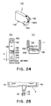
- Figure 24 is a schematic drawing for showing the structure of the ink container 7, Figures 24(a), 24(b), and 24(c) being an external perspective view of the ink container 7, a plan view of the bottom surface of the ink container 7, and a sectional view of the ink container 7 at Plane A-A in Figure 24(a), respectively.
- a referential numeral 200 designates the head holder into which the above described ink container 7 is mounted, and which is integral with the recording head. It holds, for example, ink containers 7 (7C, 7M, and 7Y) for containing cyan (C), magenta (M), and yellow (Y) inks, respectively.
- the bottom portion of the head holder 200 has the recording head 1, which ejects the above listed color inks, and which is an integral part of the bottom portion of the head holder 200.
- the bottom portion of the head holder 200 also has a window (unshown) through which the ink presence (absence) and ink container presence (absence) can be detected by an ink presence (absence) detecting portion, and an ink container presence (absence) detecting portion, respectively.
- the ink container 7 has a triangular notch 250, which is at the bottom edge of the side wall.
- the ink container 7 also has a prism 180 and a concave reflective portion 190.
- the prism 180 is attached to the bottom surface of the ink container 7.
- the concave reflecting portion 190 is an integral part of the bottom wall of the ink container 7, and faces outward of the ink container 7.
- the prism 180 is used for detecting the remaining amount of the ink in the ink container 7, and the concave reflective portion 190 is used for detecting the ink container presence or absence.
- the concave reflective portion 190 is structured so that the entirety of its reflective surface is concavely arcuate in terms of the direction in which the ink container 7 borne on the carriage shuttles as the carriage is shuttled, that is, the moving direction of the carriage, as well as the direction (direction F) in which the light emitting element 15 and photosensitive element 16 are aligned, that is, the direction perpendicular to the moving direction of the carriage.
- Figure 25 shows ink containers, the optical unit 14 of each of which is at the normal position.
- the light emitting portion of the light emitting element 15 of the optical unit 14, and the photosensitive portion of the photosensitive element 16 of the optical unit 14, are near the center 18 of the concavely arcuate surface of the concave reflective portion 190. Further, they are in such positions that the central axis of the beam of infrared red light emitted from the light emitting element 15 is parallel to the direction perpendicular to the bottom wall of the ink container 7.
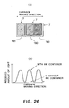
- Figure 26(A) shows the structure of the bottom portion of each of the plurality of ink containers 7 containing the plurality of color inks, one for one, and Figure 26(B) shows the difference among the plurality of the ink containers 7, specifically in the amount of the light reflected by their bottom surfaces.
- three ink containers 7, which contain three inks, one for one, different in color (yellow (Y), magenta (M), cyan (C)), are disposed side by side and in parallel.
- Each ink container 7 has its own concave reflective portion 190.
- the prior art regarding a liquid container, as an ink container, having the above described optical reflective portion has the following problems.
- the resinous material for an ink container must be selected in consideration of its compatibility with ink, cost, etc.
- a resinous substance is not ideal in terms of optical properties.
- an ink container is provided with a concave reflective portion, such as the above described one, to condense the light it receives, it is necessary that the amount by which the light emitting portion emits light is substantial, or the light emitting portion is provided with a condenser lens, and/or that a very sensitive sensor is employed as the sensor of the photosensitive portion.
- Japanese Laid-open Patent Application 9-174877 discloses an ink container as the solution to the above described problem.
- the reflective surface of the ink container (liquid container) is improved in reflectivity, by making it into a mirror by deposition, or placing a piece of reflective film thereon.
- this type of improvement in reflectivity there is a sufficient amount of difference in intensity between the reflected light from the reflective portion and the reflected light from the nonreflective portion.
- improving the reflective portion of an ink container is one of the effective means for detecting the ink container presence.
- giving the above described treatment to an ink container, which is considered to be expendable increases the ink container cost, which adds to the cost of an ink jet recording apparatus.
- the means for identifying (detecting) an ink container in terms of the color of the ink therein, with the use of the above described reflective optical member, it is possible to make a plurality of ink containers different in the positioning of the reflective optical member, according to the color of the ink therein.
- This method is problematic for the following reason. That is, in recent years, there has been made a substantial amount of progress in the field of the technology for printing a multicolor image with the use of an ink jet recording apparatus. Therefore, a plurality of ink containers are disposed in a limited space, making it difficult to vary the plurality of ink containers different in the positioning of the reflective optical portion for the purpose of identifying the color of the ink in each ink container.
- each ink container According to which a reflective optical member is attached to each ink container, and its positioning relative to each container is varied based on the color of the ink therein, making it possible to identify the plurality of ink containers on a carriage, the ratio, in terms of size, of each reflective optical member relative to the bottom surface of each ink container remains the same regardless of the number (6 - 7) of ink containers different in the color of the ink therein.
- each ink container must have six or seven different areas, to one of which a reflective optical member is attached for identification.
- the ratio, in terms of size, of the total of the areas (6 - 7) to one of which a reflective optical member is attached, relative to the bottom surface of the ink container, is rather large.
- a relatively large area must be reserved for the ink container identification in terms of the color of the ink therein, reducing the latitude in ink container design.
- the size of the area, the reflected light from which is to be detected, is greater, possibly making it necessary to increase the number of detecting apparatuses.
- each reflective optical member it is also possible to reduce the size of each reflective optical member so that the total size of six to seven areas of an ink container, to one of which a reflective optical member is attached for identification, remains small enough to occupy a relatively small portion of the bottom surface of an ink container.
- This arrangement reduces the size of the reflective surface, reducing therefore the intensity of the reflected light, which in turn may result in an erroneous detection.
- the side which receives the reflected light identifies a given ink container, as the reflective light from the given ink container arrives, or as the reflective light from the given ink container is detected by an amount greater than a set value.
- a small range in terms of light intensity must be divided into six to seven sub-ranges different in light intensity.
- the side (light emitting element) which emits light is high in output. The provision of a high output light emitting element increases the cost of the main assembly of an ink jet printer, and/or its power consumption, which is problematic.
- the present invention is made in consideration of the above described problems in the prior art, and the primary object of the present invention is to provide a liquid container which can be identified in terms of the color of the ink therein, even if the liquid container (ink container) is erroneously mounted, and the state of mount (whether or not liquid container is "floating" from liquid container mounting portion, which hereinafter may be referred to as incomplete mounting) of which can be detected, in order to prevent a recording apparatus from recording an image different from an intended image, and also to provide a method for identifying a liquid container, as well as detecting the incomplete mounting of a liquid container.
- a liquid container for containing liquid comprising a reflection member having a plurality of roof mirror assemblies arranged in a predetermined direction, each of said roof mirror assemblies having at least two reflecting surfaces positioned with a predetermined angle therebetween; wherein said reflection member is effective to divide incident light into a plurality of light beams by said plurality of roof mirror assemblies and to condensing at a predetermined position the beams sequentially reflected by the at least two reflecting surfaces of the roof mirror assemblies. wherein said reflection member is effective to divide incident light into a plurality of light beams by said plurality of roof mirror assemblies and to condensing at a predetermined position the beams sequentially reflected by the at least two reflecting surfaces of the roof mirror assemblies.
- the incident light which is divergent is reflected and condensed one- or two- dimensionally by said reflection member.
- the container further comprises an additional roof mirror assembly having reflecting surfaces which are positioned at a different predetermined angle such that reflected light which converges one- or two- dimensionally is divided and converged to different areas.
- a light emitting element is disposed in a projected area of said reflection member below said reflection member such that reflected light is divided and converged to different areas.
- the predetermined angle is no 90 degrees.
- the plurality of said reflection members are disposed so that reflected light which converges one- or two- dimensionally is divided and converged to different areas.
- a liquid container for containing liquid comprising a reflection member having a plurality of roof mirror assemblies arranged at predetermined positions, each of said roof mirror assemblies having at least two reflecting surfaces positioned with a predetermined angle therebetween; wherein said roof mirror assemblies are arranged successively in a predetermined direction.
- a space is provided at a position of contact relative to said roof mirror assembly.
- a discriminating method for a liquid container for containing liquid
- said liquid container includes a reflection member having a plurality of roof mirror assemblies arranged in a predetermined direction, each of said roof mirror assemblies having at least two reflecting surfaces positioned with a predetermined angle therebetween, and said reflection member divides incident light into a plurality of light beams by said plurality of roof mirror assemblies so that light beams reflected sequentially by at least two reflecting surfaces of each of said roof mirror assemblies are condensed at predetermined positions
- said method comprising the step of discriminating said liquid container on the basis of a distribution pattern of the reflected light constituted by the condensed light beams.
- a method for detecting a mounting state of a liquid container for containing liquid wherein said liquid container includes a reflection member having a plurality of roof mirror assemblies arranged in a predetermined direction, each of said roof mirror assemblies having at least two reflecting surfaces positioned with a predetermined angle therebetween, and wherein said reflection member is effective to divide incident light into a plurality of light beams by said plurality of roof mirror assemblies and to condensing at a predetermined position the beams sequentially reflected by the at least two reflecting surfaces of the roof mirror assemblies, said method comprising detecting a mounting state of said liquid container on the basis of a change in a position of the reflected light constituted by the condensed light beams.
- information relating to said liquid container is discriminated on the basis of a width of the reflected light from said reflection member.
- information relating to said liquid container is discriminated on the basis of a number of the reflected light portions having peaks.
- information relating to said liquid container is discriminated on the basis of a pitch of a pattern of the reflected light.
- said liquid container is discriminated on the basis of a difference in peak values of the reflected light from said reflection member.
- said liquid container is discriminated on the basis of a difference in widths of the reflected light from said reflection member.
- said liquid container is discriminated on the basis of a difference in numbers of the reflected light from said reflection member.
- said liquid container is discriminated on the basis of intervals of the reflected light from said reflection member.
- the information relating to said liquid container is discriminated on the basis of diffracted light from said reflection member.
- a liquid ejection type recording apparatus for effecting recording by ejection of liquid from a liquid container, said apparatus comprising a carriage capable of carrying said liquid container which has a structure as defined above; first detecting means for discriminating said liquid container; and second detecting means for detecting a mounting state of said liquid container in said apparatus.
- said first and second detecting means include point light source means and light receiving means.
- the light source means emit divergent light.
- said light source means and said light receiving means are integral with each other.
- an optical reflective member comprising a plurality of roof-shaped mirrors micro-processed so that the reflective surfaces of each roof-shaped mirror are positioned at a predetermined angle relative to each other, is formed of an optically transparent substance, and is placed on a liquid container so that its reflective surface (interface) is in contact with a substance (gas in following embodiments) significantly different in refractive index from the reflective member.
- a liquid container can be identified in terms of the color of the ink therein, using the difference in the pattern of the distribution curve of the amount of the reflected light from the reflective surfaces of each of the roof-shaped mirrors of the reflective member, positioned at the predetermined angle relative to each other, more specifically, the position, pitch, magnitude, etc., of the peaks of the distribution curve. Further, the state of mount (incomplete mounting) of a liquid container is detected based on the deviation of the spot on the photosensitive element, onto which the reflected light from the reflective member on the liquid container, condenses, from the normal spot.
- the reflective portion of a reflective member is made up of a plurality of roof-shaped mirrors, capable of condensing the reflective light onto an optional spot. Therefore, the present invention makes it possible to reduce the amount of the space a reflective member requires on a liquid container (ink container), and also to increase the amount of the light a reflective member reflects without performing a special process, for example, deposition of reflective film, on the reflective surface of the reflective member. Further, each reflective member can be made different from the other reflective members, in the pattern of the distribution curve of the amount of the reflective light from a reflective member, received by the light receiving side.
- a reflective member different in the configuration and arrangement of roof-shaped mirrors, from the other reflective members, can be placed on each liquid container (ink container), so that each liquid container (ink container) can be identified in terms of the color of the ink therein, and further, the state of mount (incomplete mounting) of each liquid container can be detected based on the deviation of the spot on the photosensitive element, onto which the reflective light from the reflective member on the liquid container condenses, from the normal spot.
- Figure 1 is a drawing for describe the optical properties of a reflective member for a liquid container in accordance with the present invention.
- Figure 1(a) is a perspective view of the reflective member
- Figure 1(b) is a sectional view of the combination of the reflective member and a detecting apparatus, as seen from the direction "1" in Figure 1(a), for showing the optical relationship thereof.
- Figure 1(c) is a sectional view of the combination of the reflective member and detecting apparatus, as seen from the direction "2" in Figure 1(a), for showing the optical relationship thereof.
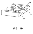
- each reflective member 30 is transparent (formed of transparent resin, for example), and comprises a plurality of "daha” prisms (which hereinafter will be referred to as roof mirror, for convenience), arranged in parallel.
- a "daha” prism is a prism which is V-shaped in cross section, and has a pair of reflective surfaces positioned relative to each other at a predetermined angle (90° in this embodiment). More specifically, the top surface of the reflective member 30 has a plurality of rows of roof-shaped mirrors 34 disposed in parallel, and the bottom surface of the reflective member 30 is flat.
- the pitch P2 of the roof mirror in Figure 1 is 84 ⁇ m, for example. The measurement of each roof mirror is 84 ⁇ m x 100 ⁇ m.
- a detecting apparatus comprises a point-source light 31 in the form of a photo IC chip, and a photosensitive element 32. It is disposed so that it will be below the reflective member 30, with the presence of a predetermined gap between the bottom surface of the reflective member 30 and the light receiving surface of the photosensitive element 32, when an ink container in accordance with the present invention is properly positioned in an ink jet recording apparatus.
- the light emitting side is discrete from the light receiving side. However, the two sides may be integral; in reality, an integral type emitting/receiving element is in use.
- the outward surface of the reflective member 30, having a contour like a row of roofs 34 is in contact with a substance, which is substantially different in refractive index from the material of the reflective member 30, and which is not in liquid form.
- the paths of the light 3000 from the light emitting side to the receiving side are represented by the combinations of solid lines and single-dot chain lines, showing the manner in which the light 3000 emitted from the emitting side (point-source light 31) are condensed after being reflected by the reflective member 30.
- the single-dot chain lines in the drawing represent the light paths after the reflection of the light by the roof mirrors 34.
- the light emitting side is not equipped with a condensing means, such as a lens. Therefore, the light 3000 is divergent.
- the light 3000 (divergent light) projected from the point-source light 31 passes through the transparent reflective member 30, is reflected twice by the processed two surfaces, one for one, of the roof mirror 34, positioned relative to each other at a predetermined angle, and returns, being thereby condensed approximately in the form of a belt, to an optional point on the light receiving side (photosensitive element 31 in the form of an array).
- the returning light, or the reflected light is convergent in terms of one-dimensional direction.
- a grid image, the pitch of which is twice the pitch P of the reflective member is projected as shown in Figure 1(c).
- a reflective member in accordance with the present invention employs a reflecting means which makes light condense only in terms of one dimension.
- the characteristics of this reflective member will be described in comparison to an ordinary reflective member, the reflective surface of which is flat and is coated with aluminum film.
- Figure 2 is a schematic drawing for describing an ordinary reflective member, the reflective surface of which is flat and is coated with aluminum film. It shows the light paths of the flux of light from the light source 31 of the photosensor PS to the photosensitive element 32 by way of the reflective surface 30a1 of the reflective member 30.
- the detecting means comprises: the light source 1; photosensitive element 32, the light receiving surface of which is PDWy x PDWx in size; and reflective member 30, the reflective surface 30a1 of which is coated with reflective aluminum film.
- the dotted lines in the drawing represent the light paths from the light source 1 to photosensitive element 32 by way of the reflective member 30.
- the size of the photosensitive element 32 is 400 ⁇ m
- the size of the above described portion of the aluminum reflective film 30a1, corresponding the effective flux of light is approximately 200 ⁇ m. In other words, the amount of the light from the light source 31, which arrives at the photosensitive element 32, is very small.
- the relationship between the gap (distance) between the photosensor PS and reflective member 30, and the amount of light received by the photosensitive element 32 is as follows: amount of light ⁇ 1/(distance) 2 .
- Figure 3 is a schematic drawing for showing the light paths between the reflective member 30, for a liquid container in accordance with the present invention, with the V-shaped reflective surfaces (which sometimes may be referred to as roof mirror), and the photosensitive element 32.
- each of the V-shaped grooves in Figure 3 are assumed to be virtually equal in reflectivity to the above described aluminum reflective film.
- the angle (Ra) between the two reflective surfaces of the V-shaped groove is set to approximately 95 degrees so that the light paths become approximately the same as the preceding setup.
- the light paths in this setup are similar to the light paths in the preceding setup shown in Figure 2(B); there are virtually no differences between them.
- FIG 4 is a schematic drawing of the reflective member 30 comprising a plurality of V-shaped grooves (which sometimes may be referred to as roof mirror unit).
- This drawing shows the approximate light paths through which the light from the light emitting element 31 of the photosensor PS is guided to the array of the photosensitive elements 32 by the reflective member 30.
- This reflective member 30 also guides a larger ratio of the light from the light emitting element 31 to the photosensitive elements 32 than the reflective member 30, shown in Figure 2, having the flat aluminum reflective film.
- Figure 5 is a schematic drawing for describing one of the effects of a reflective member for an ink container in accordance with the present invention different from the above described one. This effect relates to the properties of the gap (distance) between the photosensor PS and reflective member 30.
- Figure 5(A) represents a setup in which the photosensor PS and/or reflective member 30 have been moved away from the standard positions in order to increase their distance
- Figure 5(B) represents the setup in which they are at their standard positions.
- the amount of light detected by the photosensitive element is practically proportional to 1/(distance) 2 . Therefore, if the gap 30002 in Figure 5(A), equivalent to the distance between the reflective member and photosensor PS shown in Figure 2, is twice, for example, the gap 3002 in Figure 5(B), the total length of the light path, that is, the sum of the distance of the light path from the light emitting element to the reflective member, and the distance of the light path from the reflective member to the photosensitive member, in Figure 5(A), is also twice that in Figure 5(B). Therefore, the amount of the light detected by the photosensitive element 32 in Figure 5(A) is approximately 25%, in practical terms, of the amount of the light detected by the photosensitive element in Figure 5(B).
- the amount of the light detected by the photosensitive elements 32 in terms of the direction parallel to the plane of Figure 3(A), is not dependent on the gap (distance), as will be understood from Figures 5(A) and 5(B).
- the amount of the light detected by the photosensitive element in terms of the direction parallel to the plane of Figure 3(B), may be said to be proportional to 1/distance.
- a reflective member of an ink container in accordance with the present invention is also superior in terms of the effect of the changes in this gap upon the amount of the light detected by the photosensitive element.
- FIG. 6 is a schematic drawing for describing another effect of a reflective member of an ink container in accordance with the present invention.
- this reflective member is also superior in that even if the angle ( ⁇ ) of the reflective member 30 relative to the photosensor PS changes, the manner in which the light from the light source is guided to the photosensitive portion 32 by the reflective member 30 remains virtually the same; the changes in the angle ( ⁇ ) of the reflective member 30 relative to the photosensor PS have virtually no effect upon the amount of the light received by the photosensitive portion 32.
- the employment of the reflective member 30 having a single or plurality of V-shaped grooves has merit in that it is greater in the absolute amount by which the light from the light emitting element 31 is guided to the photosensitive portion 32 of the photosensor PS than the reflective member, shown in Figure 2, the reflective surface of which is flat.
- the reflective surface of which has a single or plurality of V-shaped grooves, even if the distance (gap) between the reflective member and photosensor varies, there is hardly any change in the amount by which the light from the light emitting element is detected by the photosensitive element.
- the amount by which the light from the light emitting element is detected by the photosensitive element is insensitive to the changes in the angle ( ⁇ ) between the photosensor and reflective member; even if the angle ( ⁇ ) changes, the amount of the light detected by the light receiving portion reduces very little.
- Figure 7(A) is a schematic sectional view of the above described reflective member, at a plane perpendicular to the V-shaped grooves, for describing the above described reflective properties of the reflective member.
- a cylindrical member, the lateral wall of which has a plurality of V-shaped grooves, as shown in Figure 7(B) is obtained.
- the present invention is characterized in that a part of the V-shaped groove on the lateral surface of such a cylindrical member is used as a reflective target; the present invention is characterized by the "second reflective function" of the reflective member.
- the reflective member comprises a plurality of roof mirrors or roof prisms, the reflective surfaces of which are curved in terms of the lengthwise direction of the grooves, and a part of which serves as the reflective identification target OE.
- the reflective element OE is comparable to a combination of the lateral surfaces of two identical truncated cones.
- Figure 7(C) is a schematic sectional view, at a plane parallel to the grooves, of an example of a reflective member made up of a plurality of the above described reflective element (OE) disposed in parallel, being aligned in the direction of Y axis
- Figure 7(D) is a schematic perspective view of the reflective member in Figure 7(C).
- the referential sign Ro is the rotation symmetry axis of the above described V-shaped grooves
- a referential sign CC is a point on the rotation symmetry axis.
- a point FP is the point, to which the reflected light from the reflective member condenses when the reflective member is illuminated by divergent light from a light source disposed at this point.
- the roof mirrors of a reflective member which arranged on a flat surface, as shown in Figures 1 - 6, are arranged on a cylindrical surface as shown in Figure 7, or a spherical surface (unshown), the reflected light from the reflective member condenses two-dimensionally.
- the reflective member 30 in accordance with the present invention having the roof mirrors will be described with reference to an ink container 7 (liquid container) comprising: an ink absorbent member chamber 42 storing an ink absorbent member 41 formed of sponge or the like; a liquid storage chamber 45 directly storing a body of ink 44; a passage 44 connecting the ink absorbent member chamber 42 and liquid storage chamber 45; and an ink outlet 46, which is attached to the ink absorbent member chamber 42, and through which the ink within the liquid container 7 is supplied to an ink jet recording head (unshown) which records an image by ejecting the ink as recording liquid.
- the reflective member 30 in accordance with the present invention having a roof mirror can be used for any liquid container.
- the reflective member 30 will be described with reference to only the structural arrangement in which the reflective member 30 is disposed on the bottom surface of a liquid container. However, it may be disposed on any surface of a liquid container, except for the surface which faces the next liquid container (ink container), affording more latitude in the positioning, for example, of the light receiving apparatus on the main assembly side of an ink jet recording apparatus ( Figure 21).
- the reflective member 30 is disposed in a recess in the wall 7a of the ink container 7 so that the roof mirrors 34 making up the top surface of the reflective member 30 remains in contact with a nonliquid substance (air in this case) substantially different in reflectivity from the transparent resin as the material for the reflective member 30; the reflective member 30 is disposed in the recess of the wall 7a of the ink container 7, with the presence of a space 47 between the roof mirrors and the bottom of the recess.
- This reflective member 30 is compatible with various liquid containers (ink container), as long as a reflective member is formed of transparent resin, and is structured so that it can be disposed so that its reflective surface remains in contact with a substance different in reflectivity from the reflective member.
- Using transparent resin as the material for the reflective member 30 makes it possible to form the reflective member 30 with the use of injection molding or the like, which simplifies the reflective member manufacture.
- the ink container 7 is removably mountable, alone or in plurality, on the carriage of an ink jet recording apparatus, which shuttles in the direction perpendicular to the direction in which recording sheet is conveyed.
- a plurality of ink containers 7 are mounted on the carriage, they are disposed side by side in parallel so that the lengthwise direction of the ink containers becomes parallel to the shuttling direction of the carriage.
- the adjacent two roof mirror portions of the reflective member 30 are separated by a portion 35 through which the light from below is allowed to pass upward.
- This portion 35 may be in the form of a wall with a flat top, higher than the ridges of the reflective surface of each roof mirror portion, as shown in Figure 1(a), or may be in the form of a recess flat across the bottom.
- the configuration of this portion 35 may be modified according to the production method and the required degree of precision.
- the reflective member 30 will be schematically drawn without the presence of the above described portions 35, as shown in Figure 9(b), Figure 10(b), etc., for simplification, and will be described accordingly.
- Embodiments 1 - 6 relate to the structure of the reflective member for identifying a liquid container in terms of the color of the liquid therein
- Embodiment 8 relates to the structure of the reflective member for detecting whether or not a liquid container is in the proper position (improper position) in the liquid container mounting portion of a liquid ejecting apparatus.
- Figure 9 is a schematic drawing for describing the first embodiment of a reflective member in accordance with the present invention.
- Figure 9(a) is an enlarged view of the roof mirror portion of the reflective member on the bottom surface of an ink container and
- Figure 9(b) is a perspective view of the roof mirror portion of the reflective member.
- Figure 9(c) is a graph showing the distribution of the amount of the light received by the light receiving side when a liquid container has the first embodiment of a reflective member, in which the roof mirrors are positioned as shown in Figure 9(b).
- Figure 9 is a perspective view, as seen from diagonally above, of the side of the reflective member, which faces inward of a liquid container as the reflective member is attached to the liquid container.
- this embodiment of the present invention will be described in detail.
- the reflective member 30 has first and second roof mirror units (reflective members) 30A and 30B, and is on the bottom wall of the ink container 7, with the lengthwise direction of its roof mirrors being parallel to the moving direction A (direction in which carriage is moved) of the ink container 7.
- the first roof mirror unit 30A has eight roof mirrors 34A
- the second roof mirror unit 30B has four roof mirrors 34B.
- the roof mirror 34A and roof mirror 34B are the same in terms of the depth (dimension in terms of moving direction A), and the angle between two reflective surfaces.
- the information regarding each ink container 7 can be obtained by detecting the values of the peaks (1) and (2) of the distribution curve of the amounts of the light received by the first and second roof mirror units 30A and 30B, respectively, and also, the difference (3) between the values of the two peaks (1) and (2).
- the reflective member on each ink container is made different from the reflective members on the other ink containers, in terms of the value of the peak of the distribution curve of the amount of the light received by the photosensitive element, different among the peaks, so that the plurality of ink containers can be differentiated.
- the peak mentioned in the present invention is the peak or peaks of the distribution curve showing relationship between the amount of the light received by the photosensitive element and the elapse of time (X axis) from the beginning of the carriage movement.
- This embodiment is a modification of the first embodiment; it is different from the first embodiment in that the first mirror unit is different in the roof mirror depth from the second mirror unit. Next, this embodiment will be described in detail.
- Figure 10 is a drawing for describing the second embodiment of a reflective member in accordance with the present invention.
- Figure 10(a) is an enlarged view of the roof mirror portion of the reflective member on the bottom surface of an ink container
- Figure 10(b) is a perspective view of the roof mirror portion of the reflective member.
- Figure 10(c) is a graph showing the distribution of the amount of the light received by the light receiving side when a liquid container has the second embodiment of a reflective member, the roof mirrors of which are positioned as shown in Figure 10(b).
- the reflective member 30 has first and second roof mirror units (reflective members) 30A and 30B, and is on the bottom wall of the ink container 7, with all roof mirrors being arranged in parallel so that their lengthwise direction is parallel to the moving direction A of the ink container 7.
- first and second roof mirror unit 30A and 30B are identical.
- the roof mirror depth dimension in terms of moving direction A
- the information regarding each ink container 7, the durations (3) and (4) of the time the reflective light is received are determined by the depths of the roof mirror units 30A and 30B on the bottom surface of the ink container.
- the information regarding each ink container can be recognized by detecting the durations (3) and (4) corresponding to the peaks (1) and (2), or the difference between the durations (3) and (4).
- the reflective member on each ink container is made different from the reflective members on the other ink containers, in terms of the depth of a roof mirror, so that the plurality of ink containers can be differentiated based on the duration of time the reflected light from each roof mirror unit is received, difference between the durations of time corresponding to two roof mirror units on the reflective member, difference, in terms of the duration of time the reflected light is received, among the plurality of ink containers.
- This method, described above, for identifying an ink container based on the duration of time the reflective light is received has merit in that the duration of time the reflected light is received is not likely to change even if the amount of the reflected light is reduced by the mist, which is a problem peculiar to an ink jet.
- This embodiment is another modification of the first embodiment; it is different from the first embodiment in that the first mirror unit is different in the number of roof mirrors from the second mirror unit. Next, this embodiment will be described in detail.
- Figure 11 is a schematic drawing for describing the third embodiment of a reflective member in accordance with the present invention.
- Figure 11(a) is an enlarged view of the roof mirror portion of the reflective member on the bottom surface of an ink container
- Figure 11(b) is a perspective view of the roof mirror portion of the reflective member.
- Figure 11(c) is a graph showing the distribution of the amount of the light received by the light receiving side when a liquid container has the third embodiment of a reflective member, in which the roof mirrors are positioned as shown in Figure 11(b).
- the reflective member 30 has first, second, and third roof mirror units 30A, 30B, and 30C, and is on the bottom wall of the ink container 7, being disposed so that all roof mirrors are parallel to the moving direction A of the ink container 7.
- the first, second, and third roof mirror units 30A, 30B, and 30C are the same.
- the pitch B between the first and second mirror units 30A and 30B is different from the pitch C between the second and third mirror unit 30B and 30C.
- the pitch (4) between the first and second peaks (1) and (2) is determined by the pitch B between the first and second roof mirror units 30A and 30B
- the pitch (5) between the second and third peaks (2) and (3) is determined by the pitch C between the second and third roof mirror units 30B and 30C.
- the information regarding each ink container 7 can be obtained by detecting the number of the peaks (in this case, three: peaks (1), (2), and (3)), and the pitches (4) and (5) between the adjacent two peaks.
- the information regarding each ink container can be obtained based on the points in time at which the peaks (1), (2), (3) are detected. In other words, it can be obtained by detecting the absolute position of the reflective member relative to the ink container on which the reflective member is.
- the plurality of ink containers 7 placed in parallel on the carriage can be identified in terms of the color of the ink therein, by placing a reflective member different, in the number, position, and pitch of the roof mirrors, from the other reflective members, on each of the plurality of ink containers 7, so that they can be identified by detecting the difference in the number of the peaks of the distribution curve of the amount of the reflective light received by the photosensitive element, pitch between the adjacent two peaks of the distribution curve, and timing of the reflective light reception, among them.
- the number of the peaks of the above described distribution curve can be detected, as long as the amount of the reflected light detected by the photosensitive element is greater than a certain threshold value (threshold value can be set low).
- this identification method described above, based on the number of the above described peaks, can tolerate the differences among the reflective members which occur during the manufacture of the reflective members, providing the benefit of making it relatively easy to manufacture the reflective members, making therefore it possible to reduce the liquid container cost.
- This embodiment is an example of a reflective member in accordance with the present invention, having only one roof mirror unit which has two subunits different in the angle of the two reflective surfaces of a roof mirror. It is assumed in this case that the measuring area of the sensor on the light receiving side is dividable. Next, the details of this embodiment will be described.
- Figure 12 is a schematic drawing for describing the fourth embodiment of a reflective member in accordance with the present invention.
- Figure 12(a) is an enlarged view of the roof mirror portion of the reflective member on the bottom surface of an ink container
- Figure 12(b) is a perspective view of the roof mirror portion of the reflective member in Figure 12(a).
- Figure 12(c) is a drawing for showing the optical relationship between the reflective member and detecting apparatus (photosensitive element, light emitting element) in this fourth embodiment of the present invention.
- Figures 13(a) and 13(b) are graphs showing the distribution curves of the amount of the light received by the light receiving side of the fourth embodiment, in which the roof mirrors are disposed as shown in Figure 12(b).
- the reflective member 30 has a single roof mirror unit having eight roof mirrors, and is on the bottom wall of the ink container 7, being disposed side by side in parallel so that all roof mirrors are parallel to the moving direction A of the ink container 7. In terms of the depth (dimension in terms of carriage movement direction), all the roof mirrors are the same. However, the reflective member 30 has two sections: a first section having five roof mirrors 34a, counting from the right side of the drawing, and a second section having the next three roof mirrors 34b. The roof mirror 34a and roof mirror 34b are different in the angle between at least the two reflective surfaces of a roof mirror.
- the reflective member being structured as described above, the light emitted from the point-source light 31 toward the reflective member 30 is reflected by the first and second sections of the reflective member 30, having the roof mirrors 34a and roof mirrors 34b, respectively, into two fluxes of reflected light, which are condensed onto the photosensitive element 32.
- the point-source light 31 and photosensitive element 32 are disposed within the range of the downward projection of the reflective member 30, as shown in Figure 12(c).
- the roof mirrors 34a and roof mirrors 34b can be illuminated by the point-source light 31 may be disposed outside the range of the detection area of the photosensitive element.
- the roof mirror units of which are in the above described configuration and arrangement As the ink container 7 having the reflective member 30, the roof mirror units of which are in the above described configuration and arrangement, is moved in the direction A by the carriage, the distribution of the amount of the light received by the portion of the photosensitive element corresponding to the first section (34a) of the reflective member 30, and the distribution of the amount of the light received by the portion of the photosensitive element corresponding to the second section (34b) of the reflective member 30, become as shown in Figures 13(a) and 13(b), respectively.
- the information regarding each ink container can be recognized by measuring the amount of the reflective light (1) received by the point of the light receiving side corresponding to the aforementioned first section of the reflective member 30 and the amount of the reflective light (2) received by the point on the light receiving side corresponding to the second section of the reflective member, shown in Figures 13(a) and 13(b), detecting thereby difference in the peak value of the amount of the reflected light between the first and second sections of the reflective member, described regarding the first embodiment ( Figure 9), the duration of the time the reflective light is received by the first and second sections of the reflective member, described regarding the second embodiment ( Figure 10), the pitch between the adjacent peaks, timing of the reflective light reception, difference in the reflective light reception point on the light receiving side between the first and second sections of the reflective member, described regarding the third embodiment ( Figure 11).
- each ink container only one reflective member 30 is disposed on each ink container.
- two or more reflective members 30 may be disposed in parallel on each ink container.
- This embodiment is an example of a reflective member in accordance with the present invention, having only one roof mirror unit which has two subunits different in the roof mirror count. It is assumed in this case that the measuring area of the sensor on the light receiving side is dividable. Next, the details of this embodiment will be described.
- Figure 14 is a schematic drawing for describing the fifth embodiment of a reflective member in accordance with the present invention.
- Figure 14(a) is an enlarged view of the roof mirror portion of the reflective member on the bottom surface of an ink container
- Figure 14(b) is a perspective view of the roof mirror portion of the reflective member in Figure 14(a).
- Figure 14(c) is a drawing for showing the optical relationship between the reflective member and detecting apparatus (photosensitive element, light emitting element) in this fifth embodiment of the present invention.
- Figures 14(a) and 14(b) are graphs showing the distributions of the amount of the light received by the light receiving side of the fifth embodiment, in which the roof mirrors are disposed as shown in Figure 14(b).
- this embodiment of a reflective member 30 has a single roof mirror unit having eight roof mirrors, and is on the bottom wall of the ink container 7, being disposed so that all roof mirrors are parallel to the moving direction A of the ink container 7. In terms of the depth (dimension in terms of carriage movement direction), all the roof mirrors are the same.
- the reflective member 30 has two sections: first section having five roof mirrors 34a, counting from the right side of the drawing, and second section having the next three roof mirrors 34b.
- the first and second sections (34a) and (34b) of this embodiment of the reflective member 30 are different in the roof mirror pitch, although they are the same in the angle between at least the two reflective surfaces of each roof mirror.
- the light emitted from the point-source light 31 toward the reflective member 30 is divisively reflected by the first and second sections of the reflective member 30, having the roof mirrors 34a and roof mirrors 34b, respectively, into two fluxes of reflected light, which are condensed onto the photosensitive element 32.
- the point-source light and photosensitive element 32 are disposed within the range of the downward projection of the reflective member 30, as shown in Figure 14(c).
- the roof mirrors 34a and roof mirrors 34b can be illuminated by the point-source light 31 may be disposed outside the range of the detection area of the photosensitive element.
- the roof mirror units of which are in the above described configuration and arrangement As the ink container 7 having the reflective member 30, the roof mirror units of which are in the above described configuration and arrangement, is moved in the direction A by the carriage, the distribution of the amount of the light received by the portion of the photosensitive element corresponding to the first section (34a) of the reflective member 30, and the distribution of the amount of the light received by the portion of the photosensitive element corresponding to the second section (34b) of the reflective member 30, become as shown in Figures 15(a) and 15(b), respectively.
- the information regarding each ink container can be recognized by measuring the amount of the reflective light (1) received by the point of the light receiving side corresponding to the aforementioned first section of the reflective member 30 and the amount of the reflective light (2) received by the point on the light receiving side corresponding to the second section of the reflective member, shown in Figures 13(a) and 13(b), detecting thereby difference in the peak value of the amount of the reflected light between the first and second sections of the reflective member, described regarding the first embodiment ( Figure 9), the duration of the time the reflective light is received by the first and second sections of the reflective member, described regarding the second embodiment ( Figure 10), the pitch between the adjacent peaks, timing of the reflective light reception, difference in the reflective light reception point on the light receiving side between the first and second sections of the reflective member, described regarding the third embodiment ( Figure 11).
- a reflective member different, in the roof mirror count and roof mirror pitch, from the other reflective members, is placed on each of the plurality of ink containers 7, so that they can be identified by detecting the peak values of the reflected light, difference in the peak value of the reflected light among the plurality of ink containers, described regarding the first embodiment, duration of the reflective light reception, difference in the duration of the reflected light reception among the plurality of ink containers, described regarding the second embodiment, pitch between the adjacent peaks of the aforementioned distribution curve, timing of the reflected light reception, difference in the point of the reflective light reception among the plurality of ink containers, described regarding the third embodiment.
- each ink container only one reflective member 30 is disposed on each ink container.
- two or more reflective members 30 may be disposed in parallel on each ink container.
- This embodiment of a reflective member in accordance with the present invention is a modification of the first to fifth embodiments, in terms of the reflective member arrangement. More specifically, the two roof mirror units which are disposed in the preceding embodiments are disposed perpendicular to each other. Next, the details of this embodiment will be described.
- Figure 16 is a schematic drawing for describing the sixth embodiment of a reflective member in accordance with the present invention.
- Figure 16(a) is an enlarged view of the roof mirror portion of the reflective member on the bottom surface of an ink container
- Figure 16(b) is a perspective view of the roof mirror portion of the reflective member in Figure 16(a).
- Figure 16(c) is a graph showing the distribution of the amount of the light received by the light receiving side, on which the roof mirrors are disposed as shown in Figure 16(b).
- the reflective member 30 has first and second roof mirror units 30A and 30B, which are disposed in such a manner that the roof mirrors of the first mirror unit 30A are perpendicular to the roof mirrors of the second roof mirror unit 30A. More specifically, the roof mirrors 34a making up the first roof mirror unit 30A are perpendicular to the moving direction A of the ink container 7, whereas the roof mirrors 34b making up the second roof mirror unit 30B are parallel to the moving direction of the ink container 7. In terms of the depth (dimension in terms of carriage movement direction), roof mirror count, and angle between at least two reflective surfaces of a roof mirror, the first and second roof mirror units 30A and 30B are the same.
- each ink container In order to make it possible to identify each ink container, however, it is necessary to make each ink container different from other ink container, in one or more aspects, for example, roof mirror depth, roof mirror count, angle between the two reflective surfaces of a roof mirror, roof mirror pitch, etc., as presented in the descriptions of the preceding embodiments.
- the ink container 7 having the reflective member 30 As the ink container 7 having the reflective member 30, the roof mirror units of which are in the above described configuration and arrangement, is moved in the direction A by the carriage, the distribution of the amount of the light received by the light receiving side becomes as shown in Figures 16(c). This distribution of the amount of the light received by the photosensitive element is analyzed by the detecting apparatus to recognize the information regarding each ink container.
- the plurality of ink containers can be identified in terms of the color of the ink therein With the use of the various ink container identifying methods described regarding the preceding embodiments, based on the characteristics of the pattern of the distribution curve of the amount of the reflected light received on the photosensitive element side, for each ink container.
- Figure 17 is a drawing for describing the positioning (improper positioning; for example, "floating") of a liquid container in accordance with the present invention, relative to the liquid container mounting portion of an ink jet recording apparatus.
- Figure 17(a) is a drawing for showing the reflective member on the bottom surface of the ink container, light emitting element, and photosensitive element.
- Figure 17(b) is an enlarged perspective view of the roof mirror unit making up the reflective member on the bottom surface of the ink container.
- Figure 17(c) is a drawing for showing the light path through which the light from the light emitting element is condensed onto the photosensitive element.
- Figure 17(d) is a drawing for showing the light path through which the light from the light emitting element is condensed onto the photosensitive element, when the ink container is "floating".
- the roof mirror unit (reflective member) 30 is on the bottom surface of the ink container 7, with its roof mirrors being perpendicular to the moving direction A of the ink container (carriage movement direction).
- the direction in which the roof mirror unit is aligned is not limited to this direction; there are various ways of positioning the roof mirrors as in the first to sixth embodiments.
- each roof mirror is given such a dome shape that the center of its curvature is on the ink container side, as shown in Figure 17(b), and also that, in terms of the cross section parallel to the moving direction of the ink container, the reflective portion of the roof mirror unit (reflective member) is given such a dome shape that the center of its curvature is on the ink container side, as shown in Figure 17(b).
- the reflective portion of the roof mirror unit is given such a dome shape that the center of its curvature is on the ink container side, as shown in Figure 17(b).
- the ink container if the ink container is "floating" in the Z direction, the light reflected by the reflective member two-dimensionally condenses onto the spot on the photosensitive element, different from the spot onto which it would have condensed when the ink container was not "floating". Whether an ink container is in the normal position or "floating" can be detected by reading the amount of the deviation of the spot on the photosensitive element, onto which the light reflected by the reflective member of the ink container condenses, from the normal spot.
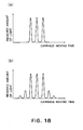
- Figure 18 is a drawing for describing the distribution of the amount of the diffracted portion of the light received by the photosensitive element. Referring to Figure 18(a), it is assumed that the distribution curve of the amount of the primary light received by the photosensitive element has three peaks. In reality, however, there will be other peaks, resulting from diffraction, before and after the three primary peaks, in terms of the time having elapsed from the beginning of the movement of the carriage, as shown in Figure 18(b). This secondary light resulting from the diffraction of the primary light can be read by the various ink container identification methods used with the first to sixth embodiments, in order to provide additional ink container identification methods.
- the ink container identification methods in accordance with the first and sixth embodiments, in order to provide additional methods for identifying an ink container in terms of the color of the ink therein.
- the distribution curve of the amount of the primary light received by the photosensitive element has three peaks as shown in Figure 18(a), there is, in reality, the peak of the distribution curve of the diffractive light between the adjacent peaks of the primary light.
- the reflective member employed a plurality of roof mirrors, which are shaped as shown in Figure 20(b-1) and are arranged as shown in Figure 20(a). Also, the light from the light emitting element is condensed onto the photosensitive element by being deflected twice by the roof mirror.
- the configuration of the roof mirror employed by the reflective member in accordance with the present invention does not need to be limited to the above described one. For example, it may be in the shape (triangular - polygonal pyramid) shown in Figures 20(b-2), or Figure 20(b-3). Further, it may be in the shape shown in Figure 20(b-4) (roof mirror is formed on cylindrical surface).
- the light from the light emitting element can be deflected twice as shown in Figures 20(c-2), 20(c-3), 20(c-4), and 20(c-5). Further, in the case of the preceding embodiments, the light from the light emitting element is deflected only twice. However, even if the light from the light emitting element is deflected more than twice due to the employment of a polygonal pyramid, it is possible to obtain the same effects as those obtained by the preceding embodiments.
- the ink container had two or more reflective members. It is obvious that even if a given ink container has only one reflective member, it is possible to identify the ink container as it is in the case of the first to sixth embodiments. In comparison, the seventh embodiment has only one reflective member. However, even if the seventh embodiment has two or more reflective members, it can be detected as it can be detected when it has only one reflective member.
- the number and configuration of a reflective member, as well as how a plurality of reflective members are arranged in combination are optional, as long as the space is available on the ink container. It is also possible to selectively combine the preceding embodiments according to ink color. For example, it is possible to employ an ink container having the first embodiment of a reflective member, as the ink container for magenta ink, and an ink container having the second embodiment of a reflective member, as the ink container for yellow ink.
- the reflective member is in the recess of the bottom wall of the ink container in such a manner that the processed surface (side having roof mirrors) of the reflective member faces the bottom of the recess, with the presence of a layer of gas between the processed surface and the bottom of the recess.
- the same effects as those obtained by the preceding embodiments can be obtained even if the need for this layer of gas is eliminated by depositing aluminum, or the like, on the processed surface of the reflective member, or by disposing the reflective member on the bottom surface of the ink container in such a manner that the processed surface of the reflective member faces outward of the ink container.
- the choice and placement of a reflective member are optional; they may be determined according to usage.
- the amount of the reflected light from the reflective member is detected as the ink container is moved.
- the detecting apparatus having the light emitting element and photosensitive element may be moved instead of moving the ink container.
- the resultant effects are the same as those obtained by the preceding embodiments.
- the light emitting element and photosensitive element may be discrete from each other as in the preceding embodiments, or may be integral.
- the manufacture date As for the information to be identified based on the above described pattern of the roof mirrors of the reflective member of the ink container, the manufacture date, types (color, model), properties (dye, pigment, viscosity, etc.), etc., are possible.
- the recording apparatus shown in Figure 21 is an ink jet recording apparatus, in which a plurality of ink containers equipped with the reflective member 30 having a single or plurality of the above described roof mirrors 34 are removably mountable. It comprises: a carriage 81, on which a head holder 200 having an ink jet recording head (unshown) is mounted; a head recovery unit 82 comprising a head cap for preventing the ink in the plurality of the orifices of the ink jet recording head, from drying, and a suction pump for suctioning the ink in the plurality of the orifices of the recording head as the recording head begins to improperly operate; and a sheet supporting plate 83 on which recording paper as recording medium is conveyed.
- the home position of the carriage 81 is where it aligns with the recovery unit 82.
- the carriage 81 is moved leftward of the drawing, in a scanning manner, as a belt 84 is driven by a motor or the like. While the carriage 81 is moved in a scanning manner, ink is ejected from the head toward the recording paper on the sheet supporting plate (platen) 83, forming an image on the recording paper.
- a liquid container is provided with a reflective member having a plurality of roof mirrors, at least two reflective surfaces of which are positioned at a predetermined angle relative to each other, and which are disposed side by side in parallel so that their reflective surfaces are intersectional to a predetermined direction. Therefore, the light which enters the reflective member is divided by the plurality of roof mirrors into a plurality of fluxes of light, which are condensed onto predetermined spots, one for one. Therefore, the application of the present invention makes it possible to increase the reflective efficiency of a reflective member without performing a special process, for example, vapor deposition of reflective film, or the like, on the reflective surface of the reflective member, making therefore it possible to reduce reflective member cost.
- the pattern of the distribution curve of the amount of the reflective light received by the photosensitive element can be varied in a large number of ways by varying the roof mirrors of the reflective member in specifications (pattern, count, width, etc.). Therefore, a plurality of reflective members different in the specifications (pattern, count, width, etc.) can be attached to a plurality of liquid containers, one for one, so that each liquid container can be identified in the color of the ink therein, based on the pattern, more specifically, positions of peaks, pitch of peaks, magnitude of peaks, etc., of the distribution curve of the amount of the reflective light received by the photosensitive element, and also so that whether or not each liquid container is in its proper position in an apparatus can be detected from the deviation of the spot, to which the light reflected by the reflective member of a given liquid container condenses, from the normal spot.
- the present invention it is possible to prevent a given liquid container from being erroneously mounted into an apparatus, more specifically, from being mounted into the liquid container mounting portion for a liquid container different in the color of the ink therein, or from being incompletely mounted in the apparatus, preventing therefore the apparatus from printing an incorrect image.
- a liquid container for containing liquid includes a reflection member having a plurality of roof mirror assemblies arranged in a predetermined direction, each of the roof mirror assemblies having at least two reflecting surfaces positioned with a predetermined angle therebetween; wherein the reflection member is effective to divide incident light into a plurality of light beams by the plurality of roof mirror assemblies and to condensing at a predetermined position the beams sequentially reflected by the at least two reflecting surfaces of the roof mirror assemblies. wherein the reflection member is effective to divide incident light into a plurality of light beams by the plurality of roof mirror assemblies and to condensing at a predetermined position the beams sequentially reflected by the at least two reflecting surfaces of the roof mirror assemblies.
Landscapes
- Ink Jet (AREA)
- Automatic Analysis And Handling Materials Therefor (AREA)
- Electrical Discharge Machining, Electrochemical Machining, And Combined Machining (AREA)
- Details Of Rigid Or Semi-Rigid Containers (AREA)
- Measurement Of Levels Of Liquids Or Fluent Solid Materials (AREA)
- Investigating Or Analysing Materials By Optical Means (AREA)
- Application Of Or Painting With Fluid Materials (AREA)
- Investigating Or Analysing Biological Materials (AREA)
Priority Applications (1)
| Application Number | Priority Date | Filing Date | Title |
|---|---|---|---|
| CL200400656A CL2004000656A1 (es) | 2002-03-29 | 2004-03-26 | Metodo y aparato para la generacion de una pulverizacion de un liquido sometiendolo a una atomizacion sobre una superficie de atomizacion, y producto. |
Applications Claiming Priority (2)
| Application Number | Priority Date | Filing Date | Title |
|---|---|---|---|
| JP2002095264A JP4018422B2 (ja) | 2002-03-29 | 2002-03-29 | 液体収納容器、および液体収納容器の識別方法 |
| JP2002095264 | 2002-03-29 |
Publications (3)
| Publication Number | Publication Date |
|---|---|
| EP1348560A2 true EP1348560A2 (fr) | 2003-10-01 |
| EP1348560A3 EP1348560A3 (fr) | 2004-04-28 |
| EP1348560B1 EP1348560B1 (fr) | 2008-09-17 |
Family
ID=27800546
Family Applications (1)
| Application Number | Title | Priority Date | Filing Date |
|---|---|---|---|
| EP03007055A Expired - Lifetime EP1348560B1 (fr) | 2002-03-29 | 2003-03-27 | Réservoir de liquide comprenant des moyens d'identification et procédé de surveillance de l'état de montage du réservoir de liquide |
Country Status (13)
| Country | Link |
|---|---|
| US (1) | US6869158B2 (fr) |
| EP (1) | EP1348560B1 (fr) |
| JP (1) | JP4018422B2 (fr) |
| KR (1) | KR100537974B1 (fr) |
| CN (1) | CN1282550C (fr) |
| AT (1) | ATE408507T1 (fr) |
| AU (1) | AU2003203491B2 (fr) |
| CA (1) | CA2423649C (fr) |
| CL (1) | CL2004000656A1 (fr) |
| DE (1) | DE60323554D1 (fr) |
| RU (1) | RU2003108819A (fr) |
| SG (1) | SG107137A1 (fr) |
| TW (1) | TW589447B (fr) |
Cited By (3)
| Publication number | Priority date | Publication date | Assignee | Title |
|---|---|---|---|---|
| EP1547781A2 (fr) | 2003-12-26 | 2005-06-29 | Canon Kabushiki Kaisha | Réservoir de liquide et système d'alimentation en liquide |
| EP1930166A1 (fr) * | 2005-08-30 | 2008-06-11 | Zhuhai Nine Star Electronic Science and Technology | Cartouche d'encre amovible dotee d'un element d'affichage |
| EP2298559A3 (fr) * | 2009-09-17 | 2011-09-21 | Pelikan Hardcopy Production AG | Cartouche d'encre dotée d'éléments pour la détection du niveau de remplissage |
Families Citing this family (56)
| Publication number | Priority date | Publication date | Assignee | Title |
|---|---|---|---|---|
| JP4027179B2 (ja) * | 2002-08-20 | 2007-12-26 | キヤノン株式会社 | 液体収納容器、および液体収納容器内の液体量検知方法 |
| JP4058436B2 (ja) | 2003-12-26 | 2008-03-12 | キヤノン株式会社 | インク収納容器 |
| JP4298629B2 (ja) * | 2003-12-26 | 2009-07-22 | キヤノン株式会社 | インクジェット記録装置 |
| JP4058434B2 (ja) * | 2003-12-26 | 2008-03-12 | キヤノン株式会社 | インク収納容器、該容器の製造方法およびプリンタシステム |
| US7137688B1 (en) * | 2004-04-19 | 2006-11-21 | Nu-Kote International, Inc. | Optical ink level detecting arrangements for ink cartridges |
| JP2005313542A (ja) * | 2004-04-30 | 2005-11-10 | Canon Inc | 液体タンクおよび液体吐出記録装置 |
| JP2005343036A (ja) * | 2004-06-03 | 2005-12-15 | Canon Inc | インクジェット記録用のインク残量検出モジュール、該インク残量検出モジュールを備えたインクタンク、およびインクジェット記録装置 |
| JP4533125B2 (ja) * | 2004-10-20 | 2010-09-01 | キヤノン株式会社 | インクタンクおよびインクジェット記録装置 |
| US7384116B2 (en) * | 2004-10-20 | 2008-06-10 | Canon Kabushiki Kaisha | Liquid container and ink jet printing apparatus |
| JP4101230B2 (ja) * | 2004-12-08 | 2008-06-18 | キヤノン株式会社 | 液体貯蔵容器および記録装置 |
| US20060125864A1 (en) * | 2004-12-15 | 2006-06-15 | Westrum John L | Using a consumable component with an apparatus |
| JP4649274B2 (ja) * | 2005-06-21 | 2011-03-09 | キヤノン株式会社 | 位置検出方法 |
| US20070040858A1 (en) * | 2005-08-17 | 2007-02-22 | Lexmark International, Inc. | Systems, methods and apparatuses for sensing ink container and ink presence |
| US7959245B2 (en) * | 2007-04-27 | 2011-06-14 | Hewlett-Packard Development Company, L.P. | Device and method for measuring ink levels in a container |
| US7808246B2 (en) * | 2007-07-05 | 2010-10-05 | Baxter International Inc. | Apparatus and method for verifying a seal between multiple chambers |
| US8105266B2 (en) * | 2007-07-05 | 2012-01-31 | Baxter International Inc. | Mobile dialysis system having supply container detection |
| US7955295B2 (en) | 2007-07-05 | 2011-06-07 | Baxter International Inc. | Fluid delivery system with autoconnect features |
| US8496609B2 (en) | 2007-07-05 | 2013-07-30 | Baxter International Inc. | Fluid delivery system with spiked cassette |
| US7736328B2 (en) | 2007-07-05 | 2010-06-15 | Baxter International Inc. | Dialysis system having supply container autoconnection |
| EP2214910B1 (fr) * | 2007-12-06 | 2012-07-25 | Hewlett-Packard Development Company, L.P. | Cartouche d'encre ayant un prisme |
| US8152116B2 (en) * | 2008-02-27 | 2012-04-10 | Baxter International Inc. | Dialysate bag seal breakage sensor incorporated in dialysate bag management |
| CN101564937B (zh) * | 2008-04-23 | 2011-08-17 | 研能科技股份有限公司 | 液面高度侦测装置 |
| CN102950900B (zh) * | 2011-08-31 | 2015-09-02 | 珠海天威技术开发有限公司 | 喷墨打印机用墨盒 |
| JP5891708B2 (ja) * | 2011-10-28 | 2016-03-23 | セイコーエプソン株式会社 | 印刷装置 |
| US9481180B2 (en) * | 2013-03-01 | 2016-11-01 | Seiko Epson Corporation | Liquid container, liquid container unit, liquid ejecting system, and liquid ejecting apparatus |
| US9987849B2 (en) | 2015-08-21 | 2018-06-05 | Canon Kabushiki Kaisha | Liquid ejecting device |
| JP6308989B2 (ja) | 2015-09-30 | 2018-04-11 | キヤノン株式会社 | 液体収納容器及び液体吐出装置 |
| JP6602160B2 (ja) | 2015-10-30 | 2019-11-06 | キヤノン株式会社 | 液体吐出装置及びヘッド |
| JP6611564B2 (ja) | 2015-10-30 | 2019-11-27 | キヤノン株式会社 | 液体収納ボトルおよび液体収納ボトルのパッケージ |
| JP2017081083A (ja) | 2015-10-30 | 2017-05-18 | キヤノン株式会社 | 液体吐出装置、ヘッド及び液体充填方法 |
| JP6700719B2 (ja) | 2015-10-30 | 2020-05-27 | キヤノン株式会社 | 液体吐出装置及びヘッド |
| CN113041473A (zh) * | 2016-05-03 | 2021-06-29 | 马林克罗特医疗产品知识产权公司 | 用于检测透明或部分透明容器中的液位的装置和方法 |
| JP7267708B2 (ja) | 2017-10-13 | 2023-05-02 | キヤノン株式会社 | パッド電極を有する部材、インクカートリッジ、記録装置 |
| WO2019074132A1 (fr) | 2017-10-13 | 2019-04-18 | Canon Kabushiki Kaisha | Élément comprenant une électrode en pastille, cartouche d'encre, appareil d'enregistrement |
| JP7154919B2 (ja) | 2018-09-28 | 2022-10-18 | キヤノン株式会社 | インクカートリッジ |
| JP7224830B2 (ja) | 2018-09-28 | 2023-02-20 | キヤノン株式会社 | パッド電極を有する部材、インクカートリッジ、記録装置 |
| JP7242231B2 (ja) | 2018-09-28 | 2023-03-20 | キヤノン株式会社 | パッド電極を有する部材、記録装置 |
| JP7298173B2 (ja) * | 2019-02-12 | 2023-06-27 | セイコーエプソン株式会社 | 印刷装置 |
| JP7255217B2 (ja) * | 2019-02-12 | 2023-04-11 | セイコーエプソン株式会社 | 印刷装置 |
| JP7322419B2 (ja) * | 2019-02-12 | 2023-08-08 | セイコーエプソン株式会社 | 印刷装置 |
| JP7211133B2 (ja) | 2019-02-12 | 2023-01-24 | セイコーエプソン株式会社 | 印刷装置の生産方法 |
| JP7247625B2 (ja) | 2019-02-12 | 2023-03-29 | セイコーエプソン株式会社 | 電子機器 |
| JP2020128056A (ja) | 2019-02-12 | 2020-08-27 | セイコーエプソン株式会社 | 印刷装置 |
| JP7322420B2 (ja) * | 2019-02-12 | 2023-08-08 | セイコーエプソン株式会社 | 印刷装置 |
| JP7305973B2 (ja) | 2019-02-12 | 2023-07-11 | セイコーエプソン株式会社 | 印刷装置 |
| JP7400260B2 (ja) | 2019-08-20 | 2023-12-19 | セイコーエプソン株式会社 | 印刷装置 |
| JP7326988B2 (ja) | 2019-08-20 | 2023-08-16 | セイコーエプソン株式会社 | 印刷装置 |
| JP7404707B2 (ja) | 2019-08-20 | 2023-12-26 | セイコーエプソン株式会社 | 印刷装置 |
| JP7334535B2 (ja) | 2019-08-20 | 2023-08-29 | セイコーエプソン株式会社 | 印刷装置 |
| JP7452133B2 (ja) | 2020-03-17 | 2024-03-19 | セイコーエプソン株式会社 | 印刷装置 |
| JP7452132B2 (ja) | 2020-03-17 | 2024-03-19 | セイコーエプソン株式会社 | 印刷装置 |
| JP2021146534A (ja) | 2020-03-17 | 2021-09-27 | セイコーエプソン株式会社 | 印刷装置 |
| CN112362134A (zh) * | 2020-10-28 | 2021-02-12 | 哈尔滨海格微电子科技有限公司 | 一种液面位置检测装置和检测方法 |
| US11654482B2 (en) * | 2021-07-06 | 2023-05-23 | Xerox Corporation | Liquid metal ejector level sensing system and methods thereof |
| CN113847970B (zh) * | 2021-09-24 | 2022-08-23 | 无锡物联网创新中心有限公司 | 一种水位检测方法、装置及系统 |
| CN114061700B (zh) * | 2021-11-24 | 2022-07-29 | 原阳县水利事务服务中心 | 水利工程智能测量装置 |
Citations (3)
| Publication number | Priority date | Publication date | Assignee | Title |
|---|---|---|---|---|
| JPH09174877A (ja) | 1995-12-14 | 1997-07-08 | Xerox Corp | 感知システム及びインク供給容器 |
| JPH10230616A (ja) | 1997-02-19 | 1998-09-02 | Canon Inc | 容器情報検知装置およびインクジェットプリント装置 |
| JPH10323993A (ja) | 1997-02-19 | 1998-12-08 | Canon Inc | 検出システム、該検出システムを用いる液体吐出記録装置と液体収納容器、及び、光量変化受光システム |
Family Cites Families (8)
| Publication number | Priority date | Publication date | Assignee | Title |
|---|---|---|---|---|
| JP3221210B2 (ja) | 1994-02-07 | 2001-10-22 | 富士ゼロックス株式会社 | インクタンク |
| JPH0929989A (ja) * | 1995-07-14 | 1997-02-04 | Canon Inc | インク有無検出装置、インクタンク、キット、記録ユニット、記録装置、および情報処理システム |
| US6274880B1 (en) * | 1998-07-31 | 2001-08-14 | Hewlett-Packard Company | Fluid level sensing system and method having controlled surface pairs |
| US6454400B1 (en) | 1998-09-01 | 2002-09-24 | Canon Kabushiki Kaisha | Liquid container, cartridge including liquid container, printing apparatus using cartridge and liquid discharge printing apparatus |
| US6349614B1 (en) * | 1998-11-06 | 2002-02-26 | Shimano, Inc. | Bicycle cable connector for splicing two cables in series |
| JP2000263806A (ja) * | 1999-03-18 | 2000-09-26 | Copyer Co Ltd | 画像形成装置 |
| DE10019223A1 (de) | 2000-04-18 | 2001-10-31 | Pelikan Produktions Ag Egg | System zum Erfassen eines Flüssigkeitsstandes in einem Behälter |
| JP2002273911A (ja) * | 2001-03-15 | 2002-09-25 | Seiko Epson Corp | インクジェットプリンタ |
-
2002
- 2002-03-29 JP JP2002095264A patent/JP4018422B2/ja not_active Expired - Fee Related
-
2003
- 2003-03-25 SG SG200301499A patent/SG107137A1/en unknown
- 2003-03-25 US US10/395,161 patent/US6869158B2/en not_active Expired - Fee Related
- 2003-03-27 DE DE60323554T patent/DE60323554D1/de not_active Expired - Lifetime
- 2003-03-27 AT AT03007055T patent/ATE408507T1/de not_active IP Right Cessation
- 2003-03-27 EP EP03007055A patent/EP1348560B1/fr not_active Expired - Lifetime
- 2003-03-28 TW TW092107321A patent/TW589447B/zh not_active IP Right Cessation
- 2003-03-28 RU RU2003108819/12A patent/RU2003108819A/ru not_active Application Discontinuation
- 2003-03-28 CA CA002423649A patent/CA2423649C/fr not_active Expired - Fee Related
- 2003-03-28 KR KR10-2003-0019377A patent/KR100537974B1/ko not_active IP Right Cessation
- 2003-03-28 AU AU2003203491A patent/AU2003203491B2/en not_active Ceased
- 2003-03-31 CN CNB031215866A patent/CN1282550C/zh not_active Expired - Fee Related
-
2004
- 2004-03-26 CL CL200400656A patent/CL2004000656A1/es unknown
Patent Citations (3)
| Publication number | Priority date | Publication date | Assignee | Title |
|---|---|---|---|---|
| JPH09174877A (ja) | 1995-12-14 | 1997-07-08 | Xerox Corp | 感知システム及びインク供給容器 |
| JPH10230616A (ja) | 1997-02-19 | 1998-09-02 | Canon Inc | 容器情報検知装置およびインクジェットプリント装置 |
| JPH10323993A (ja) | 1997-02-19 | 1998-12-08 | Canon Inc | 検出システム、該検出システムを用いる液体吐出記録装置と液体収納容器、及び、光量変化受光システム |
Cited By (7)
| Publication number | Priority date | Publication date | Assignee | Title |
|---|---|---|---|---|
| EP1547781A2 (fr) | 2003-12-26 | 2005-06-29 | Canon Kabushiki Kaisha | Réservoir de liquide et système d'alimentation en liquide |
| US8382265B2 (en) | 2003-12-26 | 2013-02-26 | Canon Kabushiki Kaisha | Liquid container and liquid supplying system |
| US8454141B2 (en) | 2003-12-26 | 2013-06-04 | Canon Kabushiki Kaisha | Liquid container and liquid supplying system |
| US8678570B2 (en) | 2003-12-26 | 2014-03-25 | Canon Kabushiki Kaisha | Liquid container and liquid supplying system |
| EP1930166A1 (fr) * | 2005-08-30 | 2008-06-11 | Zhuhai Nine Star Electronic Science and Technology | Cartouche d'encre amovible dotee d'un element d'affichage |
| EP1930166A4 (fr) * | 2005-08-30 | 2009-07-01 | Zhuhai Nine Star Electronic Sc | Cartouche d'encre amovible dotee d'un element d'affichage |
| EP2298559A3 (fr) * | 2009-09-17 | 2011-09-21 | Pelikan Hardcopy Production AG | Cartouche d'encre dotée d'éléments pour la détection du niveau de remplissage |
Also Published As
| Publication number | Publication date |
|---|---|
| TW589447B (en) | 2004-06-01 |
| US20040017445A1 (en) | 2004-01-29 |
| JP2003291364A (ja) | 2003-10-14 |
| KR100537974B1 (ko) | 2005-12-21 |
| KR20030078732A (ko) | 2003-10-08 |
| CN1282550C (zh) | 2006-11-01 |
| JP4018422B2 (ja) | 2007-12-05 |
| TW200401884A (en) | 2004-02-01 |
| CA2423649A1 (fr) | 2003-09-29 |
| EP1348560A3 (fr) | 2004-04-28 |
| SG107137A1 (en) | 2004-11-29 |
| US6869158B2 (en) | 2005-03-22 |
| EP1348560B1 (fr) | 2008-09-17 |
| CL2004000656A1 (es) | 2005-05-20 |
| DE60323554D1 (de) | 2008-10-30 |
| AU2003203491A1 (en) | 2003-10-30 |
| CA2423649C (fr) | 2008-08-26 |
| ATE408507T1 (de) | 2008-10-15 |
| AU2003203491B2 (en) | 2008-04-17 |
| RU2003108819A (ru) | 2004-10-27 |
| CN1449920A (zh) | 2003-10-22 |
Similar Documents
| Publication | Publication Date | Title |
|---|---|---|
| US6869158B2 (en) | Liquid container with identifying means and method for detecting state of mount of liquid container | |
| EP1391306B1 (fr) | Réservoir pour liquide, procédé de détection de la quantité de liquide dans le réservoir pour liquide et appareil d'enregistrement par éjection de liquide | |
| JP4080000B2 (ja) | インク・ジェット印字システム用光学的センサ | |
| US6419342B1 (en) | Multi-function monitoring module for a printer | |
| WO2000054974A1 (fr) | Imprimante | |
| US8449068B2 (en) | Light-scattering drop detector | |
| EP1127694B1 (fr) | Détection de buse non fonctionnelle par un faisceau lumineux traversant une ouverture | |
| EP1029692B9 (fr) | Appareil d'impression | |
| EP0925949B1 (fr) | Tête d'enregistrement à jet d'encre avec un détecteur de position de tête | |
| US20160339695A1 (en) | Printhead dies molded with nozzle health sensor | |
| US6641246B2 (en) | Detection of non-operating nozzle by light beam passing through aperture | |
| TW201240833A (en) | Drop detection | |
| US20070013728A1 (en) | Ink level detecting apparatus of image forming apparatus | |
| JP4652929B2 (ja) | インクジェットプリンタ | |
| US8123342B2 (en) | Liquid container | |
| JP3813762B2 (ja) | 吐出インク検出装置 | |
| US6130682A (en) | Ink jet recording apparatus with detection of discharge malfunction | |
| JP2005195584A (ja) | 光学流体レベル検出システム、再充填可能な流体容器、流体リザーバの流体レベルを決定するために使用できるセンサ、及び、流体リザーバを有する流体射出ヘッド | |
| WO2005113245A1 (fr) | Réservoir d'encre et enregistreur de jet d'encre | |
| JP2005170005A (ja) | 液体吐出記録装置用液体収納容器の製造方法 | |
| JP2006001272A (ja) | インクタンクおよびインクジェット記録装置 |
Legal Events
| Date | Code | Title | Description |
|---|---|---|---|
| PUAI | Public reference made under article 153(3) epc to a published international application that has entered the european phase |
Free format text: ORIGINAL CODE: 0009012 |
|
| 17P | Request for examination filed |
Effective date: 20030327 |
|
| AK | Designated contracting states |
Kind code of ref document: A2 Designated state(s): AT BE BG CH CY CZ DE DK EE ES FI FR GB GR HU IE IT LI LU MC NL PT RO SE SI SK TR |
|
| AX | Request for extension of the european patent |
Extension state: AL LT LV MK |
|
| PUAL | Search report despatched |
Free format text: ORIGINAL CODE: 0009013 |
|
| AK | Designated contracting states |
Kind code of ref document: A3 Designated state(s): AT BE BG CH CY CZ DE DK EE ES FI FR GB GR HU IE IT LI LU MC NL PT RO SE SI SK TR |
|
| AX | Request for extension of the european patent |
Extension state: AL LT LV MK |
|
| 17Q | First examination report despatched |
Effective date: 20040826 |
|
| AKX | Designation fees paid |
Designated state(s): AT BE BG CH CY CZ DE DK EE ES FI FR GB GR HU IE IT LI LU MC NL PT RO SE SI SK TR |
|
| GRAP | Despatch of communication of intention to grant a patent |
Free format text: ORIGINAL CODE: EPIDOSNIGR1 |
|
| GRAS | Grant fee paid |
Free format text: ORIGINAL CODE: EPIDOSNIGR3 |
|
| GRAA | (expected) grant |
Free format text: ORIGINAL CODE: 0009210 |
|
| AK | Designated contracting states |
Kind code of ref document: B1 Designated state(s): AT BE BG CH CY CZ DE DK EE ES FI FR GB GR HU IE IT LI LU MC NL PT RO SE SI SK TR |
|
| REG | Reference to a national code |
Ref country code: GB Ref legal event code: FG4D |
|
| REG | Reference to a national code |
Ref country code: CH Ref legal event code: NV Representative=s name: BOVARD AG PATENTANWAELTE Ref country code: CH Ref legal event code: EP |
|
| REG | Reference to a national code |
Ref country code: IE Ref legal event code: FG4D |
|
| REF | Corresponds to: |
Ref document number: 60323554 Country of ref document: DE Date of ref document: 20081030 Kind code of ref document: P |
|
| PG25 | Lapsed in a contracting state [announced via postgrant information from national office to epo] |
Ref country code: AT Free format text: LAPSE BECAUSE OF FAILURE TO SUBMIT A TRANSLATION OF THE DESCRIPTION OR TO PAY THE FEE WITHIN THE PRESCRIBED TIME-LIMIT Effective date: 20080917 Ref country code: SI Free format text: LAPSE BECAUSE OF FAILURE TO SUBMIT A TRANSLATION OF THE DESCRIPTION OR TO PAY THE FEE WITHIN THE PRESCRIBED TIME-LIMIT Effective date: 20080917 Ref country code: FI Free format text: LAPSE BECAUSE OF FAILURE TO SUBMIT A TRANSLATION OF THE DESCRIPTION OR TO PAY THE FEE WITHIN THE PRESCRIBED TIME-LIMIT Effective date: 20080917 |
|
| NLV1 | Nl: lapsed or annulled due to failure to fulfill the requirements of art. 29p and 29m of the patents act | ||
| PG25 | Lapsed in a contracting state [announced via postgrant information from national office to epo] |
Ref country code: BE Free format text: LAPSE BECAUSE OF FAILURE TO SUBMIT A TRANSLATION OF THE DESCRIPTION OR TO PAY THE FEE WITHIN THE PRESCRIBED TIME-LIMIT Effective date: 20080917 |
|
| PG25 | Lapsed in a contracting state [announced via postgrant information from national office to epo] |
Ref country code: ES Free format text: LAPSE BECAUSE OF FAILURE TO SUBMIT A TRANSLATION OF THE DESCRIPTION OR TO PAY THE FEE WITHIN THE PRESCRIBED TIME-LIMIT Effective date: 20081228 Ref country code: BG Free format text: LAPSE BECAUSE OF FAILURE TO SUBMIT A TRANSLATION OF THE DESCRIPTION OR TO PAY THE FEE WITHIN THE PRESCRIBED TIME-LIMIT Effective date: 20081217 |
|
| PG25 | Lapsed in a contracting state [announced via postgrant information from national office to epo] |
Ref country code: PT Free format text: LAPSE BECAUSE OF FAILURE TO SUBMIT A TRANSLATION OF THE DESCRIPTION OR TO PAY THE FEE WITHIN THE PRESCRIBED TIME-LIMIT Effective date: 20090217 Ref country code: SK Free format text: LAPSE BECAUSE OF FAILURE TO SUBMIT A TRANSLATION OF THE DESCRIPTION OR TO PAY THE FEE WITHIN THE PRESCRIBED TIME-LIMIT Effective date: 20080917 Ref country code: RO Free format text: LAPSE BECAUSE OF FAILURE TO SUBMIT A TRANSLATION OF THE DESCRIPTION OR TO PAY THE FEE WITHIN THE PRESCRIBED TIME-LIMIT Effective date: 20080917 Ref country code: NL Free format text: LAPSE BECAUSE OF FAILURE TO SUBMIT A TRANSLATION OF THE DESCRIPTION OR TO PAY THE FEE WITHIN THE PRESCRIBED TIME-LIMIT Effective date: 20080917 Ref country code: CZ Free format text: LAPSE BECAUSE OF FAILURE TO SUBMIT A TRANSLATION OF THE DESCRIPTION OR TO PAY THE FEE WITHIN THE PRESCRIBED TIME-LIMIT Effective date: 20080917 |
|
| PLBE | No opposition filed within time limit |
Free format text: ORIGINAL CODE: 0009261 |
|
| STAA | Information on the status of an ep patent application or granted ep patent |
Free format text: STATUS: NO OPPOSITION FILED WITHIN TIME LIMIT |
|
| PG25 | Lapsed in a contracting state [announced via postgrant information from national office to epo] |
Ref country code: DK Free format text: LAPSE BECAUSE OF FAILURE TO SUBMIT A TRANSLATION OF THE DESCRIPTION OR TO PAY THE FEE WITHIN THE PRESCRIBED TIME-LIMIT Effective date: 20080917 Ref country code: EE Free format text: LAPSE BECAUSE OF FAILURE TO SUBMIT A TRANSLATION OF THE DESCRIPTION OR TO PAY THE FEE WITHIN THE PRESCRIBED TIME-LIMIT Effective date: 20080917 |
|
| 26N | No opposition filed |
Effective date: 20090618 |
|
| PG25 | Lapsed in a contracting state [announced via postgrant information from national office to epo] |
Ref country code: IT Free format text: LAPSE BECAUSE OF FAILURE TO SUBMIT A TRANSLATION OF THE DESCRIPTION OR TO PAY THE FEE WITHIN THE PRESCRIBED TIME-LIMIT Effective date: 20080917 |
|
| PG25 | Lapsed in a contracting state [announced via postgrant information from national office to epo] |
Ref country code: MC Free format text: LAPSE BECAUSE OF NON-PAYMENT OF DUE FEES Effective date: 20090331 |
|
| REG | Reference to a national code |
Ref country code: HK Ref legal event code: WD Ref document number: 1057193 Country of ref document: HK |
|
| PG25 | Lapsed in a contracting state [announced via postgrant information from national office to epo] |
Ref country code: SE Free format text: LAPSE BECAUSE OF FAILURE TO SUBMIT A TRANSLATION OF THE DESCRIPTION OR TO PAY THE FEE WITHIN THE PRESCRIBED TIME-LIMIT Effective date: 20081217 Ref country code: IE Free format text: LAPSE BECAUSE OF NON-PAYMENT OF DUE FEES Effective date: 20090327 |
|
| PG25 | Lapsed in a contracting state [announced via postgrant information from national office to epo] |
Ref country code: GR Free format text: LAPSE BECAUSE OF FAILURE TO SUBMIT A TRANSLATION OF THE DESCRIPTION OR TO PAY THE FEE WITHIN THE PRESCRIBED TIME-LIMIT Effective date: 20081218 |
|
| REG | Reference to a national code |
Ref country code: CH Ref legal event code: PFA Owner name: CANON KABUSHIKI KAISHA Free format text: CANON KABUSHIKI KAISHA#3-30-2 SHIMOMARUKO#OHTA-KU, TOKYO (JP) -TRANSFER TO- CANON KABUSHIKI KAISHA#3-30-2 SHIMOMARUKO#OHTA-KU, TOKYO (JP) |
|
| PG25 | Lapsed in a contracting state [announced via postgrant information from national office to epo] |
Ref country code: LU Free format text: LAPSE BECAUSE OF NON-PAYMENT OF DUE FEES Effective date: 20090327 |
|
| PG25 | Lapsed in a contracting state [announced via postgrant information from national office to epo] |
Ref country code: HU Free format text: LAPSE BECAUSE OF FAILURE TO SUBMIT A TRANSLATION OF THE DESCRIPTION OR TO PAY THE FEE WITHIN THE PRESCRIBED TIME-LIMIT Effective date: 20090318 |
|
| PG25 | Lapsed in a contracting state [announced via postgrant information from national office to epo] |
Ref country code: TR Free format text: LAPSE BECAUSE OF FAILURE TO SUBMIT A TRANSLATION OF THE DESCRIPTION OR TO PAY THE FEE WITHIN THE PRESCRIBED TIME-LIMIT Effective date: 20080917 |
|
| PG25 | Lapsed in a contracting state [announced via postgrant information from national office to epo] |
Ref country code: CY Free format text: LAPSE BECAUSE OF FAILURE TO SUBMIT A TRANSLATION OF THE DESCRIPTION OR TO PAY THE FEE WITHIN THE PRESCRIBED TIME-LIMIT Effective date: 20080917 |
|
| PGFP | Annual fee paid to national office [announced via postgrant information from national office to epo] |
Ref country code: CH Payment date: 20130321 Year of fee payment: 11 |
|
| REG | Reference to a national code |
Ref country code: CH Ref legal event code: PL |
|
| PG25 | Lapsed in a contracting state [announced via postgrant information from national office to epo] |
Ref country code: CH Free format text: LAPSE BECAUSE OF NON-PAYMENT OF DUE FEES Effective date: 20140331 Ref country code: LI Free format text: LAPSE BECAUSE OF NON-PAYMENT OF DUE FEES Effective date: 20140331 |
|
| REG | Reference to a national code |
Ref country code: FR Ref legal event code: PLFP Year of fee payment: 14 |
|
| PGFP | Annual fee paid to national office [announced via postgrant information from national office to epo] |
Ref country code: FR Payment date: 20160324 Year of fee payment: 14 Ref country code: GB Payment date: 20160329 Year of fee payment: 14 |
|
| PGFP | Annual fee paid to national office [announced via postgrant information from national office to epo] |
Ref country code: DE Payment date: 20160331 Year of fee payment: 14 |
|
| REG | Reference to a national code |
Ref country code: DE Ref legal event code: R119 Ref document number: 60323554 Country of ref document: DE |
|
| GBPC | Gb: european patent ceased through non-payment of renewal fee |
Effective date: 20170327 |
|
| REG | Reference to a national code |
Ref country code: FR Ref legal event code: ST Effective date: 20171130 |
|
| PG25 | Lapsed in a contracting state [announced via postgrant information from national office to epo] |
Ref country code: FR Free format text: LAPSE BECAUSE OF NON-PAYMENT OF DUE FEES Effective date: 20170331 Ref country code: DE Free format text: LAPSE BECAUSE OF NON-PAYMENT OF DUE FEES Effective date: 20171003 |
|
| PG25 | Lapsed in a contracting state [announced via postgrant information from national office to epo] |
Ref country code: GB Free format text: LAPSE BECAUSE OF NON-PAYMENT OF DUE FEES Effective date: 20170327 |