EP1348552B1 - Pièce de rechange dans un bac à encre d'une machine à imprimer - Google Patents
Pièce de rechange dans un bac à encre d'une machine à imprimer Download PDFInfo
- Publication number
- EP1348552B1 EP1348552B1 EP03006916A EP03006916A EP1348552B1 EP 1348552 B1 EP1348552 B1 EP 1348552B1 EP 03006916 A EP03006916 A EP 03006916A EP 03006916 A EP03006916 A EP 03006916A EP 1348552 B1 EP1348552 B1 EP 1348552B1
- Authority
- EP
- European Patent Office
- Prior art keywords
- insert
- ink fountain
- outer container
- side walls
- edge
- Prior art date
- Legal status (The legal status is an assumption and is not a legal conclusion. Google has not performed a legal analysis and makes no representation as to the accuracy of the status listed.)
- Expired - Lifetime
Links
- 239000000463 material Substances 0.000 claims description 15
- 239000004033 plastic Substances 0.000 claims description 6
- 229920003023 plastic Polymers 0.000 claims description 6
- 230000003014 reinforcing effect Effects 0.000 claims description 4
- 239000003973 paint Substances 0.000 description 11
- 238000004140 cleaning Methods 0.000 description 10
- 230000002093 peripheral effect Effects 0.000 description 7
- 239000011324 bead Substances 0.000 description 3
- 238000004519 manufacturing process Methods 0.000 description 3
- -1 polyethylene terephthalate Polymers 0.000 description 3
- 239000004698 Polyethylene Substances 0.000 description 2
- 239000004743 Polypropylene Substances 0.000 description 2
- 239000012459 cleaning agent Substances 0.000 description 2
- 238000001035 drying Methods 0.000 description 2
- 230000007613 environmental effect Effects 0.000 description 2
- 238000003780 insertion Methods 0.000 description 2
- 230000037431 insertion Effects 0.000 description 2
- 238000012423 maintenance Methods 0.000 description 2
- 210000000056 organ Anatomy 0.000 description 2
- 229920000573 polyethylene Polymers 0.000 description 2
- 229920000139 polyethylene terephthalate Polymers 0.000 description 2
- 239000005020 polyethylene terephthalate Substances 0.000 description 2
- 229920001155 polypropylene Polymers 0.000 description 2
- 239000002904 solvent Substances 0.000 description 2
- 229910001220 stainless steel Inorganic materials 0.000 description 2
- 239000010935 stainless steel Substances 0.000 description 2
- 239000012815 thermoplastic material Substances 0.000 description 2
- 229920001187 thermosetting polymer Polymers 0.000 description 2
- 239000002699 waste material Substances 0.000 description 2
- 229920002430 Fibre-reinforced plastic Polymers 0.000 description 1
- 230000015572 biosynthetic process Effects 0.000 description 1
- 239000003086 colorant Substances 0.000 description 1
- 238000011109 contamination Methods 0.000 description 1
- 238000005260 corrosion Methods 0.000 description 1
- 230000007797 corrosion Effects 0.000 description 1
- 238000005516 engineering process Methods 0.000 description 1
- 239000011151 fibre-reinforced plastic Substances 0.000 description 1
- 239000011888 foil Substances 0.000 description 1
- 238000007654 immersion Methods 0.000 description 1
- 239000000203 mixture Substances 0.000 description 1
- 229920001296 polysiloxane Polymers 0.000 description 1
- 239000004800 polyvinyl chloride Substances 0.000 description 1
- 238000004064 recycling Methods 0.000 description 1
- 238000007789 sealing Methods 0.000 description 1
- 239000007787 solid Substances 0.000 description 1
- 230000006641 stabilisation Effects 0.000 description 1
- 238000011105 stabilization Methods 0.000 description 1
- 239000000126 substance Substances 0.000 description 1
- 229920001169 thermoplastic Polymers 0.000 description 1
- 239000004416 thermosoftening plastic Substances 0.000 description 1
Images


Classifications
-
- B—PERFORMING OPERATIONS; TRANSPORTING
- B41—PRINTING; LINING MACHINES; TYPEWRITERS; STAMPS
- B41F—PRINTING MACHINES OR PRESSES
- B41F31/00—Inking arrangements or devices
- B41F31/02—Ducts, containers, supply or metering devices
- B41F31/06—Troughs or like reservoirs with immersed or partly immersed, rollers or cylinders
Definitions
- the invention relates to a color box for a printing machine, according to the preamble of claim 1. Furthermore, the invention relates to a printing machine with at least one ink fountain according to the preamble of claim. 6
- Printing machines in particular web-fed printing presses, have at least one ink fountain.
- the ink fountain is filled with a respective color required for printing, in particular printing ink.
- an ink roller assigned to each ink fountain is wetted by partial immersion in the ink fountain at the surface with the respective ink. The color thus taken from the ink fountain is passed on to other organs of the printing press.
- the present invention seeks to provide a container and a use having ink fountain for a printing press and preferably a plurality of such color boxes having printing machine, with which quick and easy color changes without time-consuming cleaning are possible, contamination of the container is avoided and also the inserts are inexpensive to produce.
- An ink fountain for solving this problem has the features of claim 1. Characterized in that a peripheral edge of the insert has an outwardly projecting, circumferential collar, the edge of the outer container is at least partially covered, preferably encompassed. Further, the use of the ink fountain is designed such that a bottom of the insert over its entire surface rests on the bottom of the outer container, wherein the collar of the insert does not rest on the edge of the outer container.
- the collar or preferably a bead serve for a mechanical stabilization of the insert, so that the insert can be easily removed from the outer container.
- the collar prevents color from entering the space between the insert and the outer container of the ink fountain in an uncontrolled manner.
- the use of the ink fountain is supported approximately over the entire surface on the bottom of the outer container of the ink fountain, so that the use itself must have no significant load-bearing properties.
- the preferably made of stainless steel outer container of the ink fountain Therefore, a material with a relatively small wall thickness can be selected for the formation of the insert. Further, when cleaning, the user can more easily grasp the edge of the insert and remove it from the outer container.
- the arrangement of the insert for receiving ink in the outer container of the ink fountain a quick and easy cleaning of the ink fountain is guaranteed. Ideally, the cleaning of the ink fountain is unnecessary. In addition, resulting from the use of the ink box greatly reduced changeover times of the printing press and a lower environmental impact, because no cleaning cloths, cleaning agents or solvents must be used to clean the ink fountain, which results in a cost savings.
- the insert is simply removed from the ink fountain and fed to the recycling circuit. Before refilling the color box of the printing press, a new insert is simply inserted into the outer container of the ink fountain. Then it is fill the color box with paint. However, the paint can also be filled in use when it is inserted into the (outer) container of the ink fountain.
- the ink fountain is designed such that it is adapted to the contour of the interior of the outer container substantially and preferably corresponds to the outer contour of the insert with the interior of the container. This ensures that the volume of the paint box is not significantly reduced by the use of the insert. Furthermore, it is ensured by this structural design that the use of attachments in connection with the ink fountain is not affected by the use of the insert.
- Side walls extending from the bottom of the insert form an interior space, wherein upper edges of the side walls surround the full-area opening and form a peripheral edge of the opening of the insert.
- the side walls may be slightly conical, such that they diverge slightly towards the top edge.
- the outer container and / or the insert on fastening means for fixing the insert in the outer container are provided.
- a further advantageous embodiment of the ink fountain is characterized in that the insert preferably has reinforcing elements in the area of the floor and / or the side walls.
- this is formed of a plastic material with a low material thickness.
- the plastic material ensures a high resistance of the insert according to the invention to chemically aggressive colors in printing technology. Due to the preferably low material thickness of the insert beyond a good adaptability of the same to the contour of the outer container of the ink fountain and minimizing the amount of waste to be disposed of ensured.
- the insert is preferably formed as a deep-drawn, trough-like molded body made of plastic material.
- a printing machine for solving the above-mentioned problem has the features of claim 6. Characterized in that the ink fountain is formed according to at least one of claims 1 to 5, a fast and thus cost-saving cleaning of the ink fountain according to the invention equipped printing machine, for example, in the case of a color change, to maintenance, but possibly also to refill new color guaranteed.
- the Fig. 1 shows a known printing machine 10 in a side view.
- the printing press 10 is essentially constructed from a feed unit 11, a plurality of similarly constructed printing units 12 and an output unit 13.
- Each printing unit 12 has one, for the sake of clarity in the Fig. 1 not shown, color box 14 on.
- the Fig. 2 shows an example of a printing unit 12, in which a color box 14 can be inserted in the direction of the arrow 15.
- the ink fountain 14 is under Others formed from an outer container 16 with a bottom 17 and extending from the bottom 17 side walls 18.
- the upper edges 19 of the side walls 18 form a peripheral edge 20 which defines an opening 21 of the outer container 16.
- the outer container 16 of the ink fountain 14, as exemplified in the Fig. 2 shown formed substantially cuboid, wherein the full-surface opening 21 facing upward. Notwithstanding the embodiment shown but other geometries of the outer container 16, for example, semi-cylindrical, conceivable.
- the peripheral edge 20 can, as from Fig. 2 it can be seen, some subsidence or recesses, for example, to provide space for organs for storage of a paint roller or other ancillary equipment.
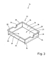
- the Fig. 3 shows the ink fountain 14 according to the invention with an insert 22 disposed therein for receiving the ink for the printing machine 10 in an enlarged view.
- the insert 22 can be inserted into the outer container 16 and easily removed after use. After complete drying of any color residues, the insert can be properly disposed of and recycled. A complex cleaning of the ink fountain 14 is eliminated. Furthermore, there is a conservation of environmental resources, because no cleaning rags, cleaning agents, solvents for cleaning are required.
- the insert 22 has a bottom 23 and side walls 24 extending from the bottom 23 for forming an interior 25. Deviating from the representations in the Fig. 3 and 4 for example, the insert 22 may have slightly obliquely directed sidewalls 24 that are slightly divergent from the bottom 23.
- the upper edges 26 of the insert 22 form a peripheral edge 27 around a preferably full-surface opening 28 of the insert 22.
- the edge 27 preferably has a circumferential collar 29.
- the collar 29 may be arranged in sections or continuously on the edge 27.
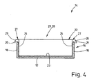
- the collar 29 of the rim 27 on the one hand stabilizes the insert 22 mechanically and on the other facilitates the removal of the insert 22 from the outer container 16. Furthermore, the collar 29 prevents color from getting between the insert 22 and the outer container 16. How out Fig.
- the insert 22 is formed corresponding to the interior of the outer container 16, such that the insert 22 with small gaps follows the contour of the interior of the outer container 16 or partially rests on the ink fountain 14 inside.
- the insert 22 hardly reduces the volume available for the ink in the ink fountain 14.
- the insert needs 22 due to the almost full-scale investment on the bottom 17 of the outer container 16 and thereby conditional support to have only a small material thickness, whereby the amount of waste is further reduced.
- the Fig. 4 shows the edge 27 with the collar 29 is not on the edge 20 of the outer container 16, but extends at a distance approximately parallel to this.
- the bottom 23 of the insert 22 is preferably on the entire surface of the bottom 17 of the container 16.
- the collar 29 of the edge 27 of the insert 22 may alternatively but also over the entire surface or partially rest on the edge 20 of the outer container 16, wherein the bottom 23 of the insert 22 may be formed such that it does not or only 17 the bottom 17 of the outer container partially touched.
- the insert 22 is "hooked" into the outer container.
- the edge 27 of the insert 22 is mechanically better supported, because this at least partially rests on the edge 20 of the outer container 16.
- the collar 29 of the peripheral edge 27 of the insert 22 can also be formed such that it the edge 20 of the outer container 16, as in Fig. 4 represented, embraces.
- the collar 29 has an approximately U-shaped cross section, which is open at the bottom.
- the collar 29 thereby forms a kind of beading of the edge 20 of the container 16.
- the mechanical stability of the rim 27 is further increased, ensures a tight fit of the insert 22 in the outer container 16 and at the same time improves the removability of the insert 22.
- additional reinforcing elements in the region of the bottom 23 and / or the side walls 24 of the insert 22, such as beads or shapes, can be provided. Such reinforcing elements are for clarity in the Fig. 4 not shown in detail.
- Fig. 4 it is possible in the Fig. 4 not shown, provide additional fastening means, for example in the region of the peripheral edge 27 of the insert 22 and the edge 20 of the outer container 16 to prevent accidental lifting of the insert 22 in the outer container 16 during operation of the printing press 10.
- the Fig. 3 shows approximately semicircular recesses in opposite (narrow) side walls 18 of the ink fountain 14.
- the recesses extend from the upper edge 20 of the ink fountain 14.
- the insert 22 is formed corresponding to the recesses in the ink fountain 14.
- the trained as a bead collar 29 of the insert 22 preferably also extends over the course of the recesses, so that the recesses are surrounded by the collar 29 and the edges of the recesses in the ink fountain 14 from this associated region of the collar 29 are embraced approximately U-shaped as is the case in the remaining regions of the collar 29.
- the wall thickness of the insert 22 is up to 1 mm, preferably between 0.3 mm and 0.8 mm.
- the insert 22 is preferably made by deep drawing a thermoplastic material in a known manner. As a result, a good adaptability of the insert 22 is given to the contour of the interiors of different color boxes 14 of printing presses.
- thermoplastic material for the manufacture of the insert 22 for example, polyethylene terephthalate (PET), polyvinyl chloride (PVC), polypropylene (PP) and polyethylene (PE) into consideration. Due to the high chemical resistance of these plastic materials, it is not necessary to use costly, corrosion-resistant materials such as stainless steel for the manufacture of the outer container 16 of the ink fountain 14 of the printing press 10, resulting in further savings.
- the insert 22 can also be made of other plastic materials, such as thermosets, silicones or any mixtures of thermoplastic and / or thermosetting plastic materials. It is also conceivable to use fiber-reinforced plastic materials in order to possibly increase the stability of the insert 22.
- the insert 22 Since the paint is in the insert 22, which is arranged in the ink fountain 14, the actual ink fountain 14 comes with no color in touch, so it stays clean. Color is only in use 22.
- the insert 22 In order to fill the ink fountain 14 of the color, in particular printing ink, the insert 22 is first inserted into the still empty ink fountain 14 and then filled into the insert 22, the color. But it is also conceivable to use the insert 22 together with the already filled in color in the ink fountain 14. It may be intended to open the mouth with paint filled insert 22 to close, for example, by a sealing foil, which is removed after insertion of the insert 22 in the ink fountain 14 and thereby releases the upper full-surface opening of the insert 22.
- the insert 22 thus also serves to dispose of the color.
- the paint is dried or cured prior to final disposal in the insert 22.
- the curing of color which is dried by ultraviolet light, is carried out by a brief irradiation of the color or the color remainder with ultraviolet rays, which can be done for example in a drying cabinet. After the paint has cured, it forms a solid unit with the insert 22, which as a whole can be disposed of.
Landscapes
- Printing Methods (AREA)
- Inking, Control Or Cleaning Of Printing Machines (AREA)
- Auxiliary Devices For And Details Of Packaging Control (AREA)
- Cartons (AREA)
- Impression-Transfer Materials And Handling Thereof (AREA)
Claims (6)
- Bac à encre (14) pour une imprimante (10), notamment une imprimante rotative, comprenant un récipient extérieur (16), qui présente un fond (17), des parois latérales (18) partant du fond (17) pour former un espace interne, et une ouverture (21) entourée par les arêtes supérieures (19) des parois latérales (18), les arêtes supérieures (19) des parois latérales (18) formant un bord périphérique (20) de l'ouverture (21), et au moins un insert (22) pour recevoir l'encre étant disposé dans le bac à encre (14), lequel présente un fond (23) ainsi que des parois latérales (24) partant du fond (23) pour former un espace interne (25) et une ouverture de grande surface (28) entourée par les arêtes supérieures (26) des parois latérales (18), qui présente un bord périphérique (27) formé par les arêtes supérieures (26), caractérisé en ce que le bord (27) de l'insert (22) présente un collet périphérique (29), qui est réalisé de manière saillante vers l'extérieur, de telle sorte que le collet (29) recouvre au moins en partie le bord (20) du récipient extérieur (16) et en ce que le fond (23) de l'insert (22) repose sur toute sa surface sur le fond (17) du récipient extérieur (16), le collet (29) ne reposant pas sur le bord (20) du récipient extérieur (16).
- Bac à encre (14) selon la revendication 1, caractérisé en ce que l'insert (22) est adapté au contour de l'espace interne du récipient extérieur (16), en ce que le contour extérieur de l'insert (22) correspond à l'espace interne du récipient extérieur (16).
- Bac à encre (14) selon la revendication 1 ou 2, caractérisé en ce que le récipient extérieur (16) et/ou l'insert (22) présentent des moyens de fixation pour la fixation de l'insert (22) dans le récipient extérieur (16).
- Bac à encre (14) selon l'une quelconque des revendications précédentes, caractérisé en ce que l'insert (22) est formé de manière étanche aux liquides et résistante à l'encre, de préférence l'insert (22) est formé d'un matériau en plastique emboutissable, avec une faible épaisseur de matériau, l'insert (22) pouvant en particulier être replié après avoir été ressorti du récipient extérieur (16).
- Bac à encre (14) selon l'une quelconque des revendications précédentes, caractérisé en ce que l'insert (22) présente, dans la région du fond (23) et/ou des parois latérales (24), des éléments de renforcement.
- Imprimante (10), notamment imprimante rotative, comprenant au moins un bac à encre (14), caractérisée en ce que le bac à encre (14) est réalisé selon au moins l'une quelconque des revendications 1 à 5.
Applications Claiming Priority (2)
| Application Number | Priority Date | Filing Date | Title |
|---|---|---|---|
| DE20204841U DE20204841U1 (de) | 2002-03-26 | 2002-03-26 | Farbkasten für eine Druckmaschine und Druckmaschine |
| DE20204841U | 2002-03-26 |
Publications (3)
| Publication Number | Publication Date |
|---|---|
| EP1348552A1 EP1348552A1 (fr) | 2003-10-01 |
| EP1348552A8 EP1348552A8 (fr) | 2004-04-28 |
| EP1348552B1 true EP1348552B1 (fr) | 2010-09-15 |
Family
ID=7969423
Family Applications (1)
| Application Number | Title | Priority Date | Filing Date |
|---|---|---|---|
| EP03006916A Expired - Lifetime EP1348552B1 (fr) | 2002-03-26 | 2003-03-26 | Pièce de rechange dans un bac à encre d'une machine à imprimer |
Country Status (3)
| Country | Link |
|---|---|
| EP (1) | EP1348552B1 (fr) |
| AT (1) | ATE481243T1 (fr) |
| DE (2) | DE20204841U1 (fr) |
Families Citing this family (2)
| Publication number | Priority date | Publication date | Assignee | Title |
|---|---|---|---|---|
| FR2962683B1 (fr) * | 2010-07-16 | 2013-11-08 | Patrick Daigneau | Dispositif de revetement amovible plastique pour encrier de machine d'imprimerie |
| US12220904B1 (en) * | 2023-09-12 | 2025-02-11 | Eastman Kodak Company | Inking system with segmented fountain roller |
Family Cites Families (13)
| Publication number | Priority date | Publication date | Assignee | Title |
|---|---|---|---|---|
| US512562A (en) * | 1894-01-09 | Ink-fountain | ||
| US457223A (en) | 1891-08-04 | Washing-machine | ||
| DE98025C (fr) | ||||
| GB1220934A (en) * | 1967-02-28 | 1971-01-27 | Dick Co Ab | Improvements relating to printing and duplicating |
| DE8813883U1 (de) | 1988-11-05 | 1988-12-22 | Vural, Cetin, 8058 Erding | Farbkasten-Einlage |
| DE4027377A1 (de) | 1990-08-30 | 1992-03-12 | Man Miller Druckmasch | Farbkastenanordnung einer druckmaschine |
| EP0508031B1 (fr) * | 1991-04-10 | 1994-08-31 | Sge Ag | Bac d'encrage pour une machine d'impression rotative |
| DE9113480U1 (de) | 1991-10-30 | 1992-01-02 | Heidelberger Druckmaschinen Ag, 6900 Heidelberg | Farbkasten für Druckmaschinen |
| DE4315595C2 (de) | 1993-05-11 | 1995-02-16 | Roland Man Druckmasch | Einsatz für Keilfarbkästen von Druckmaschinen |
| FR2726220B1 (fr) * | 1994-10-31 | 1997-01-17 | Heidelberg Harris Sa | Dispositif d'encrage pour une rotative d'impression |
| DE19640775A1 (de) * | 1996-10-02 | 1998-04-09 | Roland Man Druckmasch | Einsatz für einen Keilfarbkasten von Druckmaschinen |
| DE19826817A1 (de) | 1998-06-16 | 1999-12-23 | Koenig & Bauer Ag | Keilfarbkasten |
| CA2299890C (fr) * | 1999-08-19 | 2004-08-10 | Mitsubishi Heavy Industries, Ltd. | Appareil fournisseur d'encre |
-
2002
- 2002-03-26 DE DE20204841U patent/DE20204841U1/de not_active Expired - Lifetime
-
2003
- 2003-03-26 DE DE50313085T patent/DE50313085D1/de not_active Expired - Lifetime
- 2003-03-26 EP EP03006916A patent/EP1348552B1/fr not_active Expired - Lifetime
- 2003-03-26 AT AT03006916T patent/ATE481243T1/de active
Also Published As
| Publication number | Publication date |
|---|---|
| ATE481243T1 (de) | 2010-10-15 |
| DE20204841U1 (de) | 2002-09-05 |
| EP1348552A8 (fr) | 2004-04-28 |
| EP1348552A1 (fr) | 2003-10-01 |
| DE50313085D1 (de) | 2010-10-28 |
Similar Documents
| Publication | Publication Date | Title |
|---|---|---|
| DE3405105C1 (de) | OElbehaelter einer Kunststoff-Spritzgiessmaschine mit einem Luftfilter an einer Druckausgleichsoeffnung | |
| EP1302315B1 (fr) | Joint d'étanchéité d'une chambre de racle | |
| DE1604653B2 (de) | Hohlkoerper aus kunststoff sowie verfahren und vorrichtung zu dessen herstellung | |
| EP0386568A1 (fr) | Poubelle contenant un système de ventilation | |
| DE1925853A1 (de) | Behaelter | |
| AT512968A1 (de) | Stempel, insbesondere Rund-Stempel | |
| EP1348552B1 (fr) | Pièce de rechange dans un bac à encre d'une machine à imprimer | |
| EP4144658B1 (fr) | Seau doté d'une enveloppe intérieure et emballage | |
| EP3106035B1 (fr) | Corbeille de réception pour un dispositif de levage et procédé de chargement d'une machine de traitement de produits alimentaires | |
| EP0943583A1 (fr) | Procédé et dispositif pour la distribution de matériau visqueux | |
| EP3218278B1 (fr) | Récipient à canal de ventilation | |
| EP3142937B1 (fr) | Récipient à parois fermées | |
| EP1777174B1 (fr) | Poubelle en matière plastique | |
| DE102004060709A1 (de) | Einspülanordung mit Wasservorlauf für eine Waschmaschine | |
| DE102007055163A1 (de) | Tintenpatrone, insbesondere für einen Tintenstrahldrucker | |
| WO2002016137A1 (fr) | Racle de compartiment | |
| DE19836308A1 (de) | Minimüllpresse | |
| EP0045871B1 (fr) | Boîte pour rouleau encreur | |
| DE9306265U1 (de) | Müllbehälter | |
| EP2049337B1 (fr) | Dispositif de nettoyage de surfaces de cylindres d'impression | |
| DE8318804U1 (de) | Formeinrichtung zum herstellen von betonformteilen | |
| DE2317594C3 (de) | Käseform zum Herstellen von Käse mit einer dichten Käserinde, insbesondere zum Herstellen von gepreßtem Käse | |
| DE102023110435A1 (de) | Verfahren und vorrichtung zur herstellung eines faserformkörpers | |
| EP4543598A1 (fr) | Système de liaison d'un récipient à un dispositif de distribution, récipient et dispositif de distribution | |
| EP4566966A1 (fr) | Couvercle doté d'un couvercle en feuille, seau et emballage |
Legal Events
| Date | Code | Title | Description |
|---|---|---|---|
| PUAI | Public reference made under article 153(3) epc to a published international application that has entered the european phase |
Free format text: ORIGINAL CODE: 0009012 |
|
| AK | Designated contracting states |
Kind code of ref document: A1 Designated state(s): AT BE BG CH CY CZ DE DK EE ES FI FR GB GR HU IE IT LI LU MC NL PT RO SE SI SK TR |
|
| AX | Request for extension of the european patent |
Extension state: AL LT LV MK |
|
| RIN1 | Information on inventor provided before grant (corrected) |
Inventor name: GRAMSCH, MATHIAS |
|
| RAP1 | Party data changed (applicant data changed or rights of an application transferred) |
Owner name: GRAMSCH, MATHIAS Owner name: MENDRIKS, CLAUS |
|
| RIN1 | Information on inventor provided before grant (corrected) |
Inventor name: MENDRIKS, CLAUS Inventor name: GRAMSCH, MATHIAS |
|
| 17P | Request for examination filed |
Effective date: 20040331 |
|
| AKX | Designation fees paid |
Designated state(s): AT BE BG CH CY CZ DE DK EE ES FI FR GB GR HU IE IT LI LU MC NL PT RO SE SI SK TR |
|
| 17Q | First examination report despatched |
Effective date: 20060302 |
|
| GRAP | Despatch of communication of intention to grant a patent |
Free format text: ORIGINAL CODE: EPIDOSNIGR1 |
|
| GRAS | Grant fee paid |
Free format text: ORIGINAL CODE: EPIDOSNIGR3 |
|
| GRAA | (expected) grant |
Free format text: ORIGINAL CODE: 0009210 |
|
| AK | Designated contracting states |
Kind code of ref document: B1 Designated state(s): AT BE BG CH CY CZ DE DK EE ES FI FR GB GR HU IE IT LI LU MC NL PT RO SE SI SK TR |
|
| REG | Reference to a national code |
Ref country code: GB Ref legal event code: FG4D Free format text: NOT ENGLISH Ref country code: CH Ref legal event code: EP |
|
| REG | Reference to a national code |
Ref country code: IE Ref legal event code: FG4D Free format text: LANGUAGE OF EP DOCUMENT: GERMAN |
|
| REF | Corresponds to: |
Ref document number: 50313085 Country of ref document: DE Date of ref document: 20101028 Kind code of ref document: P |
|
| REG | Reference to a national code |
Ref country code: NL Ref legal event code: VDEP Effective date: 20100915 |
|
| PG25 | Lapsed in a contracting state [announced via postgrant information from national office to epo] |
Ref country code: FI Free format text: LAPSE BECAUSE OF FAILURE TO SUBMIT A TRANSLATION OF THE DESCRIPTION OR TO PAY THE FEE WITHIN THE PRESCRIBED TIME-LIMIT Effective date: 20100915 |
|
| PG25 | Lapsed in a contracting state [announced via postgrant information from national office to epo] |
Ref country code: SI Free format text: LAPSE BECAUSE OF FAILURE TO SUBMIT A TRANSLATION OF THE DESCRIPTION OR TO PAY THE FEE WITHIN THE PRESCRIBED TIME-LIMIT Effective date: 20100915 Ref country code: CY Free format text: LAPSE BECAUSE OF FAILURE TO SUBMIT A TRANSLATION OF THE DESCRIPTION OR TO PAY THE FEE WITHIN THE PRESCRIBED TIME-LIMIT Effective date: 20100915 |
|
| PG25 | Lapsed in a contracting state [announced via postgrant information from national office to epo] |
Ref country code: GR Free format text: LAPSE BECAUSE OF FAILURE TO SUBMIT A TRANSLATION OF THE DESCRIPTION OR TO PAY THE FEE WITHIN THE PRESCRIBED TIME-LIMIT Effective date: 20101216 Ref country code: SE Free format text: LAPSE BECAUSE OF FAILURE TO SUBMIT A TRANSLATION OF THE DESCRIPTION OR TO PAY THE FEE WITHIN THE PRESCRIBED TIME-LIMIT Effective date: 20100915 |
|
| REG | Reference to a national code |
Ref country code: IE Ref legal event code: FD4D |
|
| PG25 | Lapsed in a contracting state [announced via postgrant information from national office to epo] |
Ref country code: IE Free format text: LAPSE BECAUSE OF FAILURE TO SUBMIT A TRANSLATION OF THE DESCRIPTION OR TO PAY THE FEE WITHIN THE PRESCRIBED TIME-LIMIT Effective date: 20100915 |
|
| PG25 | Lapsed in a contracting state [announced via postgrant information from national office to epo] |
Ref country code: PT Free format text: LAPSE BECAUSE OF FAILURE TO SUBMIT A TRANSLATION OF THE DESCRIPTION OR TO PAY THE FEE WITHIN THE PRESCRIBED TIME-LIMIT Effective date: 20110117 Ref country code: NL Free format text: LAPSE BECAUSE OF FAILURE TO SUBMIT A TRANSLATION OF THE DESCRIPTION OR TO PAY THE FEE WITHIN THE PRESCRIBED TIME-LIMIT Effective date: 20100915 Ref country code: CZ Free format text: LAPSE BECAUSE OF FAILURE TO SUBMIT A TRANSLATION OF THE DESCRIPTION OR TO PAY THE FEE WITHIN THE PRESCRIBED TIME-LIMIT Effective date: 20100915 Ref country code: EE Free format text: LAPSE BECAUSE OF FAILURE TO SUBMIT A TRANSLATION OF THE DESCRIPTION OR TO PAY THE FEE WITHIN THE PRESCRIBED TIME-LIMIT Effective date: 20100915 Ref country code: SK Free format text: LAPSE BECAUSE OF FAILURE TO SUBMIT A TRANSLATION OF THE DESCRIPTION OR TO PAY THE FEE WITHIN THE PRESCRIBED TIME-LIMIT Effective date: 20100915 Ref country code: IT Free format text: LAPSE BECAUSE OF FAILURE TO SUBMIT A TRANSLATION OF THE DESCRIPTION OR TO PAY THE FEE WITHIN THE PRESCRIBED TIME-LIMIT Effective date: 20100915 Ref country code: RO Free format text: LAPSE BECAUSE OF FAILURE TO SUBMIT A TRANSLATION OF THE DESCRIPTION OR TO PAY THE FEE WITHIN THE PRESCRIBED TIME-LIMIT Effective date: 20100915 |
|
| PG25 | Lapsed in a contracting state [announced via postgrant information from national office to epo] |
Ref country code: ES Free format text: LAPSE BECAUSE OF FAILURE TO SUBMIT A TRANSLATION OF THE DESCRIPTION OR TO PAY THE FEE WITHIN THE PRESCRIBED TIME-LIMIT Effective date: 20101226 |
|
| PLBE | No opposition filed within time limit |
Free format text: ORIGINAL CODE: 0009261 |
|
| STAA | Information on the status of an ep patent application or granted ep patent |
Free format text: STATUS: NO OPPOSITION FILED WITHIN TIME LIMIT |
|
| 26N | No opposition filed |
Effective date: 20110616 |
|
| PG25 | Lapsed in a contracting state [announced via postgrant information from national office to epo] |
Ref country code: DK Free format text: LAPSE BECAUSE OF FAILURE TO SUBMIT A TRANSLATION OF THE DESCRIPTION OR TO PAY THE FEE WITHIN THE PRESCRIBED TIME-LIMIT Effective date: 20100915 |
|
| BERE | Be: lapsed |
Owner name: MENDRIKS, CLAUS Effective date: 20110331 Owner name: GRAMSCH, MATHIAS Effective date: 20110331 |
|
| REG | Reference to a national code |
Ref country code: DE Ref legal event code: R097 Ref document number: 50313085 Country of ref document: DE Effective date: 20110616 |
|
| PG25 | Lapsed in a contracting state [announced via postgrant information from national office to epo] |
Ref country code: MC Free format text: LAPSE BECAUSE OF NON-PAYMENT OF DUE FEES Effective date: 20110331 |
|
| REG | Reference to a national code |
Ref country code: CH Ref legal event code: PL |
|
| GBPC | Gb: european patent ceased through non-payment of renewal fee |
Effective date: 20110326 |
|
| REG | Reference to a national code |
Ref country code: FR Ref legal event code: ST Effective date: 20111130 |
|
| PG25 | Lapsed in a contracting state [announced via postgrant information from national office to epo] |
Ref country code: BE Free format text: LAPSE BECAUSE OF NON-PAYMENT OF DUE FEES Effective date: 20110331 |
|
| PG25 | Lapsed in a contracting state [announced via postgrant information from national office to epo] |
Ref country code: LI Free format text: LAPSE BECAUSE OF NON-PAYMENT OF DUE FEES Effective date: 20110331 Ref country code: CH Free format text: LAPSE BECAUSE OF NON-PAYMENT OF DUE FEES Effective date: 20110331 Ref country code: DE Free format text: LAPSE BECAUSE OF NON-PAYMENT OF DUE FEES Effective date: 20111001 Ref country code: FR Free format text: LAPSE BECAUSE OF NON-PAYMENT OF DUE FEES Effective date: 20110331 |
|
| REG | Reference to a national code |
Ref country code: DE Ref legal event code: R119 Ref document number: 50313085 Country of ref document: DE Effective date: 20111001 |
|
| PG25 | Lapsed in a contracting state [announced via postgrant information from national office to epo] |
Ref country code: GB Free format text: LAPSE BECAUSE OF NON-PAYMENT OF DUE FEES Effective date: 20110326 |
|
| REG | Reference to a national code |
Ref country code: AT Ref legal event code: MM01 Ref document number: 481243 Country of ref document: AT Kind code of ref document: T Effective date: 20110326 |
|
| PG25 | Lapsed in a contracting state [announced via postgrant information from national office to epo] |
Ref country code: AT Free format text: LAPSE BECAUSE OF NON-PAYMENT OF DUE FEES Effective date: 20110326 |
|
| PG25 | Lapsed in a contracting state [announced via postgrant information from national office to epo] |
Ref country code: LU Free format text: LAPSE BECAUSE OF NON-PAYMENT OF DUE FEES Effective date: 20110326 |
|
| PG25 | Lapsed in a contracting state [announced via postgrant information from national office to epo] |
Ref country code: TR Free format text: LAPSE BECAUSE OF FAILURE TO SUBMIT A TRANSLATION OF THE DESCRIPTION OR TO PAY THE FEE WITHIN THE PRESCRIBED TIME-LIMIT Effective date: 20100915 Ref country code: BG Free format text: LAPSE BECAUSE OF FAILURE TO SUBMIT A TRANSLATION OF THE DESCRIPTION OR TO PAY THE FEE WITHIN THE PRESCRIBED TIME-LIMIT Effective date: 20101215 |
|
| PG25 | Lapsed in a contracting state [announced via postgrant information from national office to epo] |
Ref country code: HU Free format text: LAPSE BECAUSE OF FAILURE TO SUBMIT A TRANSLATION OF THE DESCRIPTION OR TO PAY THE FEE WITHIN THE PRESCRIBED TIME-LIMIT Effective date: 20100915 |