EP1348528A2 - Führungseinsatz für eine Kernbohrkrone - Google Patents
Führungseinsatz für eine Kernbohrkrone Download PDFInfo
- Publication number
- EP1348528A2 EP1348528A2 EP03405177A EP03405177A EP1348528A2 EP 1348528 A2 EP1348528 A2 EP 1348528A2 EP 03405177 A EP03405177 A EP 03405177A EP 03405177 A EP03405177 A EP 03405177A EP 1348528 A2 EP1348528 A2 EP 1348528A2
- Authority
- EP
- European Patent Office
- Prior art keywords
- axially
- guide
- guide insert
- insert according
- core
- Prior art date
- Legal status (The legal status is an assumption and is not a legal conclusion. Google has not performed a legal analysis and makes no representation as to the accuracy of the status listed.)
- Granted
Links
Images
Classifications
-
- B—PERFORMING OPERATIONS; TRANSPORTING
- B28—WORKING CEMENT, CLAY, OR STONE
- B28D—WORKING STONE OR STONE-LIKE MATERIALS
- B28D1/00—Working stone or stone-like materials, e.g. brick, concrete or glass, not provided for elsewhere; Machines, devices, tools therefor
- B28D1/02—Working stone or stone-like materials, e.g. brick, concrete or glass, not provided for elsewhere; Machines, devices, tools therefor by sawing
- B28D1/04—Working stone or stone-like materials, e.g. brick, concrete or glass, not provided for elsewhere; Machines, devices, tools therefor by sawing with circular or cylindrical saw-blades or saw-discs
- B28D1/041—Working stone or stone-like materials, e.g. brick, concrete or glass, not provided for elsewhere; Machines, devices, tools therefor by sawing with circular or cylindrical saw-blades or saw-discs with cylinder saws, e.g. trepanning; saw cylinders, e.g. having their cutting rim equipped with abrasive particles
-
- B—PERFORMING OPERATIONS; TRANSPORTING
- B23—MACHINE TOOLS; METAL-WORKING NOT OTHERWISE PROVIDED FOR
- B23B—TURNING; BORING
- B23B51/00—Tools for drilling machines
- B23B51/04—Drills for trepanning
- B23B51/0426—Drills for trepanning with centering devices
Definitions
- the invention relates to a removable guide insert after drilling for a Core drill bit, such as a countersink for concrete and masonry.
- Such core bits have cutting inserts distributed in the form of geometrically undefined cutting edges with diamond-studded matrix or geometric defined cutting edges with polycrystalline diamonds.
- a guide insert for core bits has a through Crown base that can be submerged and axially pre-tensioned for guidance use Center point on by inserting the guide insert into the hollow shaft of the core bit is used.
- Center point on by inserting the guide insert into the hollow shaft of the core bit is used.
- the object of the invention is to implement a management insert for a Core drill bit, which enables precise drilling without unnecessary wearing parts.
- a guide insert for a core bit is at least partially axially on an inner wall of the core bit and protrudes with cantilevers between the one end of a drill pipe of the core bit, several Cutting inserts radially, one at least partially axially over the cutting inserts protruding coaxial centering means is present, which is shorter than the axial length formed of the drill pipe, axially resiliently biased within the guide insert as well as being axially movable.
- the centering means is advantageously axially resiliently biased by a spiral compression spring, which can be arranged in a space-saving manner coaxially between the centering means and the guide insert.
- the centering means is advantageous as a bolt, which is further advantageously made of hardened steel exists, with an axially frontal, conical centering tip, whereby a Centering without unnecessary wearing parts, e.g. to create a guide hole he follows.
- the bolt on an axially opposite the centering tip is advantageous Guide shaft, radially tapered and stepped, making it an axial stop for the spiral compression spring is used.
- the bolt is advantageously arranged in a form-locked manner in the guide insert, whereby wear caused by relative rotation is avoided.
- the guide insert advantageously has a rotation behind the cutting inserts axially lockable undercut, which prevents the guide insert from falling out is secured.
- the guide insert advantageously has a coaxial on the inner wall of the core drill bit guided, sleeve-shaped insert, which is further advantageously made of plastic exists, whereby a technically simple production is possible, for example by injection molding.
- the insert advantageously has at least three on the circumference of the inner diameter of the assigned core drill bit, further advantageously uniformly, circumferentially spaced Guide surfaces, which extend at least partially axially, making it easier Way a coaxial guidance is made possible.
- the insert advantageously has circumferentially spaced, radially multiple discrete offset guide surfaces, creating a single guide insert for core bits several different diameters is suitable.
- the guide surfaces are advantageously directly adjacent to the radial projections assigned, whereby the absorption of the transverse forces directly on the front of the Drilling tube with the cutting inserts.
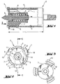
- a guide insert 1 for a core drill bit 2 shown in longitudinal section partially guided axially on an inner wall 3 of the core bit 2, protrudes between them one end of a drill pipe 4 of the core drill bit 2, several Cutting inserts 5 radially and abuts axially on the end face of the drill pipe 4.
- Coaxial centering means 6 projecting partially axially beyond the cutting inserts 5 is as Bolt with an axially frontal, conical centering point with a radially tapered, stepped leadership training.
- the centering means 6 is shorter than the axial one Length L of the drill pipe 4 formed compared to a sleeve-shaped insert 7 one, coaxial between the guide shaft of the centering means 6 and the insert means 7 arranged, coil compression spring 8 axially resiliently biased and axially limited movement.
- the insert 7 has on the circumference of the inner diameter of the assigned Core drill bit 2 on circumferentially spaced guide surfaces 9, which are partially extend axially and are assigned directly adjacent radial projections 10.
- the guide insert 1 shown in front view, with its three radial ones Overhangs 10 in the gaps between the three cutting inserts 5 of the core drill bit 2 suitably inserted on the end face and each with an axially lockable web 11 by twisting locked behind the cutting inserts 5.
- the bolt 6 is through a hexagonal profile Insert 7 non-rotatably, limited axially movable out.
- the insert means 7 shown in the rear view is extensive spaced, radially double discretely offset guide surfaces 9, 9 ', which are each partially extend axially and directly the three pairs in common radial Overhangs 10 are assigned adjacent.
- Such a variant for another The number of different diameters, for example three or four, is accordingly triple or to execute guide surfaces 9 offset radially and four times.
Landscapes
- Engineering & Computer Science (AREA)
- Mechanical Engineering (AREA)
- Mining & Mineral Resources (AREA)
- Processing Of Stones Or Stones Resemblance Materials (AREA)
- Drilling Tools (AREA)
- Molds, Cores, And Manufacturing Methods Thereof (AREA)
- Road Signs Or Road Markings (AREA)
- Excavating Of Shafts Or Tunnels (AREA)
- Earth Drilling (AREA)
Abstract
Description
Claims (10)
- Führungseinsatz für eine Kernbohrkrone (2), welcher zumindest teilweise axial an einer Innenwand (3) der Kernbohrkrone (2) geführt ist und der zwischen den, an einer Stirnseite eines Bohrrohres (4) der Kernbohrkrone (2) vorhandenen, mehreren Schneideinsätzen (5) mit Auskragungen (10) radial auskragt, wobei ein zumindest teilweise axial über die Schneideinsätze (5) überstehendes, koaxiales Zentriermittel (6) vorhanden ist, dadurch gekennzeichnet, dass das Zentriermittel (6) kürzer als die axiale Länge (L) des Bohrrohres (4) ausgebildet, innerhalb des Führungseinsatzes axial federnd vorgespannt, sowie axial begrenzt beweglich ist.
- Führungseinsatz nach Anspruch 1, dadurch gekennzeichnet, dass das Zentriermittel (6) mit einer Spiraldruckfeder (8) axial federnd vorgespannt ist.
- Führungseinsatz nach Anspruch 1 oder 2, dadurch gekennzeichnet, dass das Zentriermittel (6) als Bolzen, welcher optional aus gehärtetem Stahl besteht, mit einer axial stirnseitigen, kegelförmigen Zentrierspitze ausgeführt ist.
- Führungseinsatz nach Anspruch 3, dadurch gekennzeichnet, dass der Bolzen an einem, der Zentrierspitze axial gegenüberliegenden, Führungsschaft, radial verjüngt und gestuft abgesetzt ist.
- Führungseinsatz nach Anspruch 3 oder 4, dadurch gekennzeichnet, dass der Bolzen formschlüssig drehfest im Führungseinsatz angeordnet ist.
- Führungseinsatz nach einem der vorherigen Ansprüche, dadurch gekennzeichnet, dass ein durch Verdrehung hinter die Schneideinsätze (5) axial arretierbarer Steg (11) vorhanden ist.
- Führungseinsatz nach einem der vorherigen Ansprüche, dadurch gekennzeichnet, dass ein an der Innenwand (3) der Kernbohrkrone (2) koaxial geführtes, hülsenförmiges Einsatzmittel (7) vorhanden ist, welches optional aus Kunststoff besteht.
- Führungseinsatz nach Anspruch 7, dadurch gekennzeichnet, dass das Einsatzmittel (7) zumindest drei am Umfang des Innendurchmessers der zugeordneten Kernbohrkrone (2), optional gleichmässig, umfänglich beabstandete Führungsflächen (9, 9') aufweist, welche sich zumindest teilweise axial erstrecken.
- Führungseinsatz nach Anspruch 8, dadurch gekennzeichnet, dass das Einsatzmittel (7) jeweils umfänglich beabstandete, radial mehrfach diskret versetzte Führungsflächen (9, 9') aufweist.
- Führungseinsatz nach Anspruch 8 oder 9, dadurch gekennzeichnet, dass die Führungsflächen (9, 9') unmittelbar den radialen Auskragungen (10) benachbart zugeordnet sind.
Applications Claiming Priority (2)
| Application Number | Priority Date | Filing Date | Title |
|---|---|---|---|
| DE10213217 | 2002-03-25 | ||
| DE10213217A DE10213217A1 (de) | 2002-03-25 | 2002-03-25 | Führungseinsatz für eine Kernbohrkrone |
Publications (3)
| Publication Number | Publication Date |
|---|---|
| EP1348528A2 true EP1348528A2 (de) | 2003-10-01 |
| EP1348528A3 EP1348528A3 (de) | 2004-04-28 |
| EP1348528B1 EP1348528B1 (de) | 2006-03-22 |
Family
ID=27798167
Family Applications (1)
| Application Number | Title | Priority Date | Filing Date |
|---|---|---|---|
| EP03405177A Expired - Lifetime EP1348528B1 (de) | 2002-03-25 | 2003-03-14 | Führungseinsatz für eine Kernbohrkrone |
Country Status (8)
| Country | Link |
|---|---|
| US (1) | US20030213621A1 (de) |
| EP (1) | EP1348528B1 (de) |
| JP (1) | JP4795627B2 (de) |
| AT (1) | ATE320899T1 (de) |
| AU (1) | AU2003200745A1 (de) |
| DE (2) | DE10213217A1 (de) |
| DK (1) | DK1348528T3 (de) |
| ES (1) | ES2256702T3 (de) |
Cited By (5)
| Publication number | Priority date | Publication date | Assignee | Title |
|---|---|---|---|---|
| WO2009074776A1 (en) * | 2007-12-11 | 2009-06-18 | C4 Carbides Limited | Cutting apparatus |
| US8910360B1 (en) * | 2009-12-03 | 2014-12-16 | The Boeing Company | Floating insert removal tool |
| EP2340346A4 (de) * | 2008-10-09 | 2014-12-24 | Baker Hughes Inc | Bohrer mit einstellbarer axialauflage zur steuerung von torsionsschwankungen |
| US9915138B2 (en) | 2008-09-25 | 2018-03-13 | Baker Hughes, A Ge Company, Llc | Drill bit with hydraulically adjustable axial pad for controlling torsional fluctuations |
| CN112081530A (zh) * | 2020-10-20 | 2020-12-15 | 中国石油集团渤海钻探工程有限公司 | 一种带有缓冲机构的pdc钻头 |
Families Citing this family (74)
| Publication number | Priority date | Publication date | Assignee | Title |
|---|---|---|---|---|
| US7484576B2 (en) | 2006-03-23 | 2009-02-03 | Hall David R | Jack element in communication with an electric motor and or generator |
| US7419018B2 (en) | 2006-11-01 | 2008-09-02 | Hall David R | Cam assembly in a downhole component |
| US7360610B2 (en) * | 2005-11-21 | 2008-04-22 | Hall David R | Drill bit assembly for directional drilling |
| US7225886B1 (en) * | 2005-11-21 | 2007-06-05 | Hall David R | Drill bit assembly with an indenting member |
| US8408336B2 (en) | 2005-11-21 | 2013-04-02 | Schlumberger Technology Corporation | Flow guide actuation |
| US8360174B2 (en) | 2006-03-23 | 2013-01-29 | Schlumberger Technology Corporation | Lead the bit rotary steerable tool |
| US7600586B2 (en) | 2006-12-15 | 2009-10-13 | Hall David R | System for steering a drill string |
| US7624824B2 (en) * | 2005-12-22 | 2009-12-01 | Hall David R | Downhole hammer assembly |
| US7497279B2 (en) | 2005-11-21 | 2009-03-03 | Hall David R | Jack element adapted to rotate independent of a drill bit |
| US7424922B2 (en) | 2005-11-21 | 2008-09-16 | Hall David R | Rotary valve for a jack hammer |
| US7641002B2 (en) | 2005-11-21 | 2010-01-05 | Hall David R | Drill bit |
| US8297375B2 (en) | 2005-11-21 | 2012-10-30 | Schlumberger Technology Corporation | Downhole turbine |
| US7533737B2 (en) | 2005-11-21 | 2009-05-19 | Hall David R | Jet arrangement for a downhole drill bit |
| US7419016B2 (en) | 2006-03-23 | 2008-09-02 | Hall David R | Bi-center drill bit |
| US7571780B2 (en) | 2006-03-24 | 2009-08-11 | Hall David R | Jack element for a drill bit |
| US8522897B2 (en) | 2005-11-21 | 2013-09-03 | Schlumberger Technology Corporation | Lead the bit rotary steerable tool |
| US7753144B2 (en) | 2005-11-21 | 2010-07-13 | Schlumberger Technology Corporation | Drill bit with a retained jack element |
| US7559379B2 (en) | 2005-11-21 | 2009-07-14 | Hall David R | Downhole steering |
| US7591327B2 (en) | 2005-11-21 | 2009-09-22 | Hall David R | Drilling at a resonant frequency |
| US8316964B2 (en) | 2006-03-23 | 2012-11-27 | Schlumberger Technology Corporation | Drill bit transducer device |
| US7762353B2 (en) | 2006-03-23 | 2010-07-27 | Schlumberger Technology Corporation | Downhole valve mechanism |
| US8130117B2 (en) | 2006-03-23 | 2012-03-06 | Schlumberger Technology Corporation | Drill bit with an electrically isolated transmitter |
| US8528664B2 (en) | 2005-11-21 | 2013-09-10 | Schlumberger Technology Corporation | Downhole mechanism |
| US7617886B2 (en) | 2005-11-21 | 2009-11-17 | Hall David R | Fluid-actuated hammer bit |
| US8225883B2 (en) | 2005-11-21 | 2012-07-24 | Schlumberger Technology Corporation | Downhole percussive tool with alternating pressure differentials |
| US7549489B2 (en) | 2006-03-23 | 2009-06-23 | Hall David R | Jack element with a stop-off |
| US8297378B2 (en) | 2005-11-21 | 2012-10-30 | Schlumberger Technology Corporation | Turbine driven hammer that oscillates at a constant frequency |
| US7900720B2 (en) | 2006-01-18 | 2011-03-08 | Schlumberger Technology Corporation | Downhole drive shaft connection |
| US8011457B2 (en) | 2006-03-23 | 2011-09-06 | Schlumberger Technology Corporation | Downhole hammer assembly |
| USD620510S1 (en) | 2006-03-23 | 2010-07-27 | Schlumberger Technology Corporation | Drill bit |
| US7694756B2 (en) | 2006-03-23 | 2010-04-13 | Hall David R | Indenting member for a drill bit |
| US7661487B2 (en) | 2006-03-23 | 2010-02-16 | Hall David R | Downhole percussive tool with alternating pressure differentials |
| US8567532B2 (en) | 2006-08-11 | 2013-10-29 | Schlumberger Technology Corporation | Cutting element attached to downhole fixed bladed bit at a positive rake angle |
| US8616305B2 (en) | 2006-08-11 | 2013-12-31 | Schlumberger Technology Corporation | Fixed bladed bit that shifts weight between an indenter and cutting elements |
| US7637574B2 (en) | 2006-08-11 | 2009-12-29 | Hall David R | Pick assembly |
| US8714285B2 (en) | 2006-08-11 | 2014-05-06 | Schlumberger Technology Corporation | Method for drilling with a fixed bladed bit |
| US9051795B2 (en) | 2006-08-11 | 2015-06-09 | Schlumberger Technology Corporation | Downhole drill bit |
| US8622155B2 (en) | 2006-08-11 | 2014-01-07 | Schlumberger Technology Corporation | Pointed diamond working ends on a shear bit |
| US8122980B2 (en) | 2007-06-22 | 2012-02-28 | Schlumberger Technology Corporation | Rotary drag bit with pointed cutting elements |
| US8215420B2 (en) | 2006-08-11 | 2012-07-10 | Schlumberger Technology Corporation | Thermally stable pointed diamond with increased impact resistance |
| US8449040B2 (en) | 2006-08-11 | 2013-05-28 | David R. Hall | Shank for an attack tool |
| US20080035389A1 (en) | 2006-08-11 | 2008-02-14 | Hall David R | Roof Mining Drill Bit |
| US8240404B2 (en) | 2006-08-11 | 2012-08-14 | Hall David R | Roof bolt bit |
| US9316061B2 (en) | 2006-08-11 | 2016-04-19 | David R. Hall | High impact resistant degradation element |
| US7669674B2 (en) | 2006-08-11 | 2010-03-02 | Hall David R | Degradation assembly |
| US8590644B2 (en) | 2006-08-11 | 2013-11-26 | Schlumberger Technology Corporation | Downhole drill bit |
| US8596381B2 (en) * | 2006-08-11 | 2013-12-03 | David R. Hall | Sensor on a formation engaging member of a drill bit |
| US9145742B2 (en) | 2006-08-11 | 2015-09-29 | Schlumberger Technology Corporation | Pointed working ends on a drill bit |
| US7871133B2 (en) | 2006-08-11 | 2011-01-18 | Schlumberger Technology Corporation | Locking fixture |
| US7527110B2 (en) | 2006-10-13 | 2009-05-05 | Hall David R | Percussive drill bit |
| US8960337B2 (en) | 2006-10-26 | 2015-02-24 | Schlumberger Technology Corporation | High impact resistant tool with an apex width between a first and second transitions |
| US9068410B2 (en) | 2006-10-26 | 2015-06-30 | Schlumberger Technology Corporation | Dense diamond body |
| US7954401B2 (en) | 2006-10-27 | 2011-06-07 | Schlumberger Technology Corporation | Method of assembling a drill bit with a jack element |
| US7392857B1 (en) | 2007-01-03 | 2008-07-01 | Hall David R | Apparatus and method for vibrating a drill bit |
| USD674422S1 (en) | 2007-02-12 | 2013-01-15 | Hall David R | Drill bit with a pointed cutting element and a shearing cutting element |
| USD678368S1 (en) | 2007-02-12 | 2013-03-19 | David R. Hall | Drill bit with a pointed cutting element |
| US8839888B2 (en) | 2010-04-23 | 2014-09-23 | Schlumberger Technology Corporation | Tracking shearing cutters on a fixed bladed drill bit with pointed cutting elements |
| US7866416B2 (en) | 2007-06-04 | 2011-01-11 | Schlumberger Technology Corporation | Clutch for a jack element |
| US7721826B2 (en) | 2007-09-06 | 2010-05-25 | Schlumberger Technology Corporation | Downhole jack assembly sensor |
| US7967083B2 (en) | 2007-09-06 | 2011-06-28 | Schlumberger Technology Corporation | Sensor for determining a position of a jack element |
| US8540037B2 (en) | 2008-04-30 | 2013-09-24 | Schlumberger Technology Corporation | Layered polycrystalline diamond |
| US8701799B2 (en) | 2009-04-29 | 2014-04-22 | Schlumberger Technology Corporation | Drill bit cutter pocket restitution |
| US8550190B2 (en) | 2010-04-01 | 2013-10-08 | David R. Hall | Inner bit disposed within an outer bit |
| US8418784B2 (en) | 2010-05-11 | 2013-04-16 | David R. Hall | Central cutting region of a drilling head assembly |
| US9080387B2 (en) | 2010-08-03 | 2015-07-14 | Baker Hughes Incorporated | Directional wellbore control by pilot hole guidance |
| US8333254B2 (en) | 2010-10-01 | 2012-12-18 | Hall David R | Steering mechanism with a ring disposed about an outer diameter of a drill bit and method for drilling |
| US8820440B2 (en) | 2010-10-01 | 2014-09-02 | David R. Hall | Drill bit steering assembly |
| US9151120B2 (en) * | 2012-06-04 | 2015-10-06 | Baker Hughes Incorporated | Face stabilized downhole cutting tool |
| CN104110217A (zh) * | 2013-04-19 | 2014-10-22 | 苏州文鼎模具有限公司 | 一种导向钻头 |
| WO2015065896A1 (en) | 2013-11-01 | 2015-05-07 | Milwaukee Electric Tool Corporation | Pilot pin for drill press |
| US10046401B2 (en) * | 2013-11-05 | 2018-08-14 | Elber Gamboa Arias | Hole saw guide device |
| CN110814369B (zh) * | 2019-11-27 | 2021-04-02 | 无锡微尔逊流体控制技术有限公司 | 一种防偏离型孔内槽加工刀具组件 |
| CN112428415A (zh) * | 2020-11-23 | 2021-03-02 | 富强科技股份有限公司 | 无端板接桩器 |
| CN118669052A (zh) * | 2024-08-20 | 2024-09-20 | 中国石油大学(华东) | 一种具有地应力卸载功能的多阶梯pdc钻头及钻井方法 |
Family Cites Families (17)
| Publication number | Priority date | Publication date | Assignee | Title |
|---|---|---|---|---|
| US475559A (en) * | 1892-05-24 | Plug-cutter | ||
| GB122317A (en) * | 1918-03-08 | 1919-01-23 | Arthur Collier | Improvements in or relating to Bits and like Boring Tools. |
| GB170193A (en) * | 1920-10-02 | 1921-10-20 | James Edward Downing | Improvements in rotary cutters and holders for same |
| US3833073A (en) * | 1973-07-16 | 1974-09-03 | C Carver | Floor tap insert drill |
| US4129400A (en) * | 1975-11-26 | 1978-12-12 | Wozar Tiberius | Trepanning tool |
| US4090804A (en) * | 1977-02-04 | 1978-05-23 | Haley Ernest K | Circular drill with centering device |
| US4193721A (en) * | 1978-11-22 | 1980-03-18 | Hougen Everett D | Arbor for annular hole cutter |
| DD268599A3 (de) * | 1986-11-21 | 1989-06-07 | Bau U Montagekombinat Kohle Un | Bohrvorrichtung, insbesondere fuer kernbohrungen |
| US5316418A (en) * | 1992-09-21 | 1994-05-31 | Kabushiki Kaisha Miyanaga | Hole cutter |
| JP2598160Y2 (ja) * | 1992-10-23 | 1999-08-03 | 大見工業株式会社 | ホールカッター用のスターターセンタピン |
| JP2677948B2 (ja) * | 1993-07-12 | 1997-11-17 | 株式会社ミヤナガ | コアドリル |
| DE4420999C2 (de) * | 1994-06-17 | 2003-10-09 | Hilti Ag | Hohlbohrwerkzeug mit auswechselbarem Zentrierbohrer |
| DE4441275B4 (de) * | 1994-11-19 | 2004-03-25 | Robert Bosch Gmbh | Zentrierbohreinsatz für ein Hohlbohrwerkzeug |
| EP0799967B1 (de) * | 1996-04-01 | 2001-10-24 | Hawera Probst GmbH | Bohrkrone mit Zentrierbohrer |
| US6171032B1 (en) * | 1999-04-23 | 2001-01-09 | Visteon Global Technologies, Inc. | Mechanically actuated chip-less boring head for forming a hole in a workpiece |
| US6357972B1 (en) * | 2000-02-29 | 2002-03-19 | Daimlerchrysler Corporation | Tool and method for cutting holes in film |
| JP2003025130A (ja) * | 2001-07-19 | 2003-01-29 | Babcock Hitachi Kk | 大径深溝加工装置と大径深溝加工方法 |
-
2002
- 2002-03-25 DE DE10213217A patent/DE10213217A1/de not_active Withdrawn
-
2003
- 2003-02-28 AU AU2003200745A patent/AU2003200745A1/en not_active Abandoned
- 2003-03-14 DE DE50302734T patent/DE50302734D1/de not_active Expired - Lifetime
- 2003-03-14 DK DK03405177T patent/DK1348528T3/da active
- 2003-03-14 AT AT03405177T patent/ATE320899T1/de not_active IP Right Cessation
- 2003-03-14 ES ES03405177T patent/ES2256702T3/es not_active Expired - Lifetime
- 2003-03-14 EP EP03405177A patent/EP1348528B1/de not_active Expired - Lifetime
- 2003-03-19 JP JP2003075635A patent/JP4795627B2/ja not_active Expired - Fee Related
- 2003-03-25 US US10/400,095 patent/US20030213621A1/en not_active Abandoned
Cited By (7)
| Publication number | Priority date | Publication date | Assignee | Title |
|---|---|---|---|---|
| WO2009074776A1 (en) * | 2007-12-11 | 2009-06-18 | C4 Carbides Limited | Cutting apparatus |
| US8858133B2 (en) | 2007-12-11 | 2014-10-14 | C4 Carbides Limited | Cutting apparatus |
| US9915138B2 (en) | 2008-09-25 | 2018-03-13 | Baker Hughes, A Ge Company, Llc | Drill bit with hydraulically adjustable axial pad for controlling torsional fluctuations |
| US10001005B2 (en) | 2008-09-25 | 2018-06-19 | Baker Hughes, A Ge Company, Llc | Drill bit with hydraulically adjustable axial pad for controlling torsional fluctuations |
| EP2340346A4 (de) * | 2008-10-09 | 2014-12-24 | Baker Hughes Inc | Bohrer mit einstellbarer axialauflage zur steuerung von torsionsschwankungen |
| US8910360B1 (en) * | 2009-12-03 | 2014-12-16 | The Boeing Company | Floating insert removal tool |
| CN112081530A (zh) * | 2020-10-20 | 2020-12-15 | 中国石油集团渤海钻探工程有限公司 | 一种带有缓冲机构的pdc钻头 |
Also Published As
| Publication number | Publication date |
|---|---|
| ATE320899T1 (de) | 2006-04-15 |
| DE10213217A1 (de) | 2003-10-16 |
| ES2256702T3 (es) | 2006-07-16 |
| JP2003291135A (ja) | 2003-10-14 |
| AU2003200745A1 (en) | 2003-10-09 |
| EP1348528A3 (de) | 2004-04-28 |
| JP4795627B2 (ja) | 2011-10-19 |
| DE50302734D1 (de) | 2006-05-11 |
| US20030213621A1 (en) | 2003-11-20 |
| DK1348528T3 (da) | 2006-07-31 |
| EP1348528B1 (de) | 2006-03-22 |
Similar Documents
| Publication | Publication Date | Title |
|---|---|---|
| EP1348528B1 (de) | Führungseinsatz für eine Kernbohrkrone | |
| EP0878261B1 (de) | Bohrwerkzeug | |
| DE102015005250A1 (de) | Bohr-Fas-Kombi-Werkzeug | |
| DE102009001815A1 (de) | Verfahren zur Verankerung eines Befestigungselementes in einem mineralischen Bauteil sowie Befestigungselement für mineralische Bauteile | |
| EP0937860B1 (de) | Bohr- und/oder Meisselwerkzeug | |
| DE10009732A1 (de) | Gesteinsbohrer | |
| EP1184115A1 (de) | Gesteinsbohrer | |
| DE102011006015A1 (de) | Gewindeschneidsystem | |
| DE102007000607A1 (de) | Gewindefurchende Schraube | |
| DE112008000158T5 (de) | Bohrspitze und Einzeldurchlauf-Bohrvorrichtung | |
| EP3656494B1 (de) | Stufenbohrer | |
| EP0891832B1 (de) | Bohrer | |
| DE10311079A1 (de) | Bohrvorrichtung | |
| EP1083295A1 (de) | Bohrwerkzeug | |
| DE102016105945A1 (de) | Verfahren zur Herstellung eines Spitzbohrers für das Schreinerhandwerk | |
| DE102009039170B4 (de) | Bohrwerkzeug | |
| DE3224141A1 (de) | Bohrer, insbesondere gesteinsbohrer | |
| EP0778390B1 (de) | Drehschlag-Wendelbohrer | |
| DE4326000A1 (de) | Stiftbohrkrone für das schlagende Bohren | |
| DE800850C (de) | Grosslochbohrer | |
| DE2348211A1 (de) | Bohrwerkzeug | |
| DE3613264A1 (de) | Mehrzweckbohrer | |
| EP1580397A1 (de) | Bohrspitze | |
| EP3650630B1 (de) | Bohrstrangabschnitt zum bohren im erdreich, erdbohrvorrichtung und verwendung eines bohrstrangabschnitts | |
| DE1652518A1 (de) | Hohlbohrkrone |
Legal Events
| Date | Code | Title | Description |
|---|---|---|---|
| PUAI | Public reference made under article 153(3) epc to a published international application that has entered the european phase |
Free format text: ORIGINAL CODE: 0009012 |
|
| AK | Designated contracting states |
Kind code of ref document: A2 Designated state(s): AT BE BG CH CY CZ DE DK EE ES FI FR GB GR HU IE IT LI LU MC NL PT RO SE SI SK TR |
|
| AX | Request for extension of the european patent |
Extension state: AL LT LV MK |
|
| RIN1 | Information on inventor provided before grant (corrected) |
Inventor name: BRITTEN, WERNER Inventor name: DOBERENZ, SABINE Inventor name: BONGERS-AMBROSIUS, HANS-WERNER |
|
| PUAL | Search report despatched |
Free format text: ORIGINAL CODE: 0009013 |
|
| AK | Designated contracting states |
Kind code of ref document: A3 Designated state(s): AT BE BG CH CY CZ DE DK EE ES FI FR GB GR HU IE IT LI LU MC NL PT RO SE SI SK TR |
|
| AX | Request for extension of the european patent |
Extension state: AL LT LV MK |
|
| 17P | Request for examination filed |
Effective date: 20041028 |
|
| AKX | Designation fees paid |
Designated state(s): AT BE BG CH CY CZ DE DK EE ES FI FR GB GR HU IE IT LI LU MC NL PT RO SE SI SK TR |
|
| 17Q | First examination report despatched |
Effective date: 20050203 |
|
| GRAP | Despatch of communication of intention to grant a patent |
Free format text: ORIGINAL CODE: EPIDOSNIGR1 |
|
| GRAS | Grant fee paid |
Free format text: ORIGINAL CODE: EPIDOSNIGR3 |
|
| GRAA | (expected) grant |
Free format text: ORIGINAL CODE: 0009210 |
|
| AK | Designated contracting states |
Kind code of ref document: B1 Designated state(s): AT BE BG CH CY CZ DE DK EE ES FI FR GB GR HU IE IT LI LU MC NL PT RO SE SI SK TR |
|
| PG25 | Lapsed in a contracting state [announced via postgrant information from national office to epo] |
Ref country code: SI Free format text: LAPSE BECAUSE OF FAILURE TO SUBMIT A TRANSLATION OF THE DESCRIPTION OR TO PAY THE FEE WITHIN THE PRESCRIBED TIME-LIMIT Effective date: 20060322 Ref country code: RO Free format text: LAPSE BECAUSE OF FAILURE TO SUBMIT A TRANSLATION OF THE DESCRIPTION OR TO PAY THE FEE WITHIN THE PRESCRIBED TIME-LIMIT Effective date: 20060322 Ref country code: SK Free format text: LAPSE BECAUSE OF FAILURE TO SUBMIT A TRANSLATION OF THE DESCRIPTION OR TO PAY THE FEE WITHIN THE PRESCRIBED TIME-LIMIT Effective date: 20060322 |
|
| REG | Reference to a national code |
Ref country code: GB Ref legal event code: FG4D Free format text: NOT ENGLISH |
|
| RIN1 | Information on inventor provided before grant (corrected) |
Inventor name: DOBERENZ, SABINE Inventor name: BONGERS-AMBROSIUS, HANS-WERNER Inventor name: BRITTEN, WERNER |
|
| REG | Reference to a national code |
Ref country code: CH Ref legal event code: EP |
|
| REG | Reference to a national code |
Ref country code: SE Ref legal event code: TRGR |
|
| REG | Reference to a national code |
Ref country code: IE Ref legal event code: FG4D Free format text: LANGUAGE OF EP DOCUMENT: GERMAN |
|
| REF | Corresponds to: |
Ref document number: 50302734 Country of ref document: DE Date of ref document: 20060511 Kind code of ref document: P |
|
| GBT | Gb: translation of ep patent filed (gb section 77(6)(a)/1977) |
Effective date: 20060522 |
|
| PG25 | Lapsed in a contracting state [announced via postgrant information from national office to epo] |
Ref country code: BG Free format text: LAPSE BECAUSE OF FAILURE TO SUBMIT A TRANSLATION OF THE DESCRIPTION OR TO PAY THE FEE WITHIN THE PRESCRIBED TIME-LIMIT Effective date: 20060622 |
|
| REG | Reference to a national code |
Ref country code: ES Ref legal event code: FG2A Ref document number: 2256702 Country of ref document: ES Kind code of ref document: T3 |
|
| REG | Reference to a national code |
Ref country code: DK Ref legal event code: T3 |
|
| PG25 | Lapsed in a contracting state [announced via postgrant information from national office to epo] |
Ref country code: PT Free format text: LAPSE BECAUSE OF FAILURE TO SUBMIT A TRANSLATION OF THE DESCRIPTION OR TO PAY THE FEE WITHIN THE PRESCRIBED TIME-LIMIT Effective date: 20060822 |
|
| ET | Fr: translation filed | ||
| PLBE | No opposition filed within time limit |
Free format text: ORIGINAL CODE: 0009261 |
|
| STAA | Information on the status of an ep patent application or granted ep patent |
Free format text: STATUS: NO OPPOSITION FILED WITHIN TIME LIMIT |
|
| 26N | No opposition filed |
Effective date: 20061227 |
|
| PG25 | Lapsed in a contracting state [announced via postgrant information from national office to epo] |
Ref country code: MC Free format text: LAPSE BECAUSE OF NON-PAYMENT OF DUE FEES Effective date: 20070331 |
|
| PG25 | Lapsed in a contracting state [announced via postgrant information from national office to epo] |
Ref country code: GR Free format text: LAPSE BECAUSE OF FAILURE TO SUBMIT A TRANSLATION OF THE DESCRIPTION OR TO PAY THE FEE WITHIN THE PRESCRIBED TIME-LIMIT Effective date: 20060623 Ref country code: CZ Free format text: LAPSE BECAUSE OF FAILURE TO SUBMIT A TRANSLATION OF THE DESCRIPTION OR TO PAY THE FEE WITHIN THE PRESCRIBED TIME-LIMIT Effective date: 20060322 |
|
| PG25 | Lapsed in a contracting state [announced via postgrant information from national office to epo] |
Ref country code: FI Free format text: LAPSE BECAUSE OF FAILURE TO SUBMIT A TRANSLATION OF THE DESCRIPTION OR TO PAY THE FEE WITHIN THE PRESCRIBED TIME-LIMIT Effective date: 20060322 |
|
| PG25 | Lapsed in a contracting state [announced via postgrant information from national office to epo] |
Ref country code: EE Free format text: LAPSE BECAUSE OF FAILURE TO SUBMIT A TRANSLATION OF THE DESCRIPTION OR TO PAY THE FEE WITHIN THE PRESCRIBED TIME-LIMIT Effective date: 20060322 |
|
| PGFP | Annual fee paid to national office [announced via postgrant information from national office to epo] |
Ref country code: AT Payment date: 20090313 Year of fee payment: 7 Ref country code: DK Payment date: 20090313 Year of fee payment: 7 Ref country code: IE Payment date: 20090318 Year of fee payment: 7 |
|
| PGFP | Annual fee paid to national office [announced via postgrant information from national office to epo] |
Ref country code: NL Payment date: 20090303 Year of fee payment: 7 |
|
| PGFP | Annual fee paid to national office [announced via postgrant information from national office to epo] |
Ref country code: CH Payment date: 20090317 Year of fee payment: 7 |
|
| PGFP | Annual fee paid to national office [announced via postgrant information from national office to epo] |
Ref country code: ES Payment date: 20090428 Year of fee payment: 7 |
|
| PG25 | Lapsed in a contracting state [announced via postgrant information from national office to epo] |
Ref country code: CY Free format text: LAPSE BECAUSE OF FAILURE TO SUBMIT A TRANSLATION OF THE DESCRIPTION OR TO PAY THE FEE WITHIN THE PRESCRIBED TIME-LIMIT Effective date: 20060322 Ref country code: LU Free format text: LAPSE BECAUSE OF NON-PAYMENT OF DUE FEES Effective date: 20070314 |
|
| PGFP | Annual fee paid to national office [announced via postgrant information from national office to epo] |
Ref country code: IT Payment date: 20090317 Year of fee payment: 7 Ref country code: SE Payment date: 20090306 Year of fee payment: 7 |
|
| PG25 | Lapsed in a contracting state [announced via postgrant information from national office to epo] |
Ref country code: HU Free format text: LAPSE BECAUSE OF FAILURE TO SUBMIT A TRANSLATION OF THE DESCRIPTION OR TO PAY THE FEE WITHIN THE PRESCRIBED TIME-LIMIT Effective date: 20060923 Ref country code: TR Free format text: LAPSE BECAUSE OF FAILURE TO SUBMIT A TRANSLATION OF THE DESCRIPTION OR TO PAY THE FEE WITHIN THE PRESCRIBED TIME-LIMIT Effective date: 20060322 |
|
| REG | Reference to a national code |
Ref country code: NL Ref legal event code: V1 Effective date: 20101001 |
|
| REG | Reference to a national code |
Ref country code: CH Ref legal event code: PL |
|
| EUG | Se: european patent has lapsed | ||
| REG | Reference to a national code |
Ref country code: DK Ref legal event code: EBP |
|
| PG25 | Lapsed in a contracting state [announced via postgrant information from national office to epo] |
Ref country code: AT Free format text: LAPSE BECAUSE OF NON-PAYMENT OF DUE FEES Effective date: 20100314 |
|
| PG25 | Lapsed in a contracting state [announced via postgrant information from national office to epo] |
Ref country code: NL Free format text: LAPSE BECAUSE OF NON-PAYMENT OF DUE FEES Effective date: 20101001 Ref country code: IE Free format text: LAPSE BECAUSE OF NON-PAYMENT OF DUE FEES Effective date: 20100315 |
|
| PG25 | Lapsed in a contracting state [announced via postgrant information from national office to epo] |
Ref country code: CH Free format text: LAPSE BECAUSE OF NON-PAYMENT OF DUE FEES Effective date: 20100331 Ref country code: LI Free format text: LAPSE BECAUSE OF NON-PAYMENT OF DUE FEES Effective date: 20100331 |
|
| PG25 | Lapsed in a contracting state [announced via postgrant information from national office to epo] |
Ref country code: IT Free format text: LAPSE BECAUSE OF NON-PAYMENT OF DUE FEES Effective date: 20100314 |
|
| REG | Reference to a national code |
Ref country code: ES Ref legal event code: FD2A Effective date: 20110415 |
|
| PG25 | Lapsed in a contracting state [announced via postgrant information from national office to epo] |
Ref country code: DK Free format text: LAPSE BECAUSE OF NON-PAYMENT OF DUE FEES Effective date: 20100331 |
|
| PG25 | Lapsed in a contracting state [announced via postgrant information from national office to epo] |
Ref country code: ES Free format text: LAPSE BECAUSE OF NON-PAYMENT OF DUE FEES Effective date: 20110404 |
|
| PG25 | Lapsed in a contracting state [announced via postgrant information from national office to epo] |
Ref country code: ES Free format text: LAPSE BECAUSE OF NON-PAYMENT OF DUE FEES Effective date: 20100315 |
|
| PG25 | Lapsed in a contracting state [announced via postgrant information from national office to epo] |
Ref country code: SE Free format text: LAPSE BECAUSE OF NON-PAYMENT OF DUE FEES Effective date: 20100315 |
|
| REG | Reference to a national code |
Ref country code: FR Ref legal event code: PLFP Year of fee payment: 14 |
|
| REG | Reference to a national code |
Ref country code: FR Ref legal event code: PLFP Year of fee payment: 15 |
|
| REG | Reference to a national code |
Ref country code: FR Ref legal event code: PLFP Year of fee payment: 16 |
|
| PGFP | Annual fee paid to national office [announced via postgrant information from national office to epo] |
Ref country code: FR Payment date: 20190322 Year of fee payment: 17 Ref country code: DE Payment date: 20190321 Year of fee payment: 17 Ref country code: GB Payment date: 20190320 Year of fee payment: 17 |
|
| PGFP | Annual fee paid to national office [announced via postgrant information from national office to epo] |
Ref country code: BE Payment date: 20190320 Year of fee payment: 17 |
|
| REG | Reference to a national code |
Ref country code: DE Ref legal event code: R119 Ref document number: 50302734 Country of ref document: DE |
|
| REG | Reference to a national code |
Ref country code: BE Ref legal event code: MM Effective date: 20200331 |
|
| PG25 | Lapsed in a contracting state [announced via postgrant information from national office to epo] |
Ref country code: DE Free format text: LAPSE BECAUSE OF NON-PAYMENT OF DUE FEES Effective date: 20201001 Ref country code: FR Free format text: LAPSE BECAUSE OF NON-PAYMENT OF DUE FEES Effective date: 20200331 |
|
| PG25 | Lapsed in a contracting state [announced via postgrant information from national office to epo] |
Ref country code: BE Free format text: LAPSE BECAUSE OF NON-PAYMENT OF DUE FEES Effective date: 20200331 |
|
| GBPC | Gb: european patent ceased through non-payment of renewal fee |
Effective date: 20200314 |
|
| PG25 | Lapsed in a contracting state [announced via postgrant information from national office to epo] |
Ref country code: GB Free format text: LAPSE BECAUSE OF NON-PAYMENT OF DUE FEES Effective date: 20200314 |