EP1348239B1 - Method for making an alloy coated battery grid - Google Patents
Method for making an alloy coated battery grid Download PDFInfo
- Publication number
- EP1348239B1 EP1348239B1 EP02708972A EP02708972A EP1348239B1 EP 1348239 B1 EP1348239 B1 EP 1348239B1 EP 02708972 A EP02708972 A EP 02708972A EP 02708972 A EP02708972 A EP 02708972A EP 1348239 B1 EP1348239 B1 EP 1348239B1
- Authority
- EP
- European Patent Office
- Prior art keywords
- grid
- strip
- battery grids
- lead
- interconnected battery
- Prior art date
- Legal status (The legal status is an assumption and is not a legal conclusion. Google has not performed a legal analysis and makes no representation as to the accuracy of the status listed.)
- Expired - Lifetime
Links
- 238000000034 method Methods 0.000 title claims abstract description 115
- 229910045601 alloy Inorganic materials 0.000 title description 125
- 239000000956 alloy Substances 0.000 title description 125
- 238000000576 coating method Methods 0.000 claims abstract description 115
- 239000011248 coating agent Substances 0.000 claims abstract description 114
- 229910000978 Pb alloy Inorganic materials 0.000 claims abstract description 99
- 239000000463 material Substances 0.000 claims abstract description 46
- 238000004080 punching Methods 0.000 claims abstract description 38
- 238000005266 casting Methods 0.000 claims abstract description 31
- 239000000155 melt Substances 0.000 claims abstract description 28
- 230000008569 process Effects 0.000 claims abstract description 14
- ATJFFYVFTNAWJD-UHFFFAOYSA-N Tin Chemical compound [Sn] ATJFFYVFTNAWJD-UHFFFAOYSA-N 0.000 claims description 23
- 238000010791 quenching Methods 0.000 claims description 22
- 239000002142 lead-calcium alloy Substances 0.000 claims description 21
- 229910001128 Sn alloy Inorganic materials 0.000 claims description 17
- LQBJWKCYZGMFEV-UHFFFAOYSA-N lead tin Chemical compound [Sn].[Pb] LQBJWKCYZGMFEV-UHFFFAOYSA-N 0.000 claims description 17
- 229910052787 antimony Inorganic materials 0.000 claims description 15
- 238000004519 manufacturing process Methods 0.000 claims description 15
- WATWJIUSRGPENY-UHFFFAOYSA-N antimony atom Chemical compound [Sb] WATWJIUSRGPENY-UHFFFAOYSA-N 0.000 claims description 12
- 238000002844 melting Methods 0.000 claims description 9
- 230000008018 melting Effects 0.000 claims description 9
- 238000003483 aging Methods 0.000 claims description 7
- 230000000171 quenching effect Effects 0.000 claims description 6
- 239000012530 fluid Substances 0.000 claims description 5
- 238000005507 spraying Methods 0.000 claims description 4
- 229910003460 diamond Inorganic materials 0.000 claims description 2
- 239000010432 diamond Substances 0.000 claims description 2
- 238000005096 rolling process Methods 0.000 claims description 2
- 238000005520 cutting process Methods 0.000 claims 3
- 239000002253 acid Substances 0.000 description 22
- 229910052718 tin Inorganic materials 0.000 description 20
- 239000011149 active material Substances 0.000 description 16
- 230000008901 benefit Effects 0.000 description 15
- 239000011575 calcium Substances 0.000 description 15
- 229910052791 calcium Inorganic materials 0.000 description 14
- 239000000203 mixture Substances 0.000 description 12
- 230000001965 increasing effect Effects 0.000 description 10
- OYPRJOBELJOOCE-UHFFFAOYSA-N Calcium Chemical compound [Ca] OYPRJOBELJOOCE-UHFFFAOYSA-N 0.000 description 9
- 230000015572 biosynthetic process Effects 0.000 description 9
- 229910001245 Sb alloy Inorganic materials 0.000 description 8
- 239000002140 antimony alloy Substances 0.000 description 8
- 238000005275 alloying Methods 0.000 description 7
- 238000005260 corrosion Methods 0.000 description 7
- 230000007797 corrosion Effects 0.000 description 7
- YADSGOSSYOOKMP-UHFFFAOYSA-N lead dioxide Inorganic materials O=[Pb]=O YADSGOSSYOOKMP-UHFFFAOYSA-N 0.000 description 7
- XLYOFNOQVPJJNP-UHFFFAOYSA-N water Substances O XLYOFNOQVPJJNP-UHFFFAOYSA-N 0.000 description 7
- 239000010410 layer Substances 0.000 description 6
- 230000000750 progressive effect Effects 0.000 description 5
- 229910052709 silver Inorganic materials 0.000 description 5
- 239000004332 silver Substances 0.000 description 5
- 238000012360 testing method Methods 0.000 description 5
- XKRFYHLGVUSROY-UHFFFAOYSA-N Argon Chemical compound [Ar] XKRFYHLGVUSROY-UHFFFAOYSA-N 0.000 description 4
- IJGRMHOSHXDMSA-UHFFFAOYSA-N Atomic nitrogen Chemical compound N#N IJGRMHOSHXDMSA-UHFFFAOYSA-N 0.000 description 4
- QAOWNCQODCNURD-UHFFFAOYSA-N Sulfuric acid Chemical compound OS(O)(=O)=O QAOWNCQODCNURD-UHFFFAOYSA-N 0.000 description 4
- 229910052782 aluminium Inorganic materials 0.000 description 4
- XAGFODPZIPBFFR-UHFFFAOYSA-N aluminium Chemical compound [Al] XAGFODPZIPBFFR-UHFFFAOYSA-N 0.000 description 4
- 230000008859 change Effects 0.000 description 4
- 238000010924 continuous production Methods 0.000 description 4
- 238000009826 distribution Methods 0.000 description 4
- 230000004907 flux Effects 0.000 description 4
- 230000005484 gravity Effects 0.000 description 4
- 239000011261 inert gas Substances 0.000 description 4
- HTUMBQDCCIXGCV-UHFFFAOYSA-N lead oxide Chemical compound [O-2].[Pb+2] HTUMBQDCCIXGCV-UHFFFAOYSA-N 0.000 description 4
- 230000004048 modification Effects 0.000 description 4
- 238000012986 modification Methods 0.000 description 4
- 239000007787 solid Substances 0.000 description 4
- 238000003860 storage Methods 0.000 description 4
- 230000002939 deleterious effect Effects 0.000 description 3
- 230000002708 enhancing effect Effects 0.000 description 3
- YEXPOXQUZXUXJW-UHFFFAOYSA-N lead(II) oxide Inorganic materials [Pb]=O YEXPOXQUZXUXJW-UHFFFAOYSA-N 0.000 description 3
- 229910052751 metal Inorganic materials 0.000 description 3
- 239000002184 metal Substances 0.000 description 3
- 238000010998 test method Methods 0.000 description 3
- 239000000654 additive Substances 0.000 description 2
- 229910052786 argon Inorganic materials 0.000 description 2
- 230000009286 beneficial effect Effects 0.000 description 2
- 238000013461 design Methods 0.000 description 2
- 238000007598 dipping method Methods 0.000 description 2
- 230000000694 effects Effects 0.000 description 2
- 229910000743 fusible alloy Inorganic materials 0.000 description 2
- 238000007654 immersion Methods 0.000 description 2
- PIJPYDMVFNTHIP-UHFFFAOYSA-L lead sulfate Chemical compound [PbH4+2].[O-]S([O-])(=O)=O PIJPYDMVFNTHIP-UHFFFAOYSA-L 0.000 description 2
- 229910052757 nitrogen Inorganic materials 0.000 description 2
- KEQXNNJHMWSZHK-UHFFFAOYSA-L 1,3,2,4$l^{2}-dioxathiaplumbetane 2,2-dioxide Chemical compound [Pb+2].[O-]S([O-])(=O)=O KEQXNNJHMWSZHK-UHFFFAOYSA-L 0.000 description 1
- 229910014474 Ca-Sn Inorganic materials 0.000 description 1
- 229910001295 No alloy Inorganic materials 0.000 description 1
- 229910001370 Se alloy Inorganic materials 0.000 description 1
- BQCADISMDOOEFD-UHFFFAOYSA-N Silver Chemical compound [Ag] BQCADISMDOOEFD-UHFFFAOYSA-N 0.000 description 1
- 230000009471 action Effects 0.000 description 1
- 229910052924 anglesite Inorganic materials 0.000 description 1
- 238000006243 chemical reaction Methods 0.000 description 1
- 239000008199 coating composition Substances 0.000 description 1
- 238000010276 construction Methods 0.000 description 1
- 238000011109 contamination Methods 0.000 description 1
- 238000009749 continuous casting Methods 0.000 description 1
- 239000013078 crystal Substances 0.000 description 1
- 230000001351 cycling effect Effects 0.000 description 1
- 230000003247 decreasing effect Effects 0.000 description 1
- 230000007812 deficiency Effects 0.000 description 1
- 238000000151 deposition Methods 0.000 description 1
- 239000011262 electrochemically active material Substances 0.000 description 1
- 239000003792 electrolyte Substances 0.000 description 1
- 238000005516 engineering process Methods 0.000 description 1
- 239000000835 fiber Substances 0.000 description 1
- 230000000977 initiatory effect Effects 0.000 description 1
- 229910000464 lead oxide Inorganic materials 0.000 description 1
- LWUVWAREOOAHDW-UHFFFAOYSA-N lead silver Chemical compound [Ag].[Pb] LWUVWAREOOAHDW-UHFFFAOYSA-N 0.000 description 1
- 238000012423 maintenance Methods 0.000 description 1
- 238000002156 mixing Methods 0.000 description 1
- 239000007773 negative electrode material Substances 0.000 description 1
- 230000001590 oxidative effect Effects 0.000 description 1
- 239000002245 particle Substances 0.000 description 1
- 230000000737 periodic effect Effects 0.000 description 1
- 238000007747 plating Methods 0.000 description 1
- 239000007774 positive electrode material Substances 0.000 description 1
- 238000011084 recovery Methods 0.000 description 1
- 230000000717 retained effect Effects 0.000 description 1
- 238000000926 separation method Methods 0.000 description 1
- 239000002344 surface layer Substances 0.000 description 1
- 230000009466 transformation Effects 0.000 description 1
Images



Classifications
-
- H—ELECTRICITY
- H01—ELECTRIC ELEMENTS
- H01M—PROCESSES OR MEANS, e.g. BATTERIES, FOR THE DIRECT CONVERSION OF CHEMICAL ENERGY INTO ELECTRICAL ENERGY
- H01M4/00—Electrodes
- H01M4/02—Electrodes composed of, or comprising, active material
- H01M4/64—Carriers or collectors
- H01M4/82—Multi-step processes for manufacturing carriers for lead-acid accumulators
-
- H—ELECTRICITY
- H01—ELECTRIC ELEMENTS
- H01M—PROCESSES OR MEANS, e.g. BATTERIES, FOR THE DIRECT CONVERSION OF CHEMICAL ENERGY INTO ELECTRICAL ENERGY
- H01M4/00—Electrodes
- H01M4/02—Electrodes composed of, or comprising, active material
- H01M4/64—Carriers or collectors
- H01M4/70—Carriers or collectors characterised by shape or form
- H01M4/72—Grids
- H01M4/74—Meshes or woven material; Expanded metal
- H01M4/745—Expanded metal
-
- H—ELECTRICITY
- H01—ELECTRIC ELEMENTS
- H01M—PROCESSES OR MEANS, e.g. BATTERIES, FOR THE DIRECT CONVERSION OF CHEMICAL ENERGY INTO ELECTRICAL ENERGY
- H01M4/00—Electrodes
- H01M4/02—Electrodes composed of, or comprising, active material
- H01M4/14—Electrodes for lead-acid accumulators
- H01M4/16—Processes of manufacture
- H01M4/20—Processes of manufacture of pasted electrodes
-
- H—ELECTRICITY
- H01—ELECTRIC ELEMENTS
- H01M—PROCESSES OR MEANS, e.g. BATTERIES, FOR THE DIRECT CONVERSION OF CHEMICAL ENERGY INTO ELECTRICAL ENERGY
- H01M4/00—Electrodes
- H01M4/02—Electrodes composed of, or comprising, active material
- H01M4/64—Carriers or collectors
- H01M4/66—Selection of materials
- H01M4/665—Composites
- H01M4/667—Composites in the form of layers, e.g. coatings
-
- H—ELECTRICITY
- H01—ELECTRIC ELEMENTS
- H01M—PROCESSES OR MEANS, e.g. BATTERIES, FOR THE DIRECT CONVERSION OF CHEMICAL ENERGY INTO ELECTRICAL ENERGY
- H01M4/00—Electrodes
- H01M4/02—Electrodes composed of, or comprising, active material
- H01M4/64—Carriers or collectors
- H01M4/66—Selection of materials
- H01M4/68—Selection of materials for use in lead-acid accumulators
- H01M4/685—Lead alloys
-
- H—ELECTRICITY
- H01—ELECTRIC ELEMENTS
- H01M—PROCESSES OR MEANS, e.g. BATTERIES, FOR THE DIRECT CONVERSION OF CHEMICAL ENERGY INTO ELECTRICAL ENERGY
- H01M4/00—Electrodes
- H01M4/02—Electrodes composed of, or comprising, active material
- H01M4/64—Carriers or collectors
- H01M4/70—Carriers or collectors characterised by shape or form
- H01M4/72—Grids
- H01M4/73—Grids for lead-acid accumulators, e.g. frame plates
-
- Y—GENERAL TAGGING OF NEW TECHNOLOGICAL DEVELOPMENTS; GENERAL TAGGING OF CROSS-SECTIONAL TECHNOLOGIES SPANNING OVER SEVERAL SECTIONS OF THE IPC; TECHNICAL SUBJECTS COVERED BY FORMER USPC CROSS-REFERENCE ART COLLECTIONS [XRACs] AND DIGESTS
- Y02—TECHNOLOGIES OR APPLICATIONS FOR MITIGATION OR ADAPTATION AGAINST CLIMATE CHANGE
- Y02E—REDUCTION OF GREENHOUSE GAS [GHG] EMISSIONS, RELATED TO ENERGY GENERATION, TRANSMISSION OR DISTRIBUTION
- Y02E60/00—Enabling technologies; Technologies with a potential or indirect contribution to GHG emissions mitigation
- Y02E60/10—Energy storage using batteries
-
- Y—GENERAL TAGGING OF NEW TECHNOLOGICAL DEVELOPMENTS; GENERAL TAGGING OF CROSS-SECTIONAL TECHNOLOGIES SPANNING OVER SEVERAL SECTIONS OF THE IPC; TECHNICAL SUBJECTS COVERED BY FORMER USPC CROSS-REFERENCE ART COLLECTIONS [XRACs] AND DIGESTS
- Y10—TECHNICAL SUBJECTS COVERED BY FORMER USPC
- Y10T—TECHNICAL SUBJECTS COVERED BY FORMER US CLASSIFICATION
- Y10T29/00—Metal working
- Y10T29/10—Battery-grid making
-
- Y—GENERAL TAGGING OF NEW TECHNOLOGICAL DEVELOPMENTS; GENERAL TAGGING OF CROSS-SECTIONAL TECHNOLOGIES SPANNING OVER SEVERAL SECTIONS OF THE IPC; TECHNICAL SUBJECTS COVERED BY FORMER USPC CROSS-REFERENCE ART COLLECTIONS [XRACs] AND DIGESTS
- Y10—TECHNICAL SUBJECTS COVERED BY FORMER USPC
- Y10T—TECHNICAL SUBJECTS COVERED BY FORMER US CLASSIFICATION
- Y10T29/00—Metal working
- Y10T29/49—Method of mechanical manufacture
- Y10T29/49002—Electrical device making
- Y10T29/49108—Electric battery cell making
-
- Y—GENERAL TAGGING OF NEW TECHNOLOGICAL DEVELOPMENTS; GENERAL TAGGING OF CROSS-SECTIONAL TECHNOLOGIES SPANNING OVER SEVERAL SECTIONS OF THE IPC; TECHNICAL SUBJECTS COVERED BY FORMER USPC CROSS-REFERENCE ART COLLECTIONS [XRACs] AND DIGESTS
- Y10—TECHNICAL SUBJECTS COVERED BY FORMER USPC
- Y10T—TECHNICAL SUBJECTS COVERED BY FORMER US CLASSIFICATION
- Y10T29/00—Metal working
- Y10T29/49—Method of mechanical manufacture
- Y10T29/49002—Electrical device making
- Y10T29/49108—Electric battery cell making
- Y10T29/49115—Electric battery cell making including coating or impregnating
Definitions
- the present invention retates to the modification of battery grids of the type used in lead-acid storage batteries, and more particularly, it relates to a modification af the surface finish of the battery grids of a lead-acid storage battery to improve paste adhesion and the service life of the battery.
- Lead-acid storage batteries typically comprise several celt elements which are encased in separate compartments of a container containing sulfuric acid electrolyte. Each cell element includes at least one positive plate, at least one negative plate, and a porous separator positioned between each positive and negative plate.
- the positive and negative plates each comprise a lead or lead alloy grid that supports an electrochemically active material.
- the active material is a lead based material (i.e., PbO, PbO 2 , Pb or PbSO 4 at different charge/discharge stages of the battery) that is pasted onto the grid.
- the grids provide an electrical contact between the positive and negative active materials which serves to conduct current.
- Lead-acid battery manufacturing technologies and materials have improved dramatically in the last few decades.
- One early revolution was the use of battery grid materials that produce a "maintenance-free" battery.
- various alloying elements have been added to lead over the years to produce battery grids of sufficient strength to withstand battery manufacturing processes.
- antimony was added to lead as lead-antimony alloys were found to be capable of being formed into battery grids at acceptable commercial rates by way of gravity casting techniques.
- water loss occurs because of gassing. Therefore, batteries having lead-antimony grids required periodic maintenance. i.e., the addition of water to the battery.
- a lead alloy strip is manufactured, either by casting (namely, cast strip) or by casting and rolling (namely, wrought strip), and the strip is subsequently expanded or punched to generate the desired grid pattern in a strip of interconnected battery grids.
- lead alloys having a relatively high level of calcium are used in continuous grid making processes as higher calcium levels tend to increase the hardness of the battery grids which is beneficial in punching and expansion processes.
- Previously prepared active material battery paste (which may be prepared by mixing lead oxide, sulfuric acid, water, and optionally dry additives, such as fiber and expander) is then applied to the strip of interconnected battery grids and the strip is parted into single battery plates.
- the main advantages of continuous battery plate making are production rate, dimensional control, thinner plates, lower strap rate and lower manufacturing costs.
- the pasted plates are next typically cured for many hours under elevated temperature and humidity to oxidize free lead (if any) and adjust the crystal structure of the plate. After curing, the plates are assembled into batteries and electrochemically formed by passage of current to convert the lead sulfate or basic lead sulfate(s) to lead dioxide (positive plates) or lead (negative plates). This is referred to as the "formation" process.
- lead-acid battery plates made by a continuous plate making method underperform in service (cycle) life as compared to gravity cast book mold grids, especially in the high temperature environment under the hood of today's more compact cars.
- lead-acid batteries having positive plates made by a continuous plate making method from lead-calcium alloys have proven to be relatively short-lived as determined by the SAE J240B Life Cycle Test (at 40°C and particularly at 75°C) owing to corrosion of the grid surface which forms an electrically resistive layer between the active material and the grid and seemingly reduces the adhesion between the active material and the grid over the course of the test.
- Lead-calcium grid batteries are particularly susceptible to early failure for the high temperature (75°C) J240 test, and are short-lived compared to similar batteries made with lead-antimony grids.
- U.S. Patent No. 4,761,356 discloses a method wherein a lead-calcium alloy strip is coated with a lead-tin alloy by dipping, spray coating or plating, and the coated alloy strip is thereafter punched or expanded to form a continuous strip of battery grids.
- the use of a process wherein the lead-calcium strip is punched or expanded after coating with a lead-tin alloy produces a grid with the lead-calcium alloy exposed at areas where grid material is punched out of the strip.
- the alloy coating is reported to improve recovery after overdischarge.
- the formation efficiency of lead-acid batteries also depends to a great extent on the positive plate, in particular, to the extent of conversion of lead monoxide (PbO) to lead dioxide (PbO 2 ) in the active positive material.
- the high electrical potential required for formation appears to be related to the transformation of non-conductive paste materials to PbO 2 .
- a low formation efficiency of positive plates requires a high formation charge. Inefficient charging also leads to deficiencies in the resulting batteries assembled with such plates.
- the initial capacity (performance) of the battery is low if the battery is not completely formed, requiring additional cycling to reach specific performance values. It is well known that by increasing the adhesion between the paste mixture and the grid, formation efficiency can be improved. Among other things, the increased adhesion between the grid and the paste provides for improved interfacial contact between the grid and paste thereby improving current flow between the grid and paste.
- the adhesion between a battery grid and battery active material may affect, among other things, battery formation processes and battery service life. Accordingly, various methods, such as those mentioned above, have been proposed to Improve the adhesion between a battery grid and battery active material, and thereby improve battery service life.
- EP-A-0 795 917 discloses a method of mechanically coating lead alloys on expanded grids of a lead-acid battery.
- JP(A) 58075772 dicloses a method of electrolytically depositing lead on the surface of a strip of expanded grids for a lead-acid battery.
- US-A-5,989,749 discloses a stamped battery grid for a lead-acid battery with the grid wires having different cross-sections over their length.
- US-A-5,858,575 discloses hot dipped Pb-Ca grids for lead-acid batteries wherein the grid is coated after expansion and the coating covers all exposed surfaces of the grid.
- EP-A-0 348 702 discloses a method of coating electrode grids for a battery. The grids are dipped into a molten coating material with ultrasonic energy being applied to the melt.
- 5,858,575 are used with expanded metal grids (as shown in Figure 1 of U.S. Patent No. 5,858,575) which are known to have inferior charge/discharge efficiency as compared to stamped grids, such as that shown in U.S. Patent No. 5,989,749.
- the decreased charge/discharge efficiency of the expanded grids also limits the service (cycle) life of a battery.
- This invention relates to a method as claimed in Claim 1, or 22, or 32, and to a grid as claimed in Claim 39.
- a method of forming battery grids or battery plates that includes the step of applying a lead alloy coating to a continuous strip of interconnected battery grids formed from a lead alloy grid material.
- Each of the interconnected battery grids includes a grid network bordered by at least one frame element.
- the grid network comprises a plurality of spaced apart grid wire elements, each of which has opposed ends joined to one of a plurality of nodes thereby defining a plurality of open spaces in the grid network.
- the strip of interconnected battery grids is immersed in a melt of the lead alloy coating to apply the lead alloy coating to the strip of interconnected battery grids.
- the alloy coated strip of interconnected battery grids is subsequently pasted and cut into individual battery plates, or cut into individual battery grids for later pasting.
- the grid wire elements are deformed (such as by coining) at a position intermediate the opposed ends of the grid wire element before the lead alloy coating is applied to the strip of interconnected battery grids.
- the strip of coated interconnected grids may also be quenched and thereafter age hardened.
- the strip of interconnected battery grids may be formed by slitting and expanding a continuous strip of grid material.
- the strip of interconnected battery grids may be formed by continuously casting a melt of the grid material (e.g., on a rotating drum).
- the molten lead alloy coating transfers heat to the surface of the strip of interconnected battery grids thereby resotutionizing the surface of the strip of interconnected battery grids.
- the grains at the surface of the strip of interconnected battery grids recrystallize into larger grains which have an increased resistance to creep.
- the alloy coating is applied to all surfaces of the grid network thereby improving paste adhesion on all grid wire surfaces, not just the grid wire surfaces parallel to the longitudinal plane of the strip of interconnected grids.
- the alloy coating provides a cast-like surface structure with increased surface area on all surfaces of the grid network thereby improving adhesion on all grid wire surfaces, not just the grid wire surfaces parallel to the longitudinal plane of the strip of interconnected grids.
- increased surface area reduces current density, corrosion rate and increases charging ability.
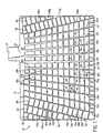
- FIG 1 shows a front view of a battery grid made in accordance with one version of the method of the present invention.
- the grid is a stamped grid made of a lead alloy grid material coated with a lead alloy, and functions in the same manner as other battery grids known in the art. It should be noted that an infinite number of grid designs may result from the present invention and therefore, it is not the intent of the following description to limit the invention to the grid design shown in Figure 1, which is presented for the purposes of illustration.
- the grid 10 comprises a frame that includes a top frame element 12, first and second side frame elements 14 and 16, and a bottom frame element 18.
- the grid 10 includes a series of grid wires that define open areas 20 that hold the electrochemical paste (not shown) that provides the current generation.
- a current collection lug 22 is integral with the top frame element 12 and is offset from the center of the top frame element 12.
- the top frame element 12 includes an enlarged conductive section 24 directly beneath the lug 22, and has the shape shown to optimize current conduction to the lug 22.
- a series of radially extending vertical grid wire elements 26a-26o form part of the grid 10.
- the vertical wire elements 26c-26n are connected to the top frame element 12 and the bottom frame element 18, the vertical wire elements 26a-26b are connected to the top frame element 12 in the first side frame element 14, and the vertical wire element 26o is connected to the top frame element 12 and the side frame element 16, as shown.
- the vertical wire element 26i is parallel to the side elements 14 and 16, and the remaining vertical wire elements 26a-26h and 26j-26o extend radially toward an imaginary intersecting point along a radius line running through the vertical element 26i.
- the vertical wire elements 26a-26o become closer together when moving from the bottom element 18 towards the top element 12 and get farther apart when moving towards the left element 14 or the right element 16 from the vertical element 26i.
- the grid 10 also includes a plurality of horizontal or cross wire elements.
- the cross wire elements include a set of parallel horizontal wire elements 30 positioned in a middle portion of the grid 10.
- the grid 10 includes a first set of cross wire elements 32 connected between the left frame element 14 and the vertical element 26a that are parallel to each other, a second set of cross wire elements 34 connected between the vertical elements 26a and 26b that are parallel to each other, and a third set of cross wire elements 36 connected between the vertical elements 26b and 26c that are parallel to each other at the left side of the grid 10.
- the grid 10 includes a fourth set of cross wire elements 38 connected between the vertical elements 26n and 26o that are parallel to each other and a fifth set of cross wire elements 40 connected between the vertical element 26o and the right frame element 16 that are parallel to each other at the right side of the grid, as shown.
- a series of short support wires 42 are connected to the bottom frame member 18 as shown.
- each grid wire section may have a different cross-sectional configuration, or each grid wire section may have the same cross-sectional configuration. However, it is preferred that each grid wire section have the same cross-sectional configuration. It is also important to note that although certain features of the invention have been illustrated in Figures 2-6A by way of cross-sectional views of vertical grid wires, the same .cross-sectional views could apply when taking a cross-section of horizontal grid wires. In other words, the similar deformation methods as illustrated in Figures 2 to 6A can also be applied to the horizontal wire elements. Depending on the needs, a grid can be deformed at the vertical wire elements only, or at both the vertical and horizontal wire elements, or not deformed at any of the wire elements,
- Figure 2 shows a cross-section of a section of vertical wire element 26h taken at a position between the opposed ends of the grid wire section. It can be seen that at the position between the opposed ends of this grid wire section, the cross-section of the grid wire includes a grid wire base 90a which is substantially an octagon, and an alloy coating 92a. Also shown in phantom at 93 is the interface between the grid wire base 90 and the alloy coating 92 below the opposed flat planar surfaces 33 of the grid. It can be appreciated by those in the art that a battery grid wire section or node will not have a perfect geometric configuration and that the rounding of edges and comers of a grid wire section, base, coating surface, or node is often the result of a manufacturing operation. For this reason, the description of cross-sectional shapes in the specification will be proceeded by the word "substantially" to indicate that the cross-sectional shape may vary somewhat from a perfect geometric shape.
- Figure 3 shows a cross-section of a section of vertical wire element 26i taken at a position between the opposed ends of the grid wire section. It can be seen that at the position between the opposed ends of this grid wire section, the cross-section of the grid wire includes a grid wire base 90b has been rotated 45 degrees in relation to the node and has a substantially rectangular cross-section. The cross-section of the grid wire also shows an alloy coating 92b. Also shown in phantom at 93 is the interface between the grid wire base 90b and the alloy coating 92b below the opposed flat planar surfaces 33 of the grid.
- Figure 4 shows a cross-section of a section of vertical wire element 26j taken at a position between the opposed ends of the grid wire section. It can be seen that at the position between the opposed ends of this grid wire section, the cross-section of the grid wire includes a grid wire base 90c which is substantially a hexagon and an alloy coating 92c.
- the grid wire base 90c has opposed surfaces which are coplanar with the surface of the adjacent nodes. Also shown in phantom at 93 is the interface between the grid wire base 90c and the alloy coating 92c below the opposed flat planar surfaces 33 of the grid.
- Figure 5 shows a cross-section of a section of vertical wire element 26k taken at a position between the opposed ends of the grid wire section. it can be seen that at the position between the opposed ends of this grid wire section, the cross-section of the grid wire includes a grid wire base 90d which is substantially a diamond and an alloy coating 92d. Also shown in phantom at 93 is the interface between the grid wire base 90d and the alloy coating 92d below the opposed flat planar surfaces 33 of the grid.
- Figure 6A shows a cross-section of a section of vertical wire element 26I taken at a position between the opposed ends of the grid wire section.
- This figure shows the configuration of a conventional stamped battery grid wherein the cross section of the node and the cross-section at all positions along the grid wire section are substantially rectangular and the surfaces of the node and grid wire section (which includes a grid wire base 90e) include an alloy coating 92e. Also shown in phantom at 93 is the interface between the grid wire base 90e and the alloy coating 92e below the opposed flat planar surfaces 33 of the grid.
- Figure 6B shows another version of the cross-section of a section of vertical wire element 261 taken at a position between the opposed ends of the grid wire section wherein the grid does not include an alloy coating. It can be seen that the cross-section of the node and the cross-section at all positions along the grid wire section are substantially rectangular and the cross-sectional area of each grid wire does not extend above or below opposed flat planar surfaces 33 of the grid.
- Figure 6C shows yet another version of the cross-section of a section of vertical wire element 261 taken at a position between the opposed ends of the grid wire section.
- a grid wire base 90g and an alloy coating 92g.
- the alloy coating 92g is disposed on the flat planar surfaces 33 of the grid; however, no alloy coating is present on surfaces 91g of the grid wire element that are transverse to the flat planar surfaces 33.
- the grid of Figure 6C may be produced by the method of U.S. Patent Nos. 4,906,540 and 4,761,356.
- Figure 6A shows the configuration of a conventional stamped battery grid that has been coating with an alloy coating 92e after stamping.
- the cross section of the node and the cross-section at all positions along the grid wire section comprising the grid wire base 90e are substantially rectangular.
- the surface of the alloy coating 92e is slightly rounded at the regions near the four comers of the grid wire base 90e.
- the slightly rounded grid wires allow the paste to flow around the wire.
- the rough surface of the wires provide a mechanical graft and interlock of paste particles. Therefore, the contact between the grid and the battery paste is good and the plate is strong.
- Figure 6B shows the configuration of a conventional stamped battery grid wherein the cross section of the node and the cross-section at all positions along the grid wire section 90f are substantially rectangular.
- the battery paste When the battery paste is cured and dried, it will shrink and generate tensile force at the paste / grid interface.
- the tensile force at the paste / grid wire interface is at a maximum when the wire surface is perpendicular to the grid surface and at a minimum when the wire surface is parallel to the grid surface. As a result, a gap is formed between the grid wire and the paste at the location where the tensile force is the maximum.
- This type of plate is weak and the paste will fall off easily. Because of a lack of contact between the paste and the grid, a battery made with this type of plate is much more difficult to form, performs poorly in certain reserve capacity tests, and does not exhibit satisfactory cycle life.
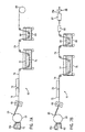
- FIG. 7A there is shown one apparatus, indicated generally at 50, for practicing the method of the present invention and for forming a battery grid in accordance with the invention.
- the apparatus 50 includes a heated lead pot 61a, which contains the molten lead alloy 62 that forms the base of the battery grids, and an internally cooled rotating casting drum 63.
- the molten lead alloy 62 contacts the cooled drum surface and freezes to form a solid lead alloy strip 65 of substantially constant width and thickness.
- a suitable lead alloy strip drum casting device that may be used in the apparatus 50 is shown and described in U.S. Patent No.
- the lead alloy strip 65 may optionally be rolled by rollers 64 to change the thickness and grain structure of the strip 65.
- the continuous strip 65 is then fed into a punching station 71 wherein a series of interconnected battery grids is formed by punching grid material out of the continuous strip 65.
- the strip 65 is maintained as a continuous strip and preferably the interconnected battery grid shapes and formed in a progressive punching operation, i.e., features are added to the battery grid through several punching operations.
- the punching station 71 may form a strip of interconnected battery grids, each of which has a configuration such as that shown in Figure 1.
- the battery grid wire sections of the strip may optionally be processed in a coining station 73.
- the coining station 73 is used to deform or coin the grid wires so that the grid wires have a cross-section similar to one of the grid wire cross-sections 90a, 90b, 90c or 90d shown in Figures 2-5.
- the coining station 73 may include a die or dies that deform the rectangular cross-section of the grid wires of the punched grid into an octagonal cross-section 90a as shown in Figure 2.
- the other exemplary wire cross-sections shown in Figures 3-5 may also be formed.
- the strip of punched (and optionally, coined) interconnected battery grids 74 exiting the punching station 71 (and optionally, the coining station 73) is fed through an alloy coating bath 76 that contains a molten lead alloy 77 to form, a strip of alloy coaled interconnected battery grids 79.
- the length of the alloy coating bath 76 may vary with the composition of the molten lead alloy 77, the thickness of the alloy coating to be deposited, and the rate at which the strip of punched interconnected battery grids 74 moves through the alloy coating bath 76.
- the strip of alloy coated interconnected battery grids 79 is then fed through a quench bath 83 containing quench fluid 84 (preferably water) and is coiled onto a take up reel 85.
- the quenching preserves the resolutionized grains of the strip of alloy coated interconnected battery grids 79 in a much more stable condition.
- the reel of alloy coated interconnected battery grids 79 may then be age hardened. While the reel of alloy coated interconnected battery grids 79 can be age hardened at room temperature (i.e., 25°C), it is preferred to age harden the reel of alloy coated interconnected battery grids 79 at an elevated temperature (i.e., above 25°C). Thereafter, the reel of alloy coated interconnected battery grids 79 may be uncoiled and fed to a paster (such as that shown and described in U.S. Patent No. 4,606,383) and parted into battery plates (as is known in the art) for assembly into a battery. Alternatively, the reel of alloy coated interconnected battery grids 79 may be uncoiled and divided into individual battery grids which are subsequently pasted to form battery plates.
- FIG. 7B there is shown another apparatus, indicated generally at 51, for practicing the method of the invention and for forming a battery grid in accordance with the invention.
- a strip of alloy coated interconnected battery grids 79 is produced using the casting drum 63, the punching station 71, the coining station 73 (if desired), the alloy coating bath 76 and the quench tank 83 as in the apparatus 50 of Figure 7A.
- the strip of alloy coated interconnected battery grids 79 enters an oven 86 after exiting the quench tank 83 in order to immediately age harden the strip of alloy coated interconnected battery grids 79 after quenching.
- the strip of alloy coated interconnected battery grids 79 is fed through a paster 87 where conventional battery paste is applied to the strip of alloy coated interconnected battery grids 79.
- a strip of pasted alloy coated interconnected battery grids 79a exits the paster 87 and is separated into individual battery plates in a parter 88 before assembly into a battery.
- FIG 7C there is shown another apparatus, indicated generally at 52, for practicing the method of the invention.
- a lead alloy strip 65 is formed using the casting drum 63 as in the apparatus 50 of Figure 7A.
- the lead alloy strip 65 is then expanded into a strip of interconnected battery grids 75 in an expander 72.
- a suitable apparatus for expanding the lead alloy strip 65 into the strip of interconnected battery grids 75 is shown and described in U.S. Patent No. 4,291,443 which is incorporated herein by reference.
- the battery grid wire sections of the strip may optionally be processed in a coining station 73 as described above with reference to the apparatus 50 of Figure 7A.
- the strip of interconnected battery grids 75 is then fed through the alloy coating bath 76 to form a strip of alloy coated interconnected battery grids 80 which is quenched in quench tank 83 and coiled onto take up reel 85.
- the reel of alloy coated interconnected battery grids 80 may then be heated to age harden the interconnected battery grids 80.
- the strip of interconnected battery grids 80 may be uncoiled and fed to a paster and parted into battery plates that are assembled into a battery.
- the reel of alloy coated interconnected battery grids 80 may be uncoiled and divided into individual battery grids which are subsequent pasted to form battery plates.
- FIG 7D there is shown another apparatus, indicated generally at 53, for practicing the method of the invention.
- a strip of alloy coated interconnected battery grids 80 is produced using the casting drum 63, the expander 72, the coining station 73, the alloy coating bath 76 and the quench tank 83 as in the apparatus 52 of Figure 7C.
- the strip of alloy coated interconnected battery grids 80 enters an oven 86 immediately after exiting the quench tank 83 in order to age harden the strip of alloy coated interconnected battery grids 80.
- the strip of alloy coated interconnected battery grids 80 is fed through a paster 87 where conventional battery paste is applied to the strip of alloy coated interconnected battery grids 80.
- a strip of pasted alloy coated interconnected battery grids 80a exits the paster 87 and is separated into individual battery plates in a parter 88 before assembly into a battery.
- the apparatus 50 of Figure 7A and the apparatus 51 of Figure 7B are particularly advantageous in that complex battery grid shapes (such as that shown in Figure 1) may be produced using the punching station 71 and optionally, the coining station 73.
- the expander 72 used in the apparatus 52 of Figure 7C and the apparatus 53 of Figure 7D produces a continuous length of expanded metal grids that are limited in wire pattern, wire shape, and lead distribution.
- the apparatus 50 of Figure 7A and the apparatus 51 of Figure 7B produce a continuous length of punched grids having optimized grid wire patterns.
- asymmetric and offset grid wire patterns improved grid wire thickness control (grid wire aspect ratios), improved grid wire shape control, improved lead distribution in the grid (percent lead distribution from the top to the bottom of the grid), and grain control.
- the corrosion performance is enhanced because of the relatively stress free grain structure and low porosity of the punched sheet.
- the punching process does not substantially deform the grain or add other stresses into the grid which might lead to corrosion initiation sites.
- the electrical performance is enhanced as a result of unique and optimized grid wire patterns, improved control of grid wire size and optimized lead distribution within the grid.
- the apparatus 50 of Figure 7A and the apparatus 51 of Figure 7B produce a battery grid that has the advantages of optimized grid wire patterns and the advantages of an alloy coating.
- FIG 8A there is shown another apparatus, indicated generally at 54, for practicing the method of the present invention and for forming a battery grid in accordance with the invention.
- the apparatus 54 includes a heated lead pot 61 b, which contains the molten lead alloy 62 that forms the base of the battery grids, and a pair of twin casting rollers 66. In operation, the molten lead alloy 62 contacts the roller surfaces and freezes to form a solid lead alloy strip 68 of substantially constant width and thickness.
- a suitable lead alloy strip roll casting device that may be used in the apparatus 54 is shown and described in U.S. Patent No. 4,498,519, which is incorporated herein by reference.
- the lead alloy strip 68 may optionally be further rolled by rollers 67 to change the thickness and grain structure of the strip 68.
- the continuous strip 68 is then fed into a punching station 71 wherein a series of interconnected battery grids is formed by punching grid material out of the continuous strip 68.
- the strip 68 is maintained as a continuous strip and preferably the interconnected battery grid shapes and formed in a progressive punching operation, i.e., features are added to the battery grid through several punching operations.
- the punching station 71 may form a strip of interconnected battery grids, each of which has a configuration such as that shown in Figure 1.
- the battery grid wire sections of the strip may optionally be processed in a coining station 73.
- the coining station 73 is used to deform or coin the grid wires so that the grid wires have a cross-section similar to one of the grid wire cross-sections 90a, 90b, 90c or 90d shown in Figures 2-5.
- the coining station 73 may include a die or dies that deform the rectangular cross-section fo the grid wires of the punched grid into an octagonal cross-section 90a as shown in Figure 2.
- the other exemplary wire cross-sections shown in Figures 3-5 may also be formed.
- the strip of punched (and optionally, coined) interconnected battery grids 74 exiting the punching station 71 (and optionally, the coining station 73) is then fed through an alloy coating bath 76 that contains a molten lead alloy 77 to form a strip of alloy coated interconnected battery grids 79, as described with reference to Figure 7A.
- the strip of alloy coated interconnected battery grids 79 is then fed through a quench fluid 84 and is coiled onto a take up reel 85.
- the reel of alloy coated interconnected battery grids 79 may then be heated to age harden the interconnected battery grids 79.
- the reel of alloy coated interconnected battery grids 79 may be uncoiled and fed to a paster and parted into battery plates that are assembled into a battery. Alternatively, the reel of alloy coated interconnected battery grids 79 may be uncoiled and divided into individual battery grids which are subsequently pasted to form battery plates.
- FIG 8B there is shown another apparatus, indicated generally at 55, for practicing the method of the invention and for forming a battery grid in accordance with the invention.
- a strip of alloy coated interconnected battery grids 79 is produced using the twin roll caster 66, the punching station 71, the coining station 73 (if desired), the alloy coating bath 76 and the quench tank 83 as in the apparatus 54 of Figure 8A.
- the strip of alloy coated interconnected battery grids 79 enters an oven 86 after exiting the quench tank 83 in order to age harden the strip of alloy coated interconnected battery grids 79.
- the strip of alloy coated interconnected battery grids 79 is fed through a paster 87 where conventional battery paste is applied to the strip of alloy coated interconnected battery grids 79.
- a strip of pasted alloy coated interconnected . battery grids 79a exits the paster 87 and is separated into individual battery plates in a parter 88.
- FIG 8C there is shown another apparatus, indicated generally at 56, for practicing the method of the invention.
- a lead alloy strip 68 is formed using the twin roll caster 66 as in the apparatus 54 of Figure 8A.
- the lead alloy strip 68 is then expanded into a strip of interconnected battery grids 75 in an expander 72.
- a suitable apparatus for expanding the lead alloy strip 68 into the strip of interconnected battery grids 75 is shown and described in U.S. Patent No. 4,291,443.
- the battery grid wire sections of the strip may optionally be processed in a coining station 73 as described above with reference to the apparatus 50 of Figure 7A.
- the strip of interconnected battery grids 75 is then fed through the alloy coating bath 76 to form a strip of alloy coated interconnected battery grids 80 which is quenched in quench tank 83 and coiled onto take up reel 85.
- the reel of alloy coated interconnected battery grids 80 may then be heated to age harden the interconnected battery grids 80.
- the strip of interconnected battery grids 80 may be uncoiled and fed to a paster and parted into battery plates that are assembled into a battery.
- the reel of alloy coated interconnected battery grids 80 may be uncoiled and divided into individual battery grids which are subsequently pasted to form battery plates.
- FIG 8D there is shown another apparatus, indicated generally at 57, for practicing the method of the invention.
- a strip of alloy coated interconnected battery grids 80 is produced using the twin roll caster 66, the expander 72, the coining station 73 (if desired), the alloy coating bath 76 and the quench tank 83 as in the apparatus 56 of Figure 8C.
- the strip of alloy coated interconnected battery grids 80 enters an oven 80 after exiting the quench tank 83 in order to age harden the strip of alloy coated interconnected battery grids 80.
- the strip of alloy coated interconnected battery grids 80 is fed through a paster 87 where conventional battery paste is applied to the strip of alloy coated interconnected battery grids 80.
- a strip of pasted alloy coated interconnected battery grids 80a exits the paster 87 and is separated into individual battery plates in a parter 88.
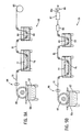
- FIG 9A there is shown another apparatus, indicated generally at 58, for practicing the method of the present invention and for forming a battery grid in accordance with the invention.
- the apparatus 58 includes a heated lead pot 61c. which contains the molten lead alloy 62 that forms the base of the battery grids, and a casting drum 69. In operation, the molten lead alloy 62 contacts the casting drum surfaces and freezes to form a strip of interconnected battery grids 70.
- a suitable casting device that may be used in the apparatus 58 to form the strip of interconnected battery grids 70 is shown and described in U.S. Patent No. 4,349,067, which is incorporated herein by reference.
- the strip of interconnected battery grids 70 removed from the surface of the casting drum 69 may be fed through one or more sets of rollers 98 in order to reduce the thickness of the strip of interconnected battery grids 70 as is shown and described in U.S. Patent No. 5,611,128, which is incorporated herein by reference.
- the strip of interconnected battery grids 70 is then fed through an alloy coating bath 76 that contains a molten lead alloy 77 to form a strip of alloy coated interconnected battery grids 81, as described with reference to Figure 7A.
- the strip of alloy coated interconnected battery grids 81 is then fed through a quench fluid 84 and is coiled onto a take up reel 85.
- the reel of alloy coated interconnected battery grids 81 may then be heated to age harden the interconnected battery grids 81.
- the reel of alloy coated interconnected battery grids 81 may be uncoiled and fed to a paster and parted into battery plates that are assembled into a battery.
- the reel of alloy coated interconnected battery grids 81 may be uncoiled and divided into individual battery grids which are subsequently pasted to form battery plates.
- FIG. 9B there is shown another apparatus, indicated generally at 59, for practicing the method of the present invention and for forming a battery grid in accordance with the invention.
- a strip of alloy coated interconnected battery grids 81 is produced using the casting drum 69, optionally the rollers 98, the alloy coating bath 76 and the quench tank 83 as in the apparatus 58 of Figure 9A.
- the strip of alloy coated interconnected battery grids 81 enters an oven 86 after exiting the quench tank 83 in order to age harden the strip of alloy coated interconnected battery grids 81.
- the strip of alloy coated interconnected battery grids 81 is fed through a paster 87 where conventional battery paste is applied to the strip of alloy coated interconnected battery grids 81.
- a strip of pasted alloy coated interconnected battery grids 81 a exits the paster 87 and is separated into individual battery plates in a parter 88:
- the strip of interconnected battery grids 74 may optionally be fed through a fluxing station (not shown) before entering the alloy coating bath 76 in order to remove oxides from the surface of the strip of interconnected battery grids 74.
- a fluxing station may include a pool of flux in a tray underlying the advancing strip of interconnected battery grids 74, a rotating roller that absorbs and picks up flux from the pool and applies it to the underside of the strip of interconnected battery grids 74, and a nozzle overlying the strip of interconnected battery grids 74 for spraying flux onto the topside of the strip of interconnected battery grids 74.
- Other techniques e.g.
- wetted sponges/applicators for applying the flux to the strip of interconnected battery grids 74 may also be used.
- the alloy coating may be applied to the strip of interconnected battery grids 74 by spraying the alloy onto the strip of interconnected battery grids 74.
- the alloy coating bath 76 is modified such that a stream of inert gas (e.g., nitrogen or argon) may be purged or blown into the molten lead alloy 77 in the alloy coating bath 76.
- a stream of inert gas e.g., nitrogen or argon
- the inert gas e.g., nitrogen or argon
- the inert gas is blown into the molten lead alloy 77 such that bubbles form in the molten lead alloy 77.
- the alloy coating that forms on the strip of interconnected battery grids 74 is porous and therefore, has a much higher surface area, which further enhances the grid/active material adhesion; (2) the alloy coating that forms on the strip of interconnected battery grids 74 has a lower mass and lower cost as compared to an alloy coating that forms on the strip of interconnected battery grids 74 without the introduction of inert gas into the molten lead alloy 77; (3) the inert gas acts as a shielding film as it is leaving the alloy coating bath 76 which prevents the top of the molten alloy bath from oxidizing thereby reducing dross and contamination of the alloy coating bath 76.
- example grid materials and example coating materials that may be used to form a battery grid in accordance with the invention may be described.
- the lead alloy used to produce the solid lead alloy strip 65 in the casting drum 63 of the apparatus of any of Figures 7A-7D is selected in order to provide a cast alloy strip that may be punched or expanded into a strip of interconnected battery grids having an alloy composition suitable for the intended application of the lead-acid battery. For example, if a lead-acid battery is to be sold as a "maintenance-free" battery, a lead-calcium alloy will be selected for use as the lead alloy applied to the casting drum 63.
- an alloy having lead and calcium may also contain other alloyants such as tin, aluminum and silver.
- the term "lead-calcium alloy” is not intended to be limited strictly to binary lead-calcium alloys, but shall also include alloys having lead and calcium as well as other alloying elements which are not deleterious to the battery or the maintenance-free character thereof.
- the alloying elements in the lead alloy can be varied to provide optimum performance of the casting drum 63 of the apparatus of any of Figures 7A-7D.
- the lead alloy used to produce the solid lead alloy strip 68 in the twin roll casting rollers 66 of the apparatus of any of Figures 8A-8D may be selected in order to provide a cast alloy strip that may be punched or expanded into a strip of interconnected battery grids having an alloy composition suitable for the intended application of the lead-acid battery. If a lead-acid battery is to be sold as a "maintenance-free" battery, a lead-calcium alloy as defined herein will be selected for use as the lead alloy applied to the twin roll casting rollers 66. The alloying elements in the lead alloy can be varied to provide optimum performance of the casting drum 66.
- the lead alloy used to produce the strip of interconnected battery grids 81 using the casting drum 69 of the apparatus of any of Figures 9A-9B may be selected in order to provide a strip of interconnected battery grids 81 having an alloy composition suitable for the intended application of the lead-acid battery. If a lead-acid battery is to be sold as a "maintenance-free" battery, a lead-calcium alloy as defined herein will be selected for use as the lead alloy applied to the casting drum 69. The alloying elements in the lead alloy can be varied to provide optimum performance of the casting drum 69.
- One example lead-calcium alloy that is useful in the present invention includes lead, from about 0.060 wt.% to about 0.070 wt.% calcium, and from about 1.20 wt.% to about 1.50 wt.% tin.
- Another example lead-calcium alloy that is useful in the present invention includes lead, no less than about 0.8% tin, tin in a ratio to calcium of greater than about 12:1, and silver in the range of about 0 to about 0.02%, the percentages being based upon the total weight of the lead-based alloy.
- This example lead-calcium alloy is fully described in U.S. Patent No. 6,117,594.
- each of the apparatus shown in Figures 7A-9B produces a strip of interconnected battery grids that is subsequently coated with a lead alloy in the alloy coating bath 76.
- the lead alloy selected for the coating varies depending on the alloy used to produce the strip of interconnected battery grids.
- suitable lead alloys for the coating include lead-tin and lead-antimony alloys.
- the precise composition of the coating is not particularly critical in terms of extending the lives of batteries. On the other hand, there are two general rules applicable to the selection of the lead alloy coating composition.
- the composition of the coating should be selected so as to provide a melt having a melting point which is sufficiently less than the melting point of the lead-calcium alloy strip of interconnected battery grids (e.g., about 620°F for a typical Pb - 0.07 wt.% Ca - 1 to 1.5 wt.% tin alloy) so as to preclude complete melting of the strip of interconnected battery grids while it is immersed in the melt. Melting of the surface of the lead-calcium alloy strip of interconnected battery grids is acceptable and, in fact, may be desirable to promote metallurgical bonding of the alloy coating to the strip of interconnected battery grids.
- the composition of the coating should be such that there is sufficient tin, antimony or other alloying elements present to dope the corrosion layer on the surface of the strip of interconnected battery grids (i.e., at the grid-active material interface) with oxides of the tin, antimony or other alloying elements, and thereby improve the conductivity of the corrosion layer and promote better adhesion of the leady active material to the grid.
- Suitable lead-antimony alloys for coating the strip of interconnected battery grids include lead alloys having an antimony content varying from about 1% by weight to about 10% by weight. Other additives such as tin from about 1 wt.% to about 10 wt.% may also be used with the antimonial lead.
- lead-antimony alloy is not intended to be limited to alloys containing just lead and antimony, but rather is intended to include other low melting alloys thereof which do not negate the intended effects of the antimony or are otherwise deleterious to a battery.
- the antimony content in the lead alloy coating will preferably be between about 0.5 wt.% and about 3 wt.%, and preferably the tin content in the lead alloy will be between about 2 wt.% and about 5 wt.% so as to have a melting point of about 590°F.
- suitable lead-tin alloys may be used as all melt at lower temperatures than the typical lead-calcium alloy strip of interconnected battery grids.
- Lead-tin alloys will preferably comprise about 1 wt.% to about 10 wt.% tin, but otherwise will be determined primarily on the basis of cost owing to the high cost of tin.
- One example alloy includes lead and about 4 wt.% to about 6 wt.% tin.
- Other alloyants could be added and therefore, the term lead-tin alloy is not intended to be limited to alloys containing just lead and tin, but rather intended to include other low melting alloys thereof which do not negate the intended effects of the tin or are otherwise deleterious to a battery or the maintenance-free character thereof.
- the precise temperature of the melt is not particularly critical so long as it is not so hot as to completely melt the strip of interconnected battery grids in the brief time that the strip of interconnected battery grids are immersed in the melt.
- the melt temperature will, in many respects, be determined by the composition (and hence melting point) of the strip of interconnected battery grids being coated.
- the temperature of the melt be maintained at a temperature that is at least about 20°F below the melting point of the strip of interconnected battery grids.
- it is desirable that the temperature be sufficiently high as to melt some low melting phases on the surface of the strip of interconnected battery grids to promote better bonding of the coating to the strip of interconnected battery grids.
- a continuous strip was prepared from a lead-alloy having the following composition: 0.0425 wt.% calcium. 0.925 wt.% tin, 0.013 wt.% aluminum, 0.0125 wt.% silver and balance lead.
- a series of interconnected battery grid shapes were then formed in the strip in a progressive punching operation, i.e., features were added to the battery grid through several punching operations.
- the battery grid wire sections of the strip were then processed in a coining station to coin the grid wires so that the grid wires had a cross-section similar to the grid wire cross-sections 90c in Figure 4.
- the interconnected battery grids were then divided into individual grids.
- the grids were then pasted with a conventional battery paste and formed into battery cells.
- the battery cells were then cycled in accordance with the SAE J240 life test procedure at a temperature of 75"C (167°F) to measure the service life.
- a continuous strip was prepared from a lead-alloy having the following composition: 0.0425 wt.% calcium, 0.925 wt.% tin, 0.013 wt.% aluminum, 0.0125 wt.% silver and balance lead.
- a series of interconnected battery grid shapes were then formed in the strip in a progressive punching operation, i.e., features were added to the battery grid through several punching operations.
- the battery grid wire sections of the strip were then processed in a coining station to coin the grid wires so that the grid wires had a cross-section similar to the grid wire cross-sections 90c in Figure 4.
- the interconnected battery grids were then divided into individual grids.
- the grids were then hand dipped into a pot of molten 94 wt.% lead - 6 wt.% tin coating alloy. The grids were dipped slowly into the melt until they bottomed out in the pot and then slowly withdrawn at the same rate for a total immersion time of about 2 seconds. The coating was uniform with no excess buildup on the grid wires or the edges of the grids.
- the grids were then pasted with a conventional battery paste and formed into battery cells. The battery cells were then cycled in accordance with the SAE J240 life test procedure at a temperature of 75°C (167°F) to measure the service life.
- the number of cycles for battery cells having lead -tin alloy coated grids prepared in accordance with Example 2 was 20% higher than the number of cycles for the control battery cells having uncoated grids prepared in accordance with Example 1. This demonstrates that batteries including grids made in accordance with the present invention will have better cycle life performance than batteries including conventional grids.
- a continuous strip was prepared from a lead-alloy having the following composition: 0.0425 wt.% calcium, 0.925 wt.% tin, 0.013 wt.% aluminum, 0.0125 wt.% silver and balance lead.
- a series of interconnected battery grid shapes were then formed in the strip in a progressive punching operation, i.e., features were added to the battery grid through several punching operations.
- the battery grid wire sections of the strip were then processed in a coining station to coin the grid wires so that the grid wires had a cross-section similar to the grid wire cross-sections 90c in Figure 4.
- the interconnected battery grids were then divided into individual grids.
- the grids were then hand dipped into a pot of molten 94 wt.% lead - 3 wt.% tin - 3 wt.% antimony coating alloy.
- the grids were dipped slowly into the melt until they bottomed out in the pot and then slowly withdrawn at the same rate for a total immersion time of about 2 seconds.
- the coating was uniform with no excess buildup on the grid wires or the edges of the grids.
- the grids were then pasted with a conventional battery paste and formed into battery cells.
- the battery cells were then cycled in accordance with the SAE J240 life test procedure at a temperature of 75°C (167°F)to measure the service life.
- the number of cycles for battery cells having lead - tin - antimony alloy coated grids prepared in accordance with Example 3 was 47% higher at the last reading than the number of cycles for the control battery cells having uncoated grids prepared in accordance with Example 1.
- the battery cells of Example 3 continue on test as the lower voltage cutoff for the SAE J240 has not been reached. This demonstrates that batteries including grids made in accordance with the present invention will have better cycle life performance than batteries including conventional grids.
- the present invention provides a method that can increase the adherence of battery active material to a battery grid produced by a continuous process, such as strip expansion, strip punching, or continuous casting.
- the method of the present invention increases the cycle life of a battery by enhancing the adhesion between the battery paste material and the battery grid.
- a battery manufacturer can take advantage of a low cost continuous grid making process without the drawbacks associated with inadequate paste adhesion.
Landscapes
- Chemical & Material Sciences (AREA)
- Chemical Kinetics & Catalysis (AREA)
- Electrochemistry (AREA)
- General Chemical & Material Sciences (AREA)
- Engineering & Computer Science (AREA)
- Materials Engineering (AREA)
- Manufacturing & Machinery (AREA)
- Composite Materials (AREA)
- Cell Electrode Carriers And Collectors (AREA)
- Battery Electrode And Active Subsutance (AREA)
Abstract
Description
- The present invention retates to the modification of battery grids of the type used in lead-acid storage batteries, and more particularly, it relates to a modification af the surface finish of the battery grids of a lead-acid storage battery to improve paste adhesion and the service life of the battery.
- Lead-acid storage batteries typically comprise several celt elements which are encased in separate compartments of a container containing sulfuric acid electrolyte. Each cell element includes at least one positive plate, at least one negative plate, and a porous separator positioned between each positive and negative plate. The positive and negative plates each comprise a lead or lead alloy grid that supports an electrochemically active material. The active material is a lead based material (i.e., PbO, PbO2, Pb or PbSO4 at different charge/discharge stages of the battery) that is pasted onto the grid. The grids provide an electrical contact between the positive and negative active materials which serves to conduct current.
- Lead-acid battery manufacturing technologies and materials have improved dramatically in the last few decades. One early revolution was the use of battery grid materials that produce a "maintenance-free" battery. Because pure lead is too soft for the manufacturing processes used to form battery grids, various alloying elements have been added to lead over the years to produce battery grids of sufficient strength to withstand battery manufacturing processes. For example, antimony was added to lead as lead-antimony alloys were found to be capable of being formed into battery grids at acceptable commercial rates by way of gravity casting techniques. However, it was discovered that when a lead-antimony alloy is used in battery grids, water loss occurs because of gassing. Therefore, batteries having lead-antimony grids required periodic maintenance. i.e., the addition of water to the battery. In order to lower the gassing rate of batteries, lead-calcium battery grids were developed. Batteries using lead-calcium alloy grids have low-gassing rates, and therefore, do not require the addition of water. As a result, the use of lead-calcium alloy battery grids has led to the introduction of "maintenance-free" batteries.
- Another significant revolution in lead-acid battery manufacturing has been the manufacturing of battery plates in a continuous process. instead of the traditional methods in which battery grids are made using a conventional gravity cast book mold operation and the cast grids are later pasted in a separate step. In a typical continuous battery plate making method, a lead alloy strip is manufactured, either by casting (namely, cast strip) or by casting and rolling (namely, wrought strip), and the strip is subsequently expanded or punched to generate the desired grid pattern in a strip of interconnected battery grids. Typically, lead alloys having a relatively high level of calcium are used in continuous grid making processes as higher calcium levels tend to increase the hardness of the battery grids which is beneficial in punching and expansion processes. Previously prepared active material battery paste (which may be prepared by mixing lead oxide, sulfuric acid, water, and optionally dry additives, such as fiber and expander) is then applied to the strip of interconnected battery grids and the strip is parted into single battery plates. The main advantages of continuous battery plate making are production rate, dimensional control, thinner plates, lower strap rate and lower manufacturing costs. The pasted plates are next typically cured for many hours under elevated temperature and humidity to oxidize free lead (if any) and adjust the crystal structure of the plate. After curing, the plates are assembled into batteries and electrochemically formed by passage of current to convert the lead sulfate or basic lead sulfate(s) to lead dioxide (positive plates) or lead (negative plates). This is referred to as the "formation" process.
- It is well known that lead-acid batteries will eventually fall in service through one or more of several failure modes. Among these failure modes is failure due to corrosion of the grid surface. Electrochemical action corrodes the grid surface and reduces the adhesion between the active material and the grid. In most instances, failure of the battery occurs when the grids are no longer able to provide adequate structural support or current flow due to the separation of the active material from the grid. It has been determined that negative lead-acid battery plates made by a continuous plate making method as described above have performed at least as well in service (cycle) life as negative plates made from conventional gravity cast book mold grids. However, positive lead-acid battery plates made by a continuous plate making method underperform in service (cycle) life as compared to gravity cast book mold grids, especially in the high temperature environment under the hood of today's more compact cars. In particular, lead-acid batteries having positive plates made by a continuous plate making method from lead-calcium alloys have proven to be relatively short-lived as determined by the SAE J240B Life Cycle Test (at 40°C and particularly at 75°C) owing to corrosion of the grid surface which forms an electrically resistive layer between the active material and the grid and seemingly reduces the adhesion between the active material and the grid over the course of the test. Lead-calcium grid batteries are particularly susceptible to early failure for the high temperature (75°C) J240 test, and are short-lived compared to similar batteries made with lead-antimony grids.
- Therefore, there have been efforts to improve the service life of a lead-acid battery having continuously manufactured plates, particularly by increasing the adhesion of positive grids to the active paste material. For example, a method for extending the cycle life of a lead-acid storage battery is disclosed in U.S. Patent No. 5,858,575. In this method, a continuous length of unexpanded strip or a continuous length of preexpanded grid strip, each of which is formed from a lead-calcium alloy, is coated with a layer of a tin, lead-antimony, lead-silver or lead-tin alloy by hot dipping in a melt of the alloy. The layer of metal on the surface of the grid promotes better adhesion of the active material paste to the grid.
- Another similar method is described in U.S. Patent No. 4,906,540 which discloses a method wherein a layer of a lead-tin-antimony alloy is roll-bonded to a strip formed of a lead-calcium alloy. The strip is then expanded into a continuous length of grids. It is stated that the surface layer of the lead-tin-antimony alloy enables the battery active material to be retained for a long period of time. The increased adhesion of the paste to the grid serves to improve the cycle life of the battery.
- Yet another similar method is described in Japanese Patent Publication No. 10-284085 which discloses a method wherein a coating of a lead-antimony-selenium alloy is fused to a lead-calcium-tin alloy strip and the strip is thereafter punched and/or expanded to form battery grids. The grids formed by this process are believed to increase battery life.
- Still another similar method is described in U.S. Patent No. 4,761,356 which discloses a method wherein a lead-calcium alloy strip is coated with a lead-tin alloy by dipping, spray coating or plating, and the coated alloy strip is thereafter punched or expanded to form a continuous strip of battery grids. The use of a process wherein the lead-calcium strip is punched or expanded after coating with a lead-tin alloy produces a grid with the lead-calcium alloy exposed at areas where grid material is punched out of the strip. The alloy coating is reported to improve recovery after overdischarge.
- The formation efficiency of lead-acid batteries also depends to a great extent on the positive plate, in particular, to the extent of conversion of lead monoxide (PbO) to lead dioxide (PbO2) in the active positive material. The high electrical potential required for formation appears to be related to the transformation of non-conductive paste materials to PbO2. A low formation efficiency of positive plates requires a high formation charge. Inefficient charging also leads to deficiencies in the resulting batteries assembled with such plates. Typically, the initial capacity (performance) of the battery is low if the battery is not completely formed, requiring additional cycling to reach specific performance values. It is well known that by increasing the adhesion between the paste mixture and the grid, formation efficiency can be improved. Among other things, the increased adhesion between the grid and the paste provides for improved interfacial contact between the grid and paste thereby improving current flow between the grid and paste.
- Thus, it can be seen that the adhesion between a battery grid and battery active material may affect, among other things, battery formation processes and battery service life. Accordingly, various methods, such as those mentioned above, have been proposed to Improve the adhesion between a battery grid and battery active material, and thereby improve battery service life.
- EP-A-0 795 917 discloses a method of mechanically coating lead alloys on expanded grids of a lead-acid battery.
- JP(A) 58075772 dicloses a method of electrolytically depositing lead on the surface of a strip of expanded grids for a lead-acid battery.
- US-A-5,989,749 discloses a stamped battery grid for a lead-acid battery with the grid wires having different cross-sections over their length.
- US-A-5,858,575 discloses hot dipped Pb-Ca grids for lead-acid batteries wherein the grid is coated after expansion and the coating covers all exposed surfaces of the grid.
- EP-A-0 348 702 discloses a method of coating electrode grids for a battery. The grids are dipped into a molten coating material with ultrasonic energy being applied to the melt.
- However, all of the aforementioned methods have certain disadvantages that limit the ability of these methods to attain maximum effectiveness in improving battery service life. For instance, the methods disclosed in U.S. Patent Nos. 4,906,540 and 4,761,356 and Japanese Patent Publication No. 10-284085 all form a battery grid by applying an alloy coating to a Strip and thereafter punching or expanding the strip to form battery grids. As a result the alloy coating will not be present on the grid wire surfaces that face the openings that are formed in the strip when the strip is punched or slit and expanded. Therefore. the beneficial effects of the alloy coating on paste adhesion and service life will be necessarily limited as the entire surface of the grid wires will not be coated. in addition, the coating methods disclosed in U.S. Patent No. 5,858,575 are used with expanded metal grids (as shown in Figure 1 of U.S. Patent No. 5,858,575) which are known to have inferior charge/discharge efficiency as compared to stamped grids, such as that shown in U.S. Patent No. 5,989,749. The decreased charge/discharge efficiency of the expanded grids also limits the service (cycle) life of a battery.
- Therefore, there continues to be a need in the battery manufacturing field for even more effective methods for improving the service life of a battery. More particularly, there is a need for a method that can more greatly increase the adherence of active material to a battery grid produced by a continuous process.
- This invention relates to a method as claimed in
Claim - The foregoing needs in the art are achieved by a method of forming battery grids or battery plates that includes the step of applying a lead alloy coating to a continuous strip of interconnected battery grids formed from a lead alloy grid material. Each of the interconnected battery grids, includes a grid network bordered by at least one frame element. The grid network comprises a plurality of spaced apart grid wire elements, each of which has opposed ends joined to one of a plurality of nodes thereby defining a plurality of open spaces in the grid network. In one version of the invention, the strip of interconnected battery grids is immersed in a melt of the lead alloy coating to apply the lead alloy coating to the strip of interconnected battery grids. The alloy coated strip of interconnected battery grids is subsequently pasted and cut into individual battery plates, or cut into individual battery grids for later pasting.
- Optionally, at least a portion of the grid wire elements are deformed (such as by coining) at a position intermediate the opposed ends of the grid wire element before the lead alloy coating is applied to the strip of interconnected battery grids. This produces grid wire elements wherein a first transverse cross-section taken at the position intermediate the opposed ends of the grid wire element differs from a second transverse cross-section taken at one of the opposed ends of the grid wire element. The strip of coated interconnected grids may also be quenched and thereafter age hardened.
- Various methods may be used to form the strip of interconnected battery grids. For example, grid material may be punched out of a continuous strip of grid material to form the strip of interconnected battery grids. Alternatively, the strip of interconnected battery grids may be formed by slitting and expanding a continuous strip of grid material. Also, the strip of interconnected battery grids may be formed by continuously casting a melt of the grid material (e.g., on a rotating drum).
- There are several advantages to coating the strip of interconnected battery grids after the grid network has been formed. First, the molten lead alloy coating transfers heat to the surface of the strip of interconnected battery grids thereby resotutionizing the surface of the strip of interconnected battery grids. The grains at the surface of the strip of interconnected battery grids recrystallize into larger grains which have an increased resistance to creep. Second, the alloy coating is applied to all surfaces of the grid network thereby improving paste adhesion on all grid wire surfaces, not just the grid wire surfaces parallel to the longitudinal plane of the strip of interconnected grids. Third, the alloy coating provides a cast-like surface structure with increased surface area on all surfaces of the grid network thereby improving adhesion on all grid wire surfaces, not just the grid wire surfaces parallel to the longitudinal plane of the strip of interconnected grids. In addition, increased surface area reduces current density, corrosion rate and increases charging ability.
- It is therefore an advantage of the present invention to provide a method that increases the cycle life of a battery by enhancing the adhesion between the battery active material and the battery grid.
- It is a further advantage to provide a method that increases the formation efficiency of a battery by enhancing the adhesion between the battery paste material and the battery grid.
- It is yet another advantage to provide a method that can modify the shape of wires of a battery grid made from a continuous process so that the paste can flow around the grid wires to improve the plate strength.
- It is still another advantage of the present invention to provide a method of making battery grids that allows a battery manufacturer to take advantage of a low cost continuous grid making process without the drawbacks associated with inadequate paste adhesion such as reduced formation efficiency and reduced cycle life.
- It is yet another advantage of the present invention to provide a method of making battery plates or battery grids that produces a battery grid having increased grain size near the surface of the battery grid.
- It is still another advantage of the present invention to provide a method of making battery plates or battery grids that produces a battery grid with increased surface area thereby increasing interfacial contact and mechanical bonding between the grid and battery paste.
- These and other features, aspects, and advantages of the present invention will become better understood upon consideration of the following detailed description, appended claims and accompanying drawings where:
- Figure 1 shows a front view of a battery grid made in accordance with one version of the method of the present invention:
- Figure 2 shows a cross-section of a vertical grid wire section taken along line 2-2 of Figure 1;
- Figure 3 shows a cross-section of a vertical grid wire section taken along line 3-3 of Figure 1;
- Figure 4 shows a cross-section of a vertical grid wire section taken along line 4-4 of Figure 1;
- Figure 5 shows a cross-section of a vertical grid wire section taken along line 5-5 of Figure 1;
- Figure 6A shows a cross-section of a vertical grid wire section taken along line 6-6 of Figure 1;
- Figure 6B shows a cross-section of a vertical grid wire section without an alloy coating taken along line 6-6 on Figure 1;
- Figure 6C shows a cross-section of a vertical grid wire section having a partial alloy coating taken along the line 6-6 of Figure 1;
- Figure 7A is a schematic illustration of one apparatus that may be used to practice the method of the present invention and produce a battery grid according to the invention.
- Figure 7B is a schematic illustration of another apparatus that may be used to practice the method of the present invention and produce a battery grid according to the invention;
- Figure 7C is a schematic illustration of yet another apparatus that may be used to practice the method of the present invention and produce a battery grid according to the invention;
- Figure 7D is a schematic illustration of still another apparatus that may be used to practice the method of the present invention and produce a battery grid according to the invention;
- Figure 8A is a schematic illustration of another apparatus that may be used to practice the method of the present invention and produce a battery grid according to the invention;
- Figure 8B is a schematic illustration of yet another apparatus that may be used to practice the method of the present invention and produce a battery grid according to the invention;
- Figure 8C is a schematic illustration of still another apparatus that may be used to practice the method of the present invention and produce a battery grid according to the invention;
- Figure 8D is a schematic illustration of another apparatus that may be used to practice the method of the present invention and produce a battery grid according to the invention;
- Figure 9A is a schematic illustration of yet another apparatus that may be used to practice the method of the present invention and produce a battery grid according to the invention;
- Figure 9B is a schematic illustration of still another apparatus that may be used to practice the method of the present invention and produce a battery grid according to the invention;
-
- It should be understood that the drawings are not necessarily to scale and that the embodiments are sometimes illustrated by graphic symbols, phantom fines, diagrammatic representations and fragmentary views. In certain instances, details which are not necessary for an understanding of the present invention or which render other details difficult to perceive may have been omitted. It should be understood, of course, that the invention is not necessarily limited to the particular embodiments illustrated herein.
- Like reference numerals will be used to refer to like or similar parts from Figure to Figure in the following description of the drawings.
- Figure 1 shows a front view of a battery grid made in accordance with one version of the method of the present invention. The grid is a stamped grid made of a lead alloy grid material coated with a lead alloy, and functions in the same manner as other battery grids known in the art. It should be noted that an infinite number of grid designs may result from the present invention and therefore, it is not the intent of the following description to limit the invention to the grid design shown in Figure 1, which is presented for the purposes of illustration.
- Referring now to Figure 1, the
grid 10 comprises a frame that includes atop frame element 12, first and secondside frame elements bottom frame element 18. Thegrid 10 includes a series of grid wires that defineopen areas 20 that hold the electrochemical paste (not shown) that provides the current generation. Acurrent collection lug 22 is integral with thetop frame element 12 and is offset from the center of thetop frame element 12. Thetop frame element 12 includes an enlargedconductive section 24 directly beneath thelug 22, and has the shape shown to optimize current conduction to thelug 22. - A series of radially extending vertical
grid wire elements 26a-26o form part of thegrid 10. Thevertical wire elements 26c-26n are connected to thetop frame element 12 and thebottom frame element 18, thevertical wire elements 26a-26b are connected to thetop frame element 12 in the firstside frame element 14, and the vertical wire element 26o is connected to thetop frame element 12 and theside frame element 16, as shown. Thevertical wire element 26i is parallel to theside elements vertical wire elements 26a-26h and 26j-26o extend radially toward an imaginary intersecting point along a radius line running through thevertical element 26i. Thevertical wire elements 26a-26o become closer together when moving from thebottom element 18 towards thetop element 12 and get farther apart when moving towards theleft element 14 or theright element 16 from thevertical element 26i. - The
grid 10 also includes a plurality of horizontal or cross wire elements. The cross wire elements include a set of parallelhorizontal wire elements 30 positioned in a middle portion of thegrid 10. Additionally, thegrid 10 includes a first set ofcross wire elements 32 connected between theleft frame element 14 and thevertical element 26a that are parallel to each other, a second set ofcross wire elements 34 connected between thevertical elements cross wire elements 36 connected between thevertical elements grid 10. Also, thegrid 10 includes a fourth set ofcross wire elements 38 connected between thevertical elements 26n and 26o that are parallel to each other and a fifth set ofcross wire elements 40 connected between the vertical element 26o and theright frame element 16 that are parallel to each other at the right side of the grid, as shown. A series ofshort support wires 42 are connected to thebottom frame member 18 as shown. - Individual sections of the
vertical wire elements 26a-26o and thehorizontal wire elements 30 or the cross wire elements 32-40 have opposed ends 43 which are joined at a plurality ofnodes 44 that define theopen areas 20 that support the electrochemical paste for conduction. - The grid wire cross-sections shown in Figures 2-6A illustrate various versions of a grid wire section formed by one version of the method of the invention described below. In the battery grid, each grid wire section may have a different cross-sectional configuration, or each grid wire section may have the same cross-sectional configuration. However, it is preferred that each grid wire section have the same cross-sectional configuration. It is also important to note that although certain features of the invention have been illustrated in Figures 2-6A by way of cross-sectional views of vertical grid wires, the same .cross-sectional views could apply when taking a cross-section of horizontal grid wires. In other words, the similar deformation methods as illustrated in Figures 2 to 6A can also be applied to the horizontal wire elements. Depending on the needs, a grid can be deformed at the vertical wire elements only, or at both the vertical and horizontal wire elements, or not deformed at any of the wire elements,
- Figure 2 shows a cross-section of a section of
vertical wire element 26h taken at a position between the opposed ends of the grid wire section. It can be seen that at the position between the opposed ends of this grid wire section, the cross-section of the grid wire includes agrid wire base 90a which is substantially an octagon, and analloy coating 92a. Also shown in phantom at 93 is the interface between the grid wire base 90 and the alloy coating 92 below the opposed flatplanar surfaces 33 of the grid. It can be appreciated by those in the art that a battery grid wire section or node will not have a perfect geometric configuration and that the rounding of edges and comers of a grid wire section, base, coating surface, or node is often the result of a manufacturing operation. For this reason, the description of cross-sectional shapes in the specification will be proceeded by the word "substantially" to indicate that the cross-sectional shape may vary somewhat from a perfect geometric shape. - Figure 3 shows a cross-section of a section of
vertical wire element 26i taken at a position between the opposed ends of the grid wire section. It can be seen that at the position between the opposed ends of this grid wire section, the cross-section of the grid wire includes agrid wire base 90b has been rotated 45 degrees in relation to the node and has a substantially rectangular cross-section. The cross-section of the grid wire also shows analloy coating 92b. Also shown in phantom at 93 is the interface between thegrid wire base 90b and thealloy coating 92b below the opposed flatplanar surfaces 33 of the grid. - Figure 4 shows a cross-section of a section of
vertical wire element 26j taken at a position between the opposed ends of the grid wire section. It can be seen that at the position between the opposed ends of this grid wire section, the cross-section of the grid wire includes agrid wire base 90c which is substantially a hexagon and analloy coating 92c. Thegrid wire base 90c has opposed surfaces which are coplanar with the surface of the adjacent nodes. Also shown in phantom at 93 is the interface between thegrid wire base 90c and thealloy coating 92c below the opposed flatplanar surfaces 33 of the grid. - Figure 5 shows a cross-section of a section of
vertical wire element 26k taken at a position between the opposed ends of the grid wire section. it can be seen that at the position between the opposed ends of this grid wire section, the cross-section of the grid wire includes agrid wire base 90d which is substantially a diamond and analloy coating 92d. Also shown in phantom at 93 is the interface between thegrid wire base 90d and thealloy coating 92d below the opposed flatplanar surfaces 33 of the grid. - Figure 6A shows a cross-section of a section of vertical wire element 26I taken at a position between the opposed ends of the grid wire section. This figure shows the configuration of a conventional stamped battery grid wherein the cross section of the node and the cross-section at all positions along the grid wire section are substantially rectangular and the surfaces of the node and grid wire section (which includes a
grid wire base 90e) include analloy coating 92e. Also shown in phantom at 93 is the interface between thegrid wire base 90e and thealloy coating 92e below the opposed flatplanar surfaces 33 of the grid. - Figure 6B shows another version of the cross-section of a section of
vertical wire element 261 taken at a position between the opposed ends of the grid wire section wherein the grid does not include an alloy coating. It can be seen that the cross-section of the node and the cross-section at all positions along the grid wire section are substantially rectangular and the cross-sectional area of each grid wire does not extend above or below opposed flatplanar surfaces 33 of the grid. - Figure 6C shows yet another version of the cross-section of a section of
vertical wire element 261 taken at a position between the opposed ends of the grid wire section. In this cross-section of the grid wire, there is shown agrid wire base 90g and analloy coating 92g. Thealloy coating 92g is disposed on the flatplanar surfaces 33 of the grid; however, no alloy coating is present onsurfaces 91g of the grid wire element that are transverse to the flat planar surfaces 33. The grid of Figure 6C may be produced by the method of U.S. Patent Nos. 4,906,540 and 4,761,356. - One advantage of the battery grid construction shown in Figures 2-6A can be best understood with reference to Figures 6A and 6B. Figure 6A shows the configuration of a conventional stamped battery grid that has been coating with an
alloy coating 92e after stamping. The cross section of the node and the cross-section at all positions along the grid wire section comprising thegrid wire base 90e are substantially rectangular. However, the surface of thealloy coating 92e is slightly rounded at the regions near the four comers of thegrid wire base 90e. When applying battery paste to a grid as in Figure 6A, the slightly rounded grid wires allow the paste to flow around the wire. The rough surface of the wires provide a mechanical graft and interlock of paste particles. Therefore, the contact between the grid and the battery paste is good and the plate is strong. Figure 6B shows the configuration of a conventional stamped battery grid wherein the cross section of the node and the cross-section at all positions along thegrid wire section 90f are substantially rectangular. When applying battery paste to a grid as in Figure 6B, it is much more difficult to make good contact between the battery paste and the surface of the wire moving in a direction perpendicular to the direction in which the paste is applied because the flow of paste must change in a 90 degree step. This is analogous to the situation where water flows down a 90 degree cliff, and the surface right below the edge of the cliff is not contacted by the falling water. With a grid wire orientation other than 90 degrees, the change of paste flow is gradual and continuous and therefore, provides better paste coverage. When the battery paste is cured and dried, it will shrink and generate tensile force at the paste / grid interface. The tensile force at the paste / grid wire interface is at a maximum when the wire surface is perpendicular to the grid surface and at a minimum when the wire surface is parallel to the grid surface. As a result, a gap is formed between the grid wire and the paste at the location where the tensile force is the maximum. This type of plate is weak and the paste will fall off easily. Because of a lack of contact between the paste and the grid, a battery made with this type of plate is much more difficult to form, performs poorly in certain reserve capacity tests, and does not exhibit satisfactory cycle life. - Having shown an exemplary alloy coated battery grid that may be produced by one version of the invention, a number of apparatus for forming battery grids in accordance with the invention may be described. In Figure 7A, there is shown one apparatus, indicated generally at 50, for practicing the method of the present invention and for forming a battery grid in accordance with the invention. The
apparatus 50 includes a heatedlead pot 61a, which contains themolten lead alloy 62 that forms the base of the battery grids, and an internally cooled rotating castingdrum 63. In operation, themolten lead alloy 62 contacts the cooled drum surface and freezes to form a solidlead alloy strip 65 of substantially constant width and thickness. A suitable lead alloy strip drum casting device that may be used in theapparatus 50 is shown and described in U.S. Patent No. 3,926,247 or U.S. Patent No. 5,462,109, which are incorporated herein by reference. Thelead alloy strip 65 may optionally be rolled byrollers 64 to change the thickness and grain structure of thestrip 65. Thecontinuous strip 65 is then fed into a punchingstation 71 wherein a series of interconnected battery grids is formed by punching grid material out of thecontinuous strip 65. - During punching operations in the punching
station 71, thestrip 65 is maintained as a continuous strip and preferably the interconnected battery grid shapes and formed in a progressive punching operation, i.e., features are added to the battery grid through several punching operations. The punchingstation 71 may form a strip of interconnected battery grids, each of which has a configuration such as that shown in Figure 1. - After the strip exists the punching
station 71, the battery grid wire sections of the strip may optionally be processed in a coiningstation 73. The coiningstation 73 is used to deform or coin the grid wires so that the grid wires have a cross-section similar to one of thegrid wire cross-sections station 73, may include a die or dies that deform the rectangular cross-section of the grid wires of the punched grid into anoctagonal cross-section 90a as shown in Figure 2. The other exemplary wire cross-sections shown in Figures 3-5 may also be formed. The strip of punched (and optionally, coined)interconnected battery grids 74 exiting the punching station 71 (and optionally, the coining station 73) is fed through analloy coating bath 76 that contains amolten lead alloy 77 to form, a strip of alloy coaledinterconnected battery grids 79. The length of thealloy coating bath 76 may vary with the composition of themolten lead alloy 77, the thickness of the alloy coating to be deposited, and the rate at which the strip of punchedinterconnected battery grids 74 moves through thealloy coating bath 76. The strip of alloy coatedinterconnected battery grids 79 is then fed through a quenchbath 83 containing quench fluid 84 (preferably water) and is coiled onto a take upreel 85. The quenching preserves the resolutionized grains of the strip of alloy coatedinterconnected battery grids 79 in a much more stable condition. The reel of alloy coatedinterconnected battery grids 79 may then be age hardened. While the reel of alloy coatedinterconnected battery grids 79 can be age hardened at room temperature (i.e., 25°C), it is preferred to age harden the reel of alloy coatedinterconnected battery grids 79 at an elevated temperature (i.e., above 25°C). Thereafter, the reel of alloy coatedinterconnected battery grids 79 may be uncoiled and fed to a paster (such as that shown and described in U.S. Patent No. 4,606,383) and parted into battery plates (as is known in the art) for assembly into a battery. Alternatively, the reel of alloy coatedinterconnected battery grids 79 may be uncoiled and divided into individual battery grids which are subsequently pasted to form battery plates. - In Figure 7B, there is shown another apparatus, indicated generally at 51, for practicing the method of the invention and for forming a battery grid in accordance with the invention. In the
apparatus 51, a strip of alloy coatedinterconnected battery grids 79 is produced using the castingdrum 63, the punchingstation 71, the coining station 73 (if desired), thealloy coating bath 76 and the quenchtank 83 as in theapparatus 50 of Figure 7A. However, in theapparatus 51 of Figure 7B, the strip of alloy coatedinterconnected battery grids 79 enters anoven 86 after exiting the quenchtank 83 in order to immediately age harden the strip of alloy coatedinterconnected battery grids 79 after quenching. After age hardening in theoven 86, the strip of alloy coatedinterconnected battery grids 79 is fed through apaster 87 where conventional battery paste is applied to the strip of alloy coatedinterconnected battery grids 79. A strip of pasted alloy coatedinterconnected battery grids 79a exits thepaster 87 and is separated into individual battery plates in aparter 88 before assembly into a battery. - In Figure 7C, there is shown another apparatus, indicated generally at 52, for practicing the method of the invention. In the
apparatus 52, alead alloy strip 65 is formed using the castingdrum 63 as in theapparatus 50 of Figure 7A. Thelead alloy strip 65 is then expanded into a strip ofinterconnected battery grids 75 in anexpander 72. A suitable apparatus for expanding thelead alloy strip 65 into the strip ofinterconnected battery grids 75 is shown and described in U.S. Patent No. 4,291,443 which is incorporated herein by reference. After the strip ofinterconnected battery grids 75 exits theexpander 72, the battery grid wire sections of the strip may optionally be processed in a coiningstation 73 as described above with reference to theapparatus 50 of Figure 7A. The strip ofinterconnected battery grids 75 is then fed through thealloy coating bath 76 to form a strip of alloy coatedinterconnected battery grids 80 which is quenched in quenchtank 83 and coiled onto take upreel 85. The reel of alloy coatedinterconnected battery grids 80 may then be heated to age harden theinterconnected battery grids 80. The strip ofinterconnected battery grids 80 may be uncoiled and fed to a paster and parted into battery plates that are assembled into a battery. Alternatively, the reel of alloy coatedinterconnected battery grids 80 may be uncoiled and divided into individual battery grids which are subsequent pasted to form battery plates. - In Figure 7D, there is shown another apparatus, indicated generally at 53, for practicing the method of the invention. In the
apparatus 53, a strip of alloy coatedinterconnected battery grids 80 is produced using the castingdrum 63, theexpander 72, the coiningstation 73, thealloy coating bath 76 and the quenchtank 83 as in theapparatus 52 of Figure 7C. However, in theapparatus 53 of Figure 70, the strip of alloy coatedinterconnected battery grids 80 enters anoven 86 immediately after exiting the quenchtank 83 in order to age harden the strip of alloy coatedinterconnected battery grids 80. After age hardening in theoven 86, the strip of alloy coatedinterconnected battery grids 80 is fed through apaster 87 where conventional battery paste is applied to the strip of alloy coatedinterconnected battery grids 80. A strip of pasted alloy coatedinterconnected battery grids 80a exits thepaster 87 and is separated into individual battery plates in aparter 88 before assembly into a battery. - While the
apparatus 52 of Figure 7C and theapparatus 53 of Figure 7D provide suitable results when used to practice the present invention, theapparatus 50 of Figure 7A and theapparatus 51 of Figure 7B are particularly advantageous in that complex battery grid shapes (such as that shown in Figure 1) may be produced using the punchingstation 71 and optionally, the coiningstation 73. Specifically, theexpander 72 used in theapparatus 52 of Figure 7C and theapparatus 53 of Figure 7D produces a continuous length of expanded metal grids that are limited in wire pattern, wire shape, and lead distribution. In contrast, theapparatus 50 of Figure 7A and theapparatus 51 of Figure 7B produce a continuous length of punched grids having optimized grid wire patterns. asymmetric and offset grid wire patterns, improved grid wire thickness control (grid wire aspect ratios), improved grid wire shape control, improved lead distribution in the grid (percent lead distribution from the top to the bottom of the grid), and grain control. As a result, the corrosion performance is enhanced because of the relatively stress free grain structure and low porosity of the punched sheet. In addition, the punching process does not substantially deform the grain or add other stresses into the grid which might lead to corrosion initiation sites. The electrical performance is enhanced as a result of unique and optimized grid wire patterns, improved control of grid wire size and optimized lead distribution within the grid. Thus, theapparatus 50 of Figure 7A and theapparatus 51 of Figure 7B produce a battery grid that has the advantages of optimized grid wire patterns and the advantages of an alloy coating. - In Figure 8A, there is shown another apparatus, indicated generally at 54, for practicing the method of the present invention and for forming a battery grid in accordance with the invention. The
apparatus 54 includes aheated lead pot 61 b, which contains themolten lead alloy 62 that forms the base of the battery grids, and a pair oftwin casting rollers 66. In operation, themolten lead alloy 62 contacts the roller surfaces and freezes to form a solidlead alloy strip 68 of substantially constant width and thickness. A suitable lead alloy strip roll casting device that may be used in theapparatus 54 is shown and described in U.S. Patent No. 4,498,519, which is incorporated herein by reference. Thelead alloy strip 68 may optionally be further rolled byrollers 67 to change the thickness and grain structure of thestrip 68. Thecontinuous strip 68 is then fed into a punchingstation 71 wherein a series of interconnected battery grids is formed by punching grid material out of thecontinuous strip 68. - During punching operations in the punching
station 71, thestrip 68 is maintained as a continuous strip and preferably the interconnected battery grid shapes and formed in a progressive punching operation, i.e., features are added to the battery grid through several punching operations. The punchingstation 71 may form a strip of interconnected battery grids, each of which has a configuration such as that shown in Figure 1. - After the strip exists the punching
station 71, the battery grid wire sections of the strip may optionally be processed in a coiningstation 73. The coiningstation 73 is used to deform or coin the grid wires so that the grid wires have a cross-section similar to one of thegrid wire cross-sections station 73, may include a die or dies that deform the rectangular cross-section fo the grid wires of the punched grid into anoctagonal cross-section 90a as shown in Figure 2. The other exemplary wire cross-sections shown in Figures 3-5 may also be formed. The strip of punched (and optionally, coined)interconnected battery grids 74 exiting the punching station 71 (and optionally, the coining station 73) is then fed through analloy coating bath 76 that contains amolten lead alloy 77 to form a strip of alloy coatedinterconnected battery grids 79, as described with reference to Figure 7A. The strip of alloy coatedinterconnected battery grids 79 is then fed through a quenchfluid 84 and is coiled onto a take upreel 85. The reel of alloy coatedinterconnected battery grids 79 may then be heated to age harden theinterconnected battery grids 79. The reel of alloy coatedinterconnected battery grids 79 may be uncoiled and fed to a paster and parted into battery plates that are assembled into a battery. Alternatively, the reel of alloy coatedinterconnected battery grids 79 may be uncoiled and divided into individual battery grids which are subsequently pasted to form battery plates. - In Figure 8B, there is shown another apparatus, indicated generally at 55, for practicing the method of the invention and for forming a battery grid in accordance with the invention. In the
apparatus 55, a strip of alloy coatedinterconnected battery grids 79 is produced using thetwin roll caster 66, the punchingstation 71, the coining station 73 (if desired), thealloy coating bath 76 and the quenchtank 83 as in theapparatus 54 of Figure 8A. However, in theapparatus 55 of Figure 8B, the strip of alloy coatedinterconnected battery grids 79 enters anoven 86 after exiting the quenchtank 83 in order to age harden the strip of alloy coatedinterconnected battery grids 79. After age hardening, the strip of alloy coatedinterconnected battery grids 79 is fed through apaster 87 where conventional battery paste is applied to the strip of alloy coatedinterconnected battery grids 79. A strip of pasted alloy coated interconnected . battery grids 79a exits thepaster 87 and is separated into individual battery plates in aparter 88. - In Figure 8C, there is shown another apparatus, indicated generally at 56, for practicing the method of the invention. In the
apparatus 56, alead alloy strip 68 is formed using thetwin roll caster 66 as in theapparatus 54 of Figure 8A. Thelead alloy strip 68 is then expanded into a strip ofinterconnected battery grids 75 in anexpander 72. A suitable apparatus for expanding thelead alloy strip 68 into the strip ofinterconnected battery grids 75 is shown and described in U.S. Patent No. 4,291,443. After the strip ofinterconnected battery grids 75 exits theexpander 72, the battery grid wire sections of the strip may optionally be processed in a coiningstation 73 as described above with reference to theapparatus 50 of Figure 7A. The strip ofinterconnected battery grids 75 is then fed through thealloy coating bath 76 to form a strip of alloy coatedinterconnected battery grids 80 which is quenched in quenchtank 83 and coiled onto take upreel 85. The reel of alloy coatedinterconnected battery grids 80 may then be heated to age harden theinterconnected battery grids 80. The strip ofinterconnected battery grids 80 may be uncoiled and fed to a paster and parted into battery plates that are assembled into a battery. Alternatively, the reel of alloy coatedinterconnected battery grids 80 may be uncoiled and divided into individual battery grids which are subsequently pasted to form battery plates. - In Figure 8D, there is shown another apparatus, indicated generally at 57, for practicing the method of the invention. In the
apparatus 57, a strip of alloy coatedinterconnected battery grids 80 is produced using thetwin roll caster 66, theexpander 72, the coining station 73 (if desired), thealloy coating bath 76 and the quenchtank 83 as in theapparatus 56 of Figure 8C. However, in theapparatus 57 of Figure 8D, the strip of alloy coatedinterconnected battery grids 80 enters anoven 80 after exiting the quenchtank 83 in order to age harden the strip of alloy coatedinterconnected battery grids 80. After age hardening, the strip of alloy coatedinterconnected battery grids 80 is fed through apaster 87 where conventional battery paste is applied to the strip of alloy coatedinterconnected battery grids 80. A strip of pasted alloy coatedinterconnected battery grids 80a exits thepaster 87 and is separated into individual battery plates in aparter 88. - In Figure 9A, there is shown another apparatus, indicated generally at 58, for practicing the method of the present invention and for forming a battery grid in accordance with the invention. The
apparatus 58 includes a heated lead pot 61c. which contains themolten lead alloy 62 that forms the base of the battery grids, and a castingdrum 69. In operation, themolten lead alloy 62 contacts the casting drum surfaces and freezes to form a strip ofinterconnected battery grids 70. A suitable casting device that may be used in theapparatus 58 to form the strip ofinterconnected battery grids 70 is shown and described in U.S. Patent No. 4,349,067, which is incorporated herein by reference. Optionally, the strip ofinterconnected battery grids 70 removed from the surface of the castingdrum 69 may be fed through one or more sets ofrollers 98 in order to reduce the thickness of the strip ofinterconnected battery grids 70 as is shown and described in U.S. Patent No. 5,611,128, which is incorporated herein by reference. The strip ofinterconnected battery grids 70 is then fed through analloy coating bath 76 that contains amolten lead alloy 77 to form a strip of alloy coatedinterconnected battery grids 81, as described with reference to Figure 7A. The strip of alloy coatedinterconnected battery grids 81 is then fed through a quenchfluid 84 and is coiled onto a take upreel 85. The reel of alloy coatedinterconnected battery grids 81 may then be heated to age harden theinterconnected battery grids 81. The reel of alloy coatedinterconnected battery grids 81 may be uncoiled and fed to a paster and parted into battery plates that are assembled into a battery. Alternatively, the reel of alloy coatedinterconnected battery grids 81 may be uncoiled and divided into individual battery grids which are subsequently pasted to form battery plates. - In Figure 9B, there is shown another apparatus, indicated generally at 59, for practicing the method of the present invention and for forming a battery grid in accordance with the invention. In the
apparatus 59, a strip of alloy coatedinterconnected battery grids 81 is produced using the castingdrum 69, optionally therollers 98, thealloy coating bath 76 and the quenchtank 83 as in theapparatus 58 of Figure 9A. However, in theapparatus 59 of Figure 9B, the strip of alloy coatedinterconnected battery grids 81 enters anoven 86 after exiting the quenchtank 83 in order to age harden the strip of alloy coatedinterconnected battery grids 81. After age hardening, the strip of alloy coatedinterconnected battery grids 81 is fed through apaster 87 where conventional battery paste is applied to the strip of alloy coatedinterconnected battery grids 81. A strip of pasted alloy coatedinterconnected battery grids 81 a exits thepaster 87 and is separated into individual battery plates in a parter 88: - Various modifications may be made to the apparatus of Figures 7A-9B. For instance, the strip of
interconnected battery grids 74 may optionally be fed through a fluxing station (not shown) before entering thealloy coating bath 76 in order to remove oxides from the surface of the strip ofinterconnected battery grids 74. A fluxing station may include a pool of flux in a tray underlying the advancing strip ofinterconnected battery grids 74, a rotating roller that absorbs and picks up flux from the pool and applies it to the underside of the strip ofinterconnected battery grids 74, and a nozzle overlying the strip ofinterconnected battery grids 74 for spraying flux onto the topside of the strip ofinterconnected battery grids 74. Other techniques, e.g. wetted sponges/applicators, for applying the flux to the strip ofinterconnected battery grids 74 may also be used. In another version of the invention, the alloy coating may be applied to the strip ofinterconnected battery grids 74 by spraying the alloy onto the strip ofinterconnected battery grids 74. - Another highly advantageous modification may be made to the apparatus of Figures 7A-98. Specifically, the
alloy coating bath 76 is modified such that a stream of inert gas (e.g., nitrogen or argon) may be purged or blown into themolten lead alloy 77 in thealloy coating bath 76. During coating of the strip ofinterconnected battery grids 74 in thealloy coating bath 76, the inert gas (e.g., nitrogen or argon) is blown into themolten lead alloy 77 such that bubbles form in themolten lead alloy 77. This provides at least three advantages: (1) the alloy coating that forms on the strip ofinterconnected battery grids 74 is porous and therefore, has a much higher surface area, which further enhances the grid/active material adhesion; (2) the alloy coating that forms on the strip ofinterconnected battery grids 74 has a lower mass and lower cost as compared to an alloy coating that forms on the strip ofinterconnected battery grids 74 without the introduction of inert gas into themolten lead alloy 77; (3) the inert gas acts as a shielding film as it is leaving thealloy coating bath 76 which prevents the top of the molten alloy bath from oxidizing thereby reducing dross and contamination of thealloy coating bath 76. - Having described various methods and apparatus for forming battery plates or battery grids in accordance with the invention, example grid materials and example coating materials that may be used to form a battery grid in accordance with the invention may be described. The lead alloy used to produce the solid
lead alloy strip 65 in the castingdrum 63 of the apparatus of any of Figures 7A-7D is selected in order to provide a cast alloy strip that may be punched or expanded into a strip of interconnected battery grids having an alloy composition suitable for the intended application of the lead-acid battery. For example, if a lead-acid battery is to be sold as a "maintenance-free" battery, a lead-calcium alloy will be selected for use as the lead alloy applied to the castingdrum 63. It is well known in the art that an alloy having lead and calcium may also contain other alloyants such as tin, aluminum and silver.. Accordingly, as used herein, the term "lead-calcium alloy" is not intended to be limited strictly to binary lead-calcium alloys, but shall also include alloys having lead and calcium as well as other alloying elements which are not deleterious to the battery or the maintenance-free character thereof. The alloying elements in the lead alloy can be varied to provide optimum performance of the castingdrum 63 of the apparatus of any of Figures 7A-7D. - Likewise, the lead alloy used to produce the solid
lead alloy strip 68 in the twinroll casting rollers 66 of the apparatus of any of Figures 8A-8D may be selected in order to provide a cast alloy strip that may be punched or expanded into a strip of interconnected battery grids having an alloy composition suitable for the intended application of the lead-acid battery. If a lead-acid battery is to be sold as a "maintenance-free" battery, a lead-calcium alloy as defined herein will be selected for use as the lead alloy applied to the twinroll casting rollers 66. The alloying elements in the lead alloy can be varied to provide optimum performance of the castingdrum 66. Similarly, the lead alloy used to produce the strip ofinterconnected battery grids 81 using the castingdrum 69 of the apparatus of any of Figures 9A-9B may be selected in order to provide a strip ofinterconnected battery grids 81 having an alloy composition suitable for the intended application of the lead-acid battery. If a lead-acid battery is to be sold as a "maintenance-free" battery, a lead-calcium alloy as defined herein will be selected for use as the lead alloy applied to the castingdrum 69. The alloying elements in the lead alloy can be varied to provide optimum performance of the castingdrum 69. One example lead-calcium alloy that is useful in the present invention includes lead, from about 0.060 wt.% to about 0.070 wt.% calcium, and from about 1.20 wt.% to about 1.50 wt.% tin. Another example lead-calcium alloy that is useful in the present invention includes lead, no less than about 0.8% tin, tin in a ratio to calcium of greater than about 12:1, and silver in the range of about 0 to about 0.02%, the percentages being based upon the total weight of the lead-based alloy. This example lead-calcium alloy is fully described in U.S. Patent No. 6,117,594. - As detailed above, each of the apparatus shown in Figures 7A-9B produces a strip of interconnected battery grids that is subsequently coated with a lead alloy in the
alloy coating bath 76. The lead alloy selected for the coating varies depending on the alloy used to produce the strip of interconnected battery grids. When the strip of interconnected battery grids is formed from a lead-calcium alloy as defined herein, suitable lead alloys for the coating include lead-tin and lead-antimony alloys. The precise composition of the coating is not particularly critical in terms of extending the lives of batteries. On the other hand, there are two general rules applicable to the selection of the lead alloy coating composition. First, the composition of the coating should be selected so as to provide a melt having a melting point which is sufficiently less than the melting point of the lead-calcium alloy strip of interconnected battery grids (e.g., about 620°F for a typical Pb - 0.07 wt.% Ca - 1 to 1.5 wt.% tin alloy) so as to preclude complete melting of the strip of interconnected battery grids while it is immersed in the melt. Melting of the surface of the lead-calcium alloy strip of interconnected battery grids is acceptable and, in fact, may be desirable to promote metallurgical bonding of the alloy coating to the strip of interconnected battery grids. Second, the composition of the coating should be such that there is sufficient tin, antimony or other alloying elements present to dope the corrosion layer on the surface of the strip of interconnected battery grids (i.e., at the grid-active material interface) with oxides of the tin, antimony or other alloying elements, and thereby improve the conductivity of the corrosion layer and promote better adhesion of the leady active material to the grid. - Suitable lead-antimony alloys for coating the strip of interconnected battery grids include lead alloys having an antimony content varying from about 1% by weight to about 10% by weight. Other additives such as tin from about 1 wt.% to about 10 wt.% may also be used with the antimonial lead. Hence, the term lead-antimony alloy is not intended to be limited to alloys containing just lead and antimony, but rather is intended to include other low melting alloys thereof which do not negate the intended effects of the antimony or are otherwise deleterious to a battery. For coating a Pb-Ca-Sn alloy (i.e., 0.07 wt.% Ca, and 1 to 1.5 wt.% Sn) strip of interconnected battery grids which melts at about 620°F, the antimony content in the lead alloy coating will preferably be between about 0.5 wt.% and about 3 wt.%, and preferably the tin content in the lead alloy will be between about 2 wt.% and about 5 wt.% so as to have a melting point of about 590°F.
- Similarly, suitable lead-tin alloys may be used as all melt at lower temperatures than the typical lead-calcium alloy strip of interconnected battery grids. Lead-tin alloys will preferably comprise about 1 wt.% to about 10 wt.% tin, but otherwise will be determined primarily on the basis of cost owing to the high cost of tin. One example alloy includes lead and about 4 wt.% to about 6 wt.% tin. Other alloyants could be added and therefore, the term lead-tin alloy is not intended to be limited to alloys containing just lead and tin, but rather intended to include other low melting alloys thereof which do not negate the intended effects of the tin or are otherwise deleterious to a battery or the maintenance-free character thereof.
- The precise temperature of the melt is not particularly critical so long as it is not so hot as to completely melt the strip of interconnected battery grids in the brief time that the strip of interconnected battery grids are immersed in the melt. Hence, the melt temperature will, in many respects, be determined by the composition (and hence melting point) of the strip of interconnected battery grids being coated. Generally speaking, it is preferred that the temperature of the melt be maintained at a temperature that is at least about 20°F below the melting point of the strip of interconnected battery grids. On the other hand, it is desirable that the temperature be sufficiently high as to melt some low melting phases on the surface of the strip of interconnected battery grids to promote better bonding of the coating to the strip of interconnected battery grids.
- The invention is further illustrated in the following Examples which are presented for purposes of illustration and not of limitation.
- A continuous strip was prepared from a lead-alloy having the following composition: 0.0425 wt.% calcium. 0.925 wt.% tin, 0.013 wt.% aluminum, 0.0125 wt.% silver and balance lead. A series of interconnected battery grid shapes were then formed in the strip in a progressive punching operation, i.e., features were added to the battery grid through several punching operations. The battery grid wire sections of the strip were then processed in a coining station to coin the grid wires so that the grid wires had a cross-section similar to the grid wire cross-sections 90c in Figure 4. The interconnected battery grids were then divided into individual grids. The grids were then pasted with a conventional battery paste and formed into battery cells. The battery cells were then cycled in accordance with the SAE J240 life test procedure at a temperature of 75"C (167°F) to measure the service life.
- A continuous strip was prepared from a lead-alloy having the following composition: 0.0425 wt.% calcium, 0.925 wt.% tin, 0.013 wt.% aluminum, 0.0125 wt.% silver and balance lead. A series of interconnected battery grid shapes were then formed in the strip in a progressive punching operation, i.e., features were added to the battery grid through several punching operations. The battery grid wire sections of the strip were then processed in a coining station to coin the grid wires so that the grid wires had a cross-section similar to the grid wire cross-sections 90c in Figure 4. The interconnected battery grids were then divided into individual grids. The grids were then hand dipped into a pot of molten 94 wt.% lead - 6 wt.% tin coating alloy. The grids were dipped slowly into the melt until they bottomed out in the pot and then slowly withdrawn at the same rate for a total immersion time of about 2 seconds. The coating was uniform with no excess buildup on the grid wires or the edges of the grids. The grids were then pasted with a conventional battery paste and formed into battery cells. The battery cells were then cycled in accordance with the SAE J240 life test procedure at a temperature of 75°C (167°F) to measure the service life. The number of cycles for battery cells having lead -tin alloy coated grids prepared in accordance with Example 2 was 20% higher than the number of cycles for the control battery cells having uncoated grids prepared in accordance with Example 1. This demonstrates that batteries including grids made in accordance with the present invention will have better cycle life performance than batteries including conventional grids.
- A continuous strip was prepared from a lead-alloy having the following composition: 0.0425 wt.% calcium, 0.925 wt.% tin, 0.013 wt.% aluminum, 0.0125 wt.% silver and balance lead. A series of interconnected battery grid shapes were then formed in the strip in a progressive punching operation, i.e., features were added to the battery grid through several punching operations. The battery grid wire sections of the strip were then processed in a coining station to coin the grid wires so that the grid wires had a cross-section similar to the grid wire cross-sections 90c in Figure 4. The interconnected battery grids were then divided into individual grids. The grids were then hand dipped into a pot of molten 94 wt.% lead - 3 wt.% tin - 3 wt.% antimony coating alloy. The grids were dipped slowly into the melt until they bottomed out in the pot and then slowly withdrawn at the same rate for a total immersion time of about 2 seconds. The coating was uniform with no excess buildup on the grid wires or the edges of the grids. The grids were then pasted with a conventional battery paste and formed into battery cells. The battery cells were then cycled in accordance with the SAE J240 life test procedure at a temperature of 75°C (167°F)to measure the service life. The number of cycles for battery cells having lead - tin - antimony alloy coated grids prepared in accordance with Example 3 was 47% higher at the last reading than the number of cycles for the control battery cells having uncoated grids prepared in accordance with Example 1. In addition, the battery cells of Example 3 continue on test as the lower voltage cutoff for the SAE J240 has not been reached. This demonstrates that batteries including grids made in accordance with the present invention will have better cycle life performance than batteries including conventional grids.
- Thus, the present invention provides a method that can increase the adherence of battery active material to a battery grid produced by a continuous process, such as strip expansion, strip punching, or continuous casting. The method of the present invention increases the cycle life of a battery by enhancing the adhesion between the battery paste material and the battery grid. As a result, a battery manufacturer can take advantage of a low cost continuous grid making process without the drawbacks associated with inadequate paste adhesion.
- Although the present invention has been described in considerable detail with reference to certain embodiments, one skilled in the art will appreciate that the present invention can be practiced by other than the described embodiments, which have been presented for purposes of illustration and not of limitation. Therefore, the scope of the appended claims should not be limited to the description of the embodiments contained herein.
Claims (41)
- A method of making a plurality of battery plates, the method comprising:forming a strip of interconnected battery grids from a lead alloy grid material, each interconnected battery grid including a grid network bordered by at least one frame element, the grid network comprising a plurality of spaced apart grid wire elements, each grid wire element having opposed ends, each opposed end being joined to one of a plurality of nodes to define a plurality of open spaces in the grid network;deforming at least a portion of at least one of the grid wire elements intermediate the opposed ends of the at least one grid wire element such that a first transverse cross-section taken at the position intermediate the opposed ends of the grid wire element differs from a second transverse cross-section taken at one of the opposed ends of the grid wire element;applying a lead alloy coating to the strip of interconnected battery grids:applying battery paste to the strip of interconnected battery grids; andcutting the strip of interconnected battery grids to form a plurality of battery plates.
- The method of claim 1 wherein the deforming step is performed before applying the lead alloy coating to the strip of interconnected battery grids.
- The method of claim 1 wherein the deforming step comprises:stamping the at least one grid wire element
- The method of claim 1 wherein:the deforming step provides a wire element having a first transverse cross-section intermediate the opposed ends that differs from a second transverse cross-section of the wire element at one of the opposed ends; andthe grid network and each of the frames define opposed substantially planar surfaces, and the first transverse cross-section does not extend beyond the planar surfaces.
- The method of claim 1 wherein the step of forming a strip of interconnected battery grids from a grid material comprises:feeding a continuous strip of the grid material along a linear path aligned with the longitudinal direction of the strip; andpunching grid material out of the strip to form the strip of interconnected battery grids.
- The method of claim 5 wherein:the continuous strip of the grid material is formed by a continuously casting a melt of the lead alloy grid material.
- The method of claim 5 wherein:the continuous strip of the grid material is formed by a casting a melt of the lead alloy grid material to form a slab and rolling the slab.
- The method of claim 5 further comprising:deforming at least a portion of a plurality of the grid wire elements at a position intermediate the opposed ends of the plurality of grid wire elements before applying the lead alloy coating to the strip of interconnected battery grids such that a first transverse cross-section taken at the position intermediate the opposed ends of the grid wire element differs from a second transverse cross-section taken at one of the opposed ends of the grid wire element.
- The method of claim 1 wherein the step of forming a strip of interconnected battery grids from a grid material comprises:feeding a continuous strip of the grid material along a linear path aligned with. the longitudinal direction of the strip;forming slits in the strip of grid material;and laterally expanding the strip of grid material to form the strip of interconnected battery grids.
- The method of claim 9 further comprising:deforming at least a portion of the grid wire elements at a position intermediate the opposed ends of the grid wire element before applying the lead alloy coating to the strip of interconnected battery grids such that a first transverse cross-section taken at the position intermediate the opposed ends of the grid wire element differs from a second transverse cross-section taken at one of the opposed ends of the grid wire element.
- The method of claim 1 wherein the step of forming a strip of interconnected battery grids from a grid material comprises:melting the grid material; andcontinuously casting the grid material to form the strip of interconnected battery grids.
- The method of claim 11 further comprising:deforming at least a portion of the grid wire elements at a position intermediate the opposed ends of the grid wire element before applying the lead alloy coating to the strip of interconnected battery grids such that a first transverse cross-section taken at the position intermediate the opposed ends of the grid wire element differs from a second transverse cross-section taken at one of the opposed ends of the grid wire element.
- The method of claim 1 wherein the step of applying a lead alloy coating to the strip of interconnected battery grids comprises:immersing the strip of interconnected battery grids in a melt of the lead alloy. coating.
- The method of claim 13 wherein the step of applying a lead alloy coating to the strip of interconnected battery grids further comprises:introducing a gas into the melt of the lead alloy coating while immersing the strip of interconnected battery grids in the melt of the lead alloy coating.
- The method of claim 13 wherein the grid material comprises a lead-calcium alloy and the coating comprises a lead-tin alloy.
- The method of claim 15 wherein the lead-tin alloy comprises about 90 wt % to about 99 wt. % lead and about 1 wt. % to about 10 wt % tin.
- The method of claim 15 wherein the lead-tin alloy further includes antimony.
- The method of claim 17 wherein the lead-tin alloy comprises about 80 wt % to about 98 wt. % lead, about 1 wt. % to about 10 wt. % tin, and about 1 wt. % to about 10 wt. % antimony.
- The method of claim 1 wherein the step of applying a lead alloy coating to the strip of interconnected battery grids comprises:spraying a melt of the lead alloy coating on the strip of interconnected battery grids.
- The method of claim 1 further comprising:quenching the strip of interconnected battery grids in a fluid bath after applying the lead alloy coating to the strip of interconnected battery grids and before applying battery paste to the strip of interconnected battery grids.
- The method of claim 1 further comprising:age hardening the strip of interconnected battery grids at an elevated temperature after quenching the strip of interconnected battery grids and before applying battery paste to the strip of interconnected battery grids.
- A method of making a plurality of battery plates, the method comprising:continuously casting a lead alloy grid material to form a continuous strip;punching grid material out of the strip to form interconnected battery grids, each interconnected battery grid including a grid network bordered by a frame, the frame having a current collector lug, the grid network comprising a plurality of grid wire elements, each grid wire element having opposed ends, each opposed end being joined to one of a plurality of nodes to define a plurality of open spaces in the grid network;deforming at least a portion of a plurality of the grid wire elements at a position intermediate the opposed ends of the grid wire element such that a first transverse cross-section taken at the position intermediate the opposed ends of the grid wire element differs from a second transverse cross-section taken at one of the opposed ends of the grid wire element;applying a lead alloy coating to the interconnected battery grids;applying battery paste to the interconnected battery grids; andcutting the interconnected battery grids to form a plurality of battery plates.
- The method of claim 22 wherein the step of applying a lead alloy coating to the interconnected battery grids comprises: immersing the interconnected battery grids in a melt of the lead alloy coating.
- The method of claim 23 wherein the step of applying a lead alloy coating to the strip of interconnected battery grids further comprises:introducing a gas into the melt of the lead alloy coating while immersing the strip of interconnected battery grids in the melt of the lead alloy coating.
- The method of claim 22 wherein the grid material comprises a lead-calcium alloy and the coating comprises a lead-tin alloy.
- The method of claim 25 wherein the lead-tin alloy comprises about 90 wt. % to about 99 wt. % lead and about 1 wt. % to about 10 wt. % tin.
- The method of claim 25 wherein the lead-tin alloy further includes antimony.
- The method of claim 27 wherein the lead-tin alloy comprises about 80 wt. % to about 98 wt. % load, about 1 wt. % to about 10 wt. % tin, and about 1 wt. % to about 10 wt. % antimony.
- The method of claim 22 further comprising:stamping at least a portion of the grid wire elements at a position intermediate the opposed ends of the grid wire element before applying the lead alloy coating to the interconnected battery grids such that a first transverse cross-section taken at the position intermediate the opposed ends of the grid wire element differs from a second transverse cross-section taken at one of the opposed ends of the grid wire element.
- The method of claim 22 further comprising:quenching the interconnected battery grids in a fluid bath after applying the lead alloy coating to the interconnected battery grids and before applying battery paste to the interconnected battery grids.
- The method of claim 22 further comprising:age hardening the interconnected battery grids at an elevated temperature after quenching the interconnected battery grids and before applying battery paste to the interconnected battery grids.
- A method of making a plurality of battery grids, the method comprising:forming a strip of interconnected battery grids from a lead alloy grid material, each interconnected battery grid including a grid network bordered by at least one frame element, one of the frame elements having a current collector lug, the grid network comprising a plurality of grid wire elements, each grid wire element having opposed ends, each opposed end being joined to one of a plurality of nodes to define a plurality of open spaces;deforming at least a portion of a plurality of the grid wire elements at a position intermediate the opposed ends of the grid wire element such that a first transverse cross-section taken at the position intermediate the opposed ends of the grid wire element differs from a second transverse cross-section taken at one of the opposed ends of the grid wire element;applying a lead alloy coating to the strip of interconnected battery grids; andcutting the strip to form a plurality of battery grids.
- The method of claim 32 wherein
the deforming step is performed before applying the lead alloy coating to the strip of interconnected battery grids. - The method of claim 33 wherein the deforming step utilizes a stamping process.
- The method of claim 32 wherein the step of forming a strip of interconnected battery grids from a grid material comprises:feeding a continuous strip of the grid material along a linear path aligned with the longitudinal direction of the strip; andpunching grid material out of the strip to form the strip of interconnected battery grids.
- The method of claim 32 wherein:the continuous strip of the grid material is formed by a continuously casting a melt of the lead alloy grid material.
- The method of claim 32 wherein the step of applying a lead alloy coating to the strip of interconnected battery grids comprises:immersing the strip of interconnected battery grids in a melt of the lead alloy coating.
- The method of claim 37 wherein the step of applying a lead alloy coating to the strip of interconnected battery grids further comprises:introducing a gas into the melt of the lead alloy coating while immersing the strip of interconnected battery grids in the melt of the lead alloy coating.
- A grid for a battery comprising:a grid network bordered by at least one frame element, one of the frame elements having a current collector lug,the grid network comprising a plurality of spaced apart grid wire elements, each grid wire element having opposed ends, each opposed end being joined to one of a plurality of nodes to define a plurality of open spaces,the grid network being coated on substantially all surfaces with a lead alloy coating;at least a portion of the grid wire elements having a first transverse cross-section taken at a position intermediate the opposed ends of the grid wire element that differs from a second transverse cross-section taken at one of the opposed ends of the grid wire element; wherein the second transverse cross-section is substantially rectangular.
- The grid of claim 39 wherein:the first transverse cross-section substantially has a shape selected from group consisting of diamond, oval, rhomboid, hexagon, and octagon.
- The grid of claim 39 wherein the lead alloy coating is porous.
Applications Claiming Priority (3)
| Application Number | Priority Date | Filing Date | Title |
|---|---|---|---|
| US755337 | 2001-01-05 | ||
| US09/755,337 US6953641B2 (en) | 2001-01-05 | 2001-01-05 | Battery grid |
| PCT/US2002/000390 WO2002054513A2 (en) | 2001-01-05 | 2002-01-04 | Method for making an alloy coated battery grid |
Publications (2)
| Publication Number | Publication Date |
|---|---|
| EP1348239A2 EP1348239A2 (en) | 2003-10-01 |
| EP1348239B1 true EP1348239B1 (en) | 2005-03-16 |
Family
ID=25038726
Family Applications (1)
| Application Number | Title | Priority Date | Filing Date |
|---|---|---|---|
| EP02708972A Expired - Lifetime EP1348239B1 (en) | 2001-01-05 | 2002-01-04 | Method for making an alloy coated battery grid |
Country Status (9)
| Country | Link |
|---|---|
| US (6) | US6953641B2 (en) |
| EP (1) | EP1348239B1 (en) |
| JP (1) | JP4198993B2 (en) |
| KR (1) | KR100807070B1 (en) |
| CN (1) | CN100364155C (en) |
| BR (1) | BR0206343B1 (en) |
| DE (1) | DE60203257T2 (en) |
| MX (1) | MXPA03006030A (en) |
| WO (1) | WO2002054513A2 (en) |
Families Citing this family (68)
| Publication number | Priority date | Publication date | Assignee | Title |
|---|---|---|---|---|
| US6274274B1 (en) | 1999-07-09 | 2001-08-14 | Johnson Controls Technology Company | Modification of the shape/surface finish of battery grid wires to improve paste adhesion |
| JP3838878B2 (en) * | 2000-04-28 | 2006-10-25 | 松下電器産業株式会社 | Battery electrode plate and manufacturing method thereof |
| US6953641B2 (en) | 2001-01-05 | 2005-10-11 | Johnson Controls Technology Company | Battery grid |
| EP1816693B1 (en) * | 2004-11-08 | 2011-03-16 | GS Yuasa International Ltd. | Negative electrode current collector for lead storage battery and lead storage battery including the same |
| US20060216595A1 (en) * | 2005-03-22 | 2006-09-28 | Holliday Rex W | Battery assembly having improved lug profile |
| EP3035422B1 (en) | 2005-05-23 | 2019-02-20 | Johnson Controls Technology Company | Battery grid |
| ES2346091T3 (en) * | 2006-02-22 | 2010-10-08 | Teck Metals Ltd. | METHOD AND APPARATUS FOR THE CONTINUOUS MANUFACTURE OF BATTERY GRIDS. |
| US7704452B2 (en) * | 2006-02-23 | 2010-04-27 | Rsr Technologies, Inc. | Alloy and anode for use in the electrowinning of metals |
| DE102007002308A1 (en) * | 2007-01-16 | 2008-07-17 | Franz Xaver Mittermaier | Method for producing a grid electrode for a lead-acid battery |
| RU2477549C2 (en) * | 2007-03-02 | 2013-03-10 | Джонсон Кэнтрэулз Текнолэджи Кампэни | Accumulator negative grid manufacture method |
| KR100887823B1 (en) * | 2007-06-13 | 2009-03-09 | 현대자동차주식회사 | How to make battery terminal for vehicle |
| EP2171780A1 (en) * | 2007-06-19 | 2010-04-07 | EH Europe GmbH | A process for making an electrode, an electrode and a battery comprising the electrode |
| US8875361B2 (en) | 2008-05-21 | 2014-11-04 | Wirtz Manufacturing Co., Inc. | Reformed battery grids |
| US8741487B1 (en) | 2008-08-28 | 2014-06-03 | Greatbatch Ltd. | Electrode current collector with stress-relieving mesh structure |
| WO2010032189A2 (en) * | 2008-09-18 | 2010-03-25 | Jan Petrus Human | Method of, and apparatus for, producing composite articles |
| US8533973B2 (en) * | 2008-12-02 | 2013-09-17 | Mac Engineering And Equipment Company, Inc. | Contact flash dryer and method of contact flash drying |
| CN108711606B (en) | 2009-09-04 | 2021-09-10 | Cps科技控股有限公司 | Secondary battery with improved acid stratification |
| US10355264B2 (en) | 2009-09-10 | 2019-07-16 | Cps Technology Holdings Llc | Secondary battery |
| WO2011106682A1 (en) | 2010-02-25 | 2011-09-01 | Johnson Controls Technology Company | Secondary battery |
| MX338843B (en) * | 2010-03-03 | 2016-05-03 | Johnson Controls Tech Co | Battery grids and methods for manufacturing same. |
| KR101831423B1 (en) | 2010-04-14 | 2018-02-22 | 존슨 컨트롤스 테크놀러지 컴퍼니 | Battery, battery plate assembly, and method of assembly |
| US9748578B2 (en) | 2010-04-14 | 2017-08-29 | Johnson Controls Technology Company | Battery and battery plate assembly |
| CN102034974A (en) * | 2010-11-27 | 2011-04-27 | 江苏理士电池有限公司 | Technology for forming maintenance-free lead-acid battery pole plates |
| CN102074706A (en) * | 2010-12-23 | 2011-05-25 | 江苏理士电池有限公司 | Manufacturing technology for lead-acid storage battery polar plate |
| US9368800B2 (en) | 2011-09-12 | 2016-06-14 | Oak Press Solutions Inc. | Stamped battery grid with kinked grid wires |
| US9761883B2 (en) * | 2011-11-03 | 2017-09-12 | Johnson Controls Technology Company | Battery grid with varied corrosion resistance |
| US10601025B2 (en) | 2011-12-13 | 2020-03-24 | Exide Technologies, Llc | Single punch method of making battery plates for lead-acid batteries |
| US9595360B2 (en) * | 2012-01-13 | 2017-03-14 | Energy Power Systems LLC | Metallic alloys having amorphous, nano-crystalline, or microcrystalline structure |
| US20130183581A1 (en) * | 2012-01-13 | 2013-07-18 | Energy Power Systems LLC | Substrate for electrode of electrochemical cell |
| EP2747179B1 (en) * | 2012-09-10 | 2017-09-27 | GS Yuasa International Ltd. | Lattice for storage battery, method for producing lattice for storage battery, and storage battery using lattice for storage battery |
| CN103840173B (en) * | 2012-11-22 | 2018-05-25 | 国家能源投资集团有限责任公司 | Bipolar ear plate grid for a battery |
| WO2014097522A1 (en) * | 2012-12-21 | 2014-06-26 | パナソニック株式会社 | Lead-acid battery |
| CN103199264B (en) * | 2013-03-19 | 2015-09-09 | 浙江天能电池(江苏)有限公司 | A kind of novel accumulators collection fluid |
| DE202013012569U1 (en) | 2013-10-08 | 2017-07-17 | Johnson Controls Autobatterie Gmbh & Co. Kgaa | Grid arrangement for a plate-shaped battery electrode of an electrochemical accumulator and accumulator |
| DE102013111667A1 (en) | 2013-10-23 | 2015-04-23 | Johnson Controls Autobatterie Gmbh & Co. Kgaa | Grid arrangement for a plate-shaped battery electrode and accumulator |
| CN104393306B (en) * | 2014-10-29 | 2016-08-24 | 深圳市雄韬电源科技股份有限公司 | A kind of one time punching molded lead acid accumulator plate grid and manufacture method thereof |
| CN104377366B (en) * | 2014-11-13 | 2017-02-08 | 浙江南都电源动力股份有限公司 | High-power long-life valve-controlled sealed lead-acid storage battery for data center |
| CN105537388B (en) * | 2015-12-16 | 2018-01-19 | 昆山贝松精密电子有限公司 | A kind of handware PVD and punching press continuous production processes |
| CN107768681A (en) * | 2016-08-15 | 2018-03-06 | 深圳市光鼎超导精密技术有限公司 | Lead-acid battery cathode harden structure |
| US12451493B2 (en) | 2017-01-27 | 2025-10-21 | Cps Technology Holdings Llc | Battery grid |
| CN108624781A (en) * | 2017-03-22 | 2018-10-09 | 云南大泽电极科技股份有限公司 | The horizontal continuous casting method of metal plank, band, bar |
| CN107069044A (en) * | 2017-04-12 | 2017-08-18 | 超威电源有限公司 | A kind of long service life head-acid accumulator |
| SI3624963T1 (en) | 2017-05-19 | 2022-01-31 | IQ Power Licencing AG | Device for casting electrode supports for lead-acid batteries |
| CN111247683B (en) | 2017-06-09 | 2024-05-31 | 柯锐世德国有限两合公司 | Compact Absorbent Glass Mat Battery |
| EP3635805B1 (en) | 2017-06-09 | 2023-09-06 | CPS Technology Holdings LLC | Lead-acid battery |
| CN108365180B (en) * | 2017-12-29 | 2020-04-07 | 广州倬粤动力新能源有限公司 | Polar plate tin spraying method |
| JP6456537B1 (en) * | 2018-02-28 | 2019-01-23 | 古河電池株式会社 | Positive electrode grid for lead acid battery and lead acid battery |
| US12266783B2 (en) | 2018-08-31 | 2025-04-01 | Clarios Germany Gmbh & Co. Kg | Negative mass for lead-acid battery electrodes and lead-acid battery including same |
| CN109698360A (en) * | 2018-12-27 | 2019-04-30 | 天能电池(芜湖)有限公司 | It is a kind of for 8D20AH grid production 2 in flakes continuous casting and rolling Lian Chonglian apply production technology |
| CN109713316A (en) * | 2018-12-27 | 2019-05-03 | 天能电池(芜湖)有限公司 | A kind of 12Ah continuous casting and rolling Lian Chonglian painting production technology |
| CN109599529B (en) * | 2019-01-22 | 2024-07-05 | 江苏东顺新能源科技有限公司 | Double-sided paste coating mechanism for lead-acid storage battery grid |
| CN110170530B (en) * | 2019-05-29 | 2020-06-16 | 巨江电源科技有限公司 | Plate production process |
| CN110277561A (en) * | 2019-07-03 | 2019-09-24 | 周诚悦 | A kind of lead-acid battery lead calcium carbon anode grid and preparation method thereof |
| CN110311140A (en) * | 2019-07-03 | 2019-10-08 | 周诚悦 | A kind of lead-acid battery anode grid and preparation method thereof |
| CN110224142A (en) * | 2019-07-03 | 2019-09-10 | 周诚悦 | A kind of netting casting type lead-acid battery anode grid and preparation method thereof |
| EP4032134A1 (en) | 2019-09-20 | 2022-07-27 | CPS Technology Holdings LLC | Lead-acid battery having fiber electrode with lead-calcium strap |
| WO2021067292A1 (en) | 2019-09-30 | 2021-04-08 | Cps Technology Holdings Llc | Active material having oxidized fiber additive & electrode and battery having same |
| WO2021067774A1 (en) | 2019-10-04 | 2021-04-08 | Cps Technology Holdings Llc | Spiral wound battery & cell with carbonised fiber mat current collector |
| WO2021150851A1 (en) | 2020-01-24 | 2021-07-29 | Cps Technology Holdings Llc | Lead-acid battery having fiber electrode and alloy for use with same |
| CN115336045A (en) | 2020-02-05 | 2022-11-11 | Cps科技控股有限公司 | Carbon fiber electrode and lead acid battery with reinforced active material |
| USD964285S1 (en) | 2021-01-21 | 2022-09-20 | Gs Yuasa International Ltd. | Grid base plate for lead storage battery |
| USD964284S1 (en) | 2021-01-21 | 2022-09-20 | Gs Yuasa International Ltd. | Grid base plate for lead storage battery |
| USD964283S1 (en) | 2021-01-21 | 2022-09-20 | Gs Yuasa International Ltd. | Grid base plate for lead storage battery |
| CN112786898B (en) * | 2021-02-22 | 2022-03-01 | 天能电池集团股份有限公司 | Preparation method of positive plate and lead storage battery |
| CN113054200B (en) * | 2021-03-11 | 2022-09-27 | 史鹏飞 | Bipolar grid for lead-acid storage battery formed by compounding frame and lead wire |
| CN114293128B (en) * | 2021-03-19 | 2022-08-23 | 骆驼集团襄阳蓄电池有限公司 | Process for spraying lead belt on positive electrode of lead-acid storage battery |
| CN113644237A (en) * | 2021-07-26 | 2021-11-12 | 江苏超威电源有限公司 | Online pretreatment method for lead mesh grid on-coating line |
| CN117583177B (en) * | 2024-01-18 | 2024-04-02 | 常州福升新材料科技有限公司 | Surface layer coating device for polytetrafluoroethylene material plate and application method of surface layer coating device |
Family Cites Families (93)
| Publication number | Priority date | Publication date | Assignee | Title |
|---|---|---|---|---|
| US1500219A (en) | 1922-05-02 | 1924-07-08 | Prest O Lite Co Inc | Storage-battery grid |
| US1675644A (en) * | 1924-09-16 | 1928-07-03 | Western Electric Co | Age-hardening process |
| US2193782A (en) | 1937-12-07 | 1940-03-12 | Electric Storage Battery Co | Negative plate with pure leadcoated grid |
| US2282760A (en) | 1939-07-22 | 1942-05-12 | Electric Storage Battery Co | Electrode |
| NL286866A (en) | 1961-12-29 | |||
| US3398024A (en) | 1965-12-30 | 1968-08-20 | Lucas Industries Ltd | Battery plates |
| US3929513A (en) * | 1968-07-25 | 1975-12-30 | Gould Inc | Lead alloy products |
| US3556854A (en) | 1968-11-29 | 1971-01-19 | Gen Motors Corp | Lead acid storage battery having a grid with divergent fingers |
| US3556853A (en) * | 1969-06-05 | 1971-01-19 | Bell Telephone Labor Inc | Grid for lead-acid cell |
| US3909293A (en) | 1971-04-29 | 1975-09-30 | Lucas Industries Ltd | Method of manufacturing battery plate grids |
| US3933524A (en) | 1972-05-24 | 1976-01-20 | General Motors Corporation | Antimony plating of lead-acid storage batteries grids |
| US3853626A (en) * | 1973-09-20 | 1974-12-10 | Gen Motors Corp | Method and apparatus for making expanded metal lead-acid battery grids |
| US3959016A (en) | 1973-12-26 | 1976-05-25 | The Furukawa Electric Co., Ltd. | Method for manufacturing lead grid plates for batteries |
| US3947936A (en) | 1974-08-12 | 1976-04-06 | General Motors Corporation | Coining expanded metal positive lead-acid battery grids |
| US4016633A (en) | 1974-08-15 | 1977-04-12 | Smith Carleton H | Battery plate grid |
| US4097625A (en) | 1974-10-02 | 1978-06-27 | St. Joe Minerals Corporation | Low melting temperature metal coating process, apparatus and product |
| US3926247A (en) | 1974-10-29 | 1975-12-16 | Cominco Ltd | Lead sheet casting machine |
| SE397155B (en) | 1976-02-27 | 1977-10-17 | Tudor Ab | GRAY FOR POSITIVE ELECTROD TO ELECTRIC LEAD ACCUMULATOR |
| US4140840A (en) | 1977-05-31 | 1979-02-20 | Samuel Ruben | Lead-sulfuric acid storage battery and grid therefor |
| US4151331A (en) | 1978-02-23 | 1979-04-24 | The Gates Rubber Company | Offset perforated lead-acid battery grid |
| US4196757A (en) | 1978-02-23 | 1980-04-08 | The Gates Rubber Company | Offset perforated lead-acid battery grid method |
| US4305187A (en) | 1978-05-09 | 1981-12-15 | Yuasa Battery Company Limited | Method and apparatus for making continuous grids for lead acid batteries |
| CA1114241A (en) | 1978-10-31 | 1981-12-15 | Cominco Ltd. | Forming expanded mesh sheet from deformable strip |
| JPS55130076A (en) | 1979-03-29 | 1980-10-08 | Shin Kobe Electric Mach Co Ltd | Manufacturing method of lattice body for lead battery |
| JPS5834899B2 (en) | 1979-04-27 | 1983-07-29 | 新神戸電機株式会社 | Manufacturing method of electrode plates for lead-acid batteries |
| JPS55144649A (en) | 1979-04-28 | 1980-11-11 | Matsushita Electric Works Ltd | Fluorescent lamp |
| US4221852A (en) | 1979-05-21 | 1980-09-09 | Esb United States, Inc. | Radial grids for lead acid batteries |
| CA1106703A (en) | 1979-08-01 | 1981-08-11 | Cominco Ltd. | Asymmetrical shaping of slit segments of meshes formed in deformable strip |
| US4349067A (en) | 1979-08-09 | 1982-09-14 | Wirtz Manufacturing Company, Inc. | Machine and method for continuously casting battery grids |
| JPS5632678A (en) | 1979-08-28 | 1981-04-02 | Shin Kobe Electric Mach Co Ltd | Production of grid for lead acid battery plate |
| US4303747A (en) | 1979-12-19 | 1981-12-01 | Firma Emil Bender | Expanded-metal grid |
| JPS56107474A (en) | 1980-01-31 | 1981-08-26 | Shin Kobe Electric Mach Co Ltd | Manufacture of grid for lead acid battery |
| JPS56138872A (en) | 1980-03-31 | 1981-10-29 | Sanyo Electric Co Ltd | Grid for lead battery |
| JPS56165279A (en) | 1980-05-23 | 1981-12-18 | Matsushita Electric Ind Co Ltd | Lead acid battery |
| JPS56167271A (en) | 1980-05-29 | 1981-12-22 | Furukawa Battery Co Ltd:The | Manufacture of fiber-clad base plate |
| JPS57205969A (en) | 1981-06-10 | 1982-12-17 | Furukawa Battery Co Ltd:The | Manufacturing method of substrate for lead battery |
| US4386987A (en) | 1981-06-26 | 1983-06-07 | Diamond Shamrock Corporation | Electrolytic cell membrane/SPE formation by solution coating |
| JPS587572A (en) | 1981-07-07 | 1983-01-17 | Mitsubishi Electric Corp | Slight discharge detector |
| JPS5866266A (en) | 1981-07-28 | 1983-04-20 | Shin Kobe Electric Mach Co Ltd | Substrate for lead-acid storage battery electrode plate |
| JPS5832367A (en) | 1981-08-19 | 1983-02-25 | Japan Storage Battery Co Ltd | Grid plate for lead storage battery |
| US4782585A (en) | 1981-10-01 | 1988-11-08 | Matsushita Electric Industrial Co., Ltd. | Grid for lead storage battery and method for its production |
| JPS5875772A (en) | 1981-10-30 | 1983-05-07 | Shin Kobe Electric Mach Co Ltd | Expand system for lead cell grid |
| US4460666A (en) | 1981-11-24 | 1984-07-17 | Dinkler Leonard R | Coated substrate, preparation thereof, and use thereof |
| JPS58196149A (en) | 1982-05-11 | 1983-11-15 | Furukawa Electric Co Ltd:The | Continuous production of lead or lead alloy plate or rod |
| JPS59134563A (en) | 1983-01-24 | 1984-08-02 | Matsushita Electric Ind Co Ltd | Production process of collector for electrode |
| JPS6037663A (en) | 1983-08-10 | 1985-02-27 | Matsushita Electric Ind Co Ltd | Manufacturing method of electrode substrate for lead-acid battery |
| JPS6039766A (en) | 1983-08-11 | 1985-03-01 | Matsushita Electric Ind Co Ltd | Manufacturing method of electrode substrate for lead-acid battery |
| US4606383A (en) | 1983-12-15 | 1986-08-19 | Wirtz Manufacturing Company, Inc. | Battery grid pasting machine |
| JPS60143570A (en) | 1983-12-29 | 1985-07-29 | Matsushita Electric Ind Co Ltd | Lead-acid battery |
| JPS60167267A (en) | 1984-02-09 | 1985-08-30 | Furukawa Battery Co Ltd:The | Electrode base plates for lead storage battery |
| JPS60167268A (en) | 1984-02-10 | 1985-08-30 | Matsushita Electric Ind Co Ltd | Manufacture of grid for lead-acid battery |
| JPS60198055A (en) | 1984-03-19 | 1985-10-07 | Sanyo Electric Co Ltd | Manufacture of plate for lead storage battery |
| US4865933A (en) | 1984-08-22 | 1989-09-12 | Blanyer Richard J | Battery grid structure made of composite wire |
| JPS61124052A (en) | 1984-11-19 | 1986-06-11 | Shin Kobe Electric Mach Co Ltd | Manufacture of pole plate for lead storage battery |
| EP0213203B1 (en) | 1985-02-26 | 1990-05-16 | Matsushita Electric Industrial Co., Ltd. | Grid for lead storage batteries and a method of producing the same |
| US4805277A (en) | 1986-06-05 | 1989-02-21 | Matsushita Electric Industrial Co., Ltd. | Process for producing a grid for use in lead acid batteries |
| US4939051A (en) | 1986-06-05 | 1990-07-03 | Matsushita Electric Industrial Co., Ltd. | Grid for use in lead acid batteries and process for producing same |
| JPS63213264A (en) | 1987-02-27 | 1988-09-06 | Shin Kobe Electric Mach Co Ltd | Lead storage battery |
| JPH07105238B2 (en) | 1987-07-23 | 1995-11-13 | 日本電池株式会社 | Manufacturing method of current collector for lead battery |
| JPS6460963A (en) | 1987-08-31 | 1989-03-08 | Shin Kobe Electric Machinery | Lead storage battery |
| DE3733734A1 (en) | 1987-10-06 | 1989-04-20 | Varta Batterie | ELECTRIC ACCUMULATOR |
| DE3822393C1 (en) | 1988-07-01 | 1990-02-08 | Accumulatorenfabrik Sonnenschein Gmbh, 6470 Buedingen, De | |
| US4982482A (en) | 1989-02-24 | 1991-01-08 | Caltec International, Inc. | Method for the manufacture of lead-acid batteries and an associated apparatus and associated lead-acid battery |
| JPH02297864A (en) | 1989-05-12 | 1990-12-10 | Matsushita Electric Ind Co Ltd | Lead storage battery |
| US4906540A (en) | 1989-06-15 | 1990-03-06 | Matsushita Electric Industrial Co., Ltd. | Lead-acid battery having a grid base of a lead-calcium alloy and a layer of lead-antimony-stannum alloy roll-bonded to the grid base |
| JP2782802B2 (en) | 1989-06-27 | 1998-08-06 | 新神戸電機株式会社 | Sealed lead-acid battery |
| JPH03245462A (en) | 1990-02-22 | 1991-11-01 | Matsushita Electric Ind Co Ltd | Manufacture of latticed plate for lead-acid battery |
| US5643696A (en) | 1991-07-22 | 1997-07-01 | Bipolar Power Corporation | Battery plates with lightweight cores |
| JP2623036B2 (en) | 1991-07-30 | 1997-06-25 | 東海ゴム工業株式会社 | Composite grid for storage battery and method of manufacturing the same |
| US5851695A (en) | 1992-02-10 | 1998-12-22 | C & D Technologies, Inc. | Recombinant lead-acid cell and long life battery |
| JP3178064B2 (en) | 1992-03-25 | 2001-06-18 | 松下電器産業株式会社 | Manufacturing method of electrode plate for lead-acid battery |
| US5491036A (en) * | 1992-03-27 | 1996-02-13 | The Louis Berkman Company | Coated strip |
| US5462109A (en) | 1992-10-05 | 1995-10-31 | Cominco Ltd. | Method and apparatus for producing metal strip |
| JP3245462B2 (en) | 1992-11-05 | 2002-01-15 | 松下冷機株式会社 | Refrigerator conveyor and vending machine |
| US5344727A (en) | 1993-06-21 | 1994-09-06 | General Motors Corporation | Bipolar battery electrode |
| JPH07130370A (en) | 1993-10-29 | 1995-05-19 | Matsushita Electric Ind Co Ltd | Coated electrode and method for manufacturing the same |
| JP3042313B2 (en) | 1994-09-12 | 2000-05-15 | 松下電器産業株式会社 | Plate for lead-acid battery |
| US5582936A (en) | 1994-11-16 | 1996-12-10 | Globe-Union, Inc. | Lead-acid batteries with optimum current collection at grid lugs |
| JPH08287905A (en) | 1995-04-14 | 1996-11-01 | Matsushita Electric Ind Co Ltd | Lead plate for lead acid battery and manufacturing method thereof |
| US5611128A (en) | 1995-04-28 | 1997-03-18 | Wirtz Manufacturing Co., Inc. | Battery grids, method and apparatus |
| EP0795917A2 (en) | 1996-03-12 | 1997-09-17 | Lucent Technologies Inc. | Lead-acid battery with corrosion resistant electrode structure, and method of making same |
| US5958625A (en) | 1996-09-23 | 1999-09-28 | Gnb Technologies, Inc. | Positive lead-acid battery grids and cells and batteries using such grids |
| JP3030260B2 (en) | 1997-03-10 | 2000-04-10 | マツダ株式会社 | Casting sand recycling method and apparatus |
| JPH10284085A (en) | 1997-04-03 | 1998-10-23 | Japan Storage Battery Co Ltd | Grid for lead-acid battery |
| US5834141A (en) * | 1997-04-18 | 1998-11-10 | Exide Corporation | Positive grid alloys |
| US5858575A (en) * | 1997-05-30 | 1999-01-12 | General Motors Corporation | Hot dipped PB-CA grids for lead-acid batteries |
| JPH1154115A (en) | 1997-08-04 | 1999-02-26 | Japan Storage Battery Co Ltd | Plate for lead-acid battery |
| JP3358508B2 (en) | 1997-09-09 | 2002-12-24 | 松下電器産業株式会社 | Expanded grid for lead-acid battery |
| US5989749A (en) | 1997-11-26 | 1999-11-23 | Johnson Controls Technology Company | Stamped battery grid |
| US6057059A (en) | 1998-03-04 | 2000-05-02 | General Motors Corporation | Surface recrystallization of lead-alloy grid |
| EP0969108B1 (en) | 1998-06-26 | 2002-08-07 | Johnson Controls Technology Company | Alloy for battery grids |
| US6274274B1 (en) | 1999-07-09 | 2001-08-14 | Johnson Controls Technology Company | Modification of the shape/surface finish of battery grid wires to improve paste adhesion |
| US6953641B2 (en) * | 2001-01-05 | 2005-10-11 | Johnson Controls Technology Company | Battery grid |
-
2001
- 2001-01-05 US US09/755,337 patent/US6953641B2/en not_active Expired - Lifetime
-
2002
- 2002-01-04 KR KR1020037009069A patent/KR100807070B1/en not_active Expired - Lifetime
- 2002-01-04 CN CNB028060105A patent/CN100364155C/en not_active Expired - Lifetime
- 2002-01-04 WO PCT/US2002/000390 patent/WO2002054513A2/en not_active Ceased
- 2002-01-04 MX MXPA03006030A patent/MXPA03006030A/en active IP Right Grant
- 2002-01-04 BR BRPI0206343-3A patent/BR0206343B1/en not_active IP Right Cessation
- 2002-01-04 DE DE60203257T patent/DE60203257T2/en not_active Expired - Lifetime
- 2002-01-04 JP JP2002554900A patent/JP4198993B2/en not_active Expired - Lifetime
- 2002-01-04 EP EP02708972A patent/EP1348239B1/en not_active Expired - Lifetime
-
2004
- 2004-11-23 US US10/996,168 patent/US7398581B2/en not_active Expired - Lifetime
-
2008
- 2008-06-09 US US12/135,903 patent/US7763084B2/en not_active Expired - Fee Related
-
2010
- 2010-06-16 US US12/816,873 patent/US20100255379A1/en not_active Abandoned
-
2011
- 2011-03-10 US US13/044,679 patent/US20110159369A1/en not_active Abandoned
- 2011-10-27 US US13/282,969 patent/US20120096695A1/en not_active Abandoned
Also Published As
| Publication number | Publication date |
|---|---|
| WO2002054513A2 (en) | 2002-07-11 |
| WO2002054513A3 (en) | 2002-10-24 |
| KR20030072375A (en) | 2003-09-13 |
| DE60203257D1 (en) | 2005-04-21 |
| US20050150092A1 (en) | 2005-07-14 |
| US20080289161A1 (en) | 2008-11-27 |
| JP4198993B2 (en) | 2008-12-17 |
| US6953641B2 (en) | 2005-10-11 |
| HK1058435A1 (en) | 2004-05-14 |
| US7398581B2 (en) | 2008-07-15 |
| CN100364155C (en) | 2008-01-23 |
| US20110159369A1 (en) | 2011-06-30 |
| US20100255379A1 (en) | 2010-10-07 |
| EP1348239A2 (en) | 2003-10-01 |
| JP2004521445A (en) | 2004-07-15 |
| BR0206343A (en) | 2005-01-11 |
| BR0206343B1 (en) | 2011-05-17 |
| US20020090554A1 (en) | 2002-07-11 |
| KR100807070B1 (en) | 2008-02-25 |
| MXPA03006030A (en) | 2004-02-26 |
| US7763084B2 (en) | 2010-07-27 |
| DE60203257T2 (en) | 2005-08-25 |
| CN1515043A (en) | 2004-07-21 |
| US20120096695A1 (en) | 2012-04-26 |
Similar Documents
| Publication | Publication Date | Title |
|---|---|---|
| EP1348239B1 (en) | Method for making an alloy coated battery grid | |
| US7799463B2 (en) | Method of producing battery plates | |
| EP0655792B1 (en) | Method of making positive battery plates, plates produced thereby and batteries using such plates. | |
| CA2679909C (en) | Negative grid for battery | |
| US4939051A (en) | Grid for use in lead acid batteries and process for producing same | |
| US5858575A (en) | Hot dipped PB-CA grids for lead-acid batteries | |
| HK1058435B (en) | Method for making an alloy coated battery grid | |
| US7658774B2 (en) | Method of producing lattice body for lead storage battery, and lead storage battery | |
| Prengaman | Current-collectors for lead–acid batteries | |
| JP2002100365A (en) | Rolled lead alloy sheet for storage battery and lead storage battery using it | |
| JPS63211567A (en) | Electrode plates for lead-acid batteries | |
| JPH10321237A (en) | Lead storage battery | |
| JPH03149754A (en) | Manufacture of sealed lead-acid battery |
Legal Events
| Date | Code | Title | Description |
|---|---|---|---|
| PUAI | Public reference made under article 153(3) epc to a published international application that has entered the european phase |
Free format text: ORIGINAL CODE: 0009012 |
|
| 17P | Request for examination filed |
Effective date: 20030715 |
|
| AK | Designated contracting states |
Kind code of ref document: A2 Designated state(s): AT BE CH CY DE DK ES FI FR GB GR IE IT LI LU MC NL PT SE TR |
|
| AX | Request for extension of the european patent |
Extension state: AL LT LV MK RO SI |
|
| 17Q | First examination report despatched |
Effective date: 20031119 |
|
| RBV | Designated contracting states (corrected) |
Designated state(s): AT BE CH CY DE FR GB IT LI |
|
| GRAP | Despatch of communication of intention to grant a patent |
Free format text: ORIGINAL CODE: EPIDOSNIGR1 |
|
| RBV | Designated contracting states (corrected) |
Designated state(s): DE FR GB IT |
|
| GRAS | Grant fee paid |
Free format text: ORIGINAL CODE: EPIDOSNIGR3 |
|
| GRAA | (expected) grant |
Free format text: ORIGINAL CODE: 0009210 |
|
| AK | Designated contracting states |
Kind code of ref document: B1 Designated state(s): DE FR GB IT |
|
| REG | Reference to a national code |
Ref country code: GB Ref legal event code: FG4D |
|
| RAP2 | Party data changed (patent owner data changed or rights of a patent transferred) |
Owner name: JOHNSON CONTROLS TECHNOLOGY COMPANY |
|
| REF | Corresponds to: |
Ref document number: 60203257 Country of ref document: DE Date of ref document: 20050421 Kind code of ref document: P |
|
| REG | Reference to a national code |
Ref country code: HK Ref legal event code: GR Ref document number: 1058435 Country of ref document: HK |
|
| PLBE | No opposition filed within time limit |
Free format text: ORIGINAL CODE: 0009261 |
|
| STAA | Information on the status of an ep patent application or granted ep patent |
Free format text: STATUS: NO OPPOSITION FILED WITHIN TIME LIMIT |
|
| 26N | No opposition filed |
Effective date: 20051219 |
|
| ET | Fr: translation filed | ||
| REG | Reference to a national code |
Ref country code: FR Ref legal event code: CA Effective date: 20130307 |
|
| REG | Reference to a national code |
Representative=s name: MEISSNER BOLTE PATENTANWAELTE RECHTSANWAELTE P, DE Ref country code: DE Ref legal event code: R082 Ref document number: 60203257 Country of ref document: DE Ref country code: DE Ref legal event code: R082 Ref document number: 60203257 Country of ref document: DE Representative=s name: MEISSNER, BOLTE & PARTNER GBR, DE |
|
| REG | Reference to a national code |
Ref country code: FR Ref legal event code: PLFP Year of fee payment: 15 |
|
| REG | Reference to a national code |
Ref country code: FR Ref legal event code: PLFP Year of fee payment: 16 |
|
| REG | Reference to a national code |
Ref country code: FR Ref legal event code: PLFP Year of fee payment: 17 |
|
| REG | Reference to a national code |
Ref country code: DE Ref legal event code: R082 Ref document number: 60203257 Country of ref document: DE Representative=s name: MEISSNER BOLTE PATENTANWAELTE RECHTSANWAELTE P, DE Ref country code: DE Ref legal event code: R081 Ref document number: 60203257 Country of ref document: DE Owner name: CPS TECHNOLOGY HOLDINGS LLC, NEW YORK, US Free format text: FORMER OWNER: JOHNSON CONTROLS TECHNOLOGY COMPANY, HOLLAND, MICH., US |
|
| REG | Reference to a national code |
Ref country code: GB Ref legal event code: 732E Free format text: REGISTERED BETWEEN 20210225 AND 20210303 |
|
| PGFP | Annual fee paid to national office [announced via postgrant information from national office to epo] |
Ref country code: FR Payment date: 20210125 Year of fee payment: 20 |
|
| PGFP | Annual fee paid to national office [announced via postgrant information from national office to epo] |
Ref country code: DE Payment date: 20210127 Year of fee payment: 20 Ref country code: GB Payment date: 20210128 Year of fee payment: 20 |
|
| PGFP | Annual fee paid to national office [announced via postgrant information from national office to epo] |
Ref country code: IT Payment date: 20210122 Year of fee payment: 20 |
|
| REG | Reference to a national code |
Ref country code: DE Ref legal event code: R071 Ref document number: 60203257 Country of ref document: DE |
|
| REG | Reference to a national code |
Ref country code: GB Ref legal event code: PE20 Expiry date: 20220103 |
|
| PG25 | Lapsed in a contracting state [announced via postgrant information from national office to epo] |
Ref country code: GB Free format text: LAPSE BECAUSE OF EXPIRATION OF PROTECTION Effective date: 20220103 |