EP1347904B1 - Systeme et procede de commande et/ou de regulation du comportement de conduite d'un vehicule automobile - Google Patents
Systeme et procede de commande et/ou de regulation du comportement de conduite d'un vehicule automobile Download PDFInfo
- Publication number
- EP1347904B1 EP1347904B1 EP01991681A EP01991681A EP1347904B1 EP 1347904 B1 EP1347904 B1 EP 1347904B1 EP 01991681 A EP01991681 A EP 01991681A EP 01991681 A EP01991681 A EP 01991681A EP 1347904 B1 EP1347904 B1 EP 1347904B1
- Authority
- EP
- European Patent Office
- Prior art keywords
- wheel
- wheels
- vehicle
- motor vehicle
- determined
- Prior art date
- Legal status (The legal status is an assumption and is not a legal conclusion. Google has not performed a legal analysis and makes no representation as to the accuracy of the status listed.)
- Expired - Lifetime
Links
Images


Classifications
-
- B—PERFORMING OPERATIONS; TRANSPORTING
- B60—VEHICLES IN GENERAL
- B60T—VEHICLE BRAKE CONTROL SYSTEMS OR PARTS THEREOF; BRAKE CONTROL SYSTEMS OR PARTS THEREOF, IN GENERAL; ARRANGEMENT OF BRAKING ELEMENTS ON VEHICLES IN GENERAL; PORTABLE DEVICES FOR PREVENTING UNWANTED MOVEMENT OF VEHICLES; VEHICLE MODIFICATIONS TO FACILITATE COOLING OF BRAKES
- B60T8/00—Arrangements for adjusting wheel-braking force to meet varying vehicular or ground-surface conditions, e.g. limiting or varying distribution of braking force
- B60T8/17—Using electrical or electronic regulation means to control braking
- B60T8/175—Brake regulation specially adapted to prevent excessive wheel spin during vehicle acceleration, e.g. for traction control
-
- B—PERFORMING OPERATIONS; TRANSPORTING
- B60—VEHICLES IN GENERAL
- B60T—VEHICLE BRAKE CONTROL SYSTEMS OR PARTS THEREOF; BRAKE CONTROL SYSTEMS OR PARTS THEREOF, IN GENERAL; ARRANGEMENT OF BRAKING ELEMENTS ON VEHICLES IN GENERAL; PORTABLE DEVICES FOR PREVENTING UNWANTED MOVEMENT OF VEHICLES; VEHICLE MODIFICATIONS TO FACILITATE COOLING OF BRAKES
- B60T8/00—Arrangements for adjusting wheel-braking force to meet varying vehicular or ground-surface conditions, e.g. limiting or varying distribution of braking force
-
- B—PERFORMING OPERATIONS; TRANSPORTING
- B60—VEHICLES IN GENERAL
- B60T—VEHICLE BRAKE CONTROL SYSTEMS OR PARTS THEREOF; BRAKE CONTROL SYSTEMS OR PARTS THEREOF, IN GENERAL; ARRANGEMENT OF BRAKING ELEMENTS ON VEHICLES IN GENERAL; PORTABLE DEVICES FOR PREVENTING UNWANTED MOVEMENT OF VEHICLES; VEHICLE MODIFICATIONS TO FACILITATE COOLING OF BRAKES
- B60T2201/00—Particular use of vehicle brake systems; Special systems using also the brakes; Special software modules within the brake system controller
- B60T2201/16—Curve braking control, e.g. turn control within ABS control algorithm
Definitions
- the present invention relates to a system for controlling and / or regulating the driving behavior of a motor vehicle having at least two wheels, comprising: at least one sensor device, which detects wheel speeds of at least two wheels, and a data processing device, which according to the detected wheel speeds at least one movement relationship of at least two wheels determined to each other, wherein the data processing device further determines according to the at least one specific movement relationship a geometric wheel slip as cornering motion size of the motor vehicle and corrected with this one calculated from the detected wheel speeds wheel slip.
- the present invention further relates to a method for controlling and / or regulating the driving behavior of a motor vehicle having at least two wheels, preferably for execution by the system according to the invention, comprising the steps of: detecting wheel speeds of at least two wheels, and determining at least one movement relationship of at least two wheels in accordance with the detected wheel speeds, determining a geometric wheel slip as cornering motion size of the motor vehicle in accordance with the determined movement relationship and correcting a determined wheel slip when cornering around the determined geometric wheel slip.
- Ackermann condition defines the position of the individual wheels of a motor vehicle when cornering and requires that the extended axes of rotation of all wheels of a motor vehicle intersect at a point. This point is then the instantaneous center around which the vehicle turns. Since the rear wheels of a motor vehicle are generally not steerable, the instantaneous pole is usually located on an extension of the axis of rotation of the substantially coaxially arranged rear wheels.
- All wheels of a vehicle then have a different distance from the instantaneous center and therefore have different wheel speeds when cornering or wheel speeds, from which devices which determine the wheel slip on the basis of a comparison of wheel speeds of different wheels, determine an apparent wheel slip, without this actually exists.
- the document DE 197 50 501 A discloses a system and a method for controlling and / or regulating the driving behavior of a motor vehicle according to the preamble of claims 1 and 9.
- the document EP 0 552 456 A discloses a simple correction of wheel slip when cornering based on an average wheel speed, or wheel speed difference.
- the object of the present invention is to improve a correction of the wheel slip when cornering by a more accurate determination of the geometric wheel slip.
- This system allows a very accurate determination of the at least one cornering motion variable with low sensor complexity. In this case, only wheel speeds are detected and the determination of the at least one cornering movement quantity is thus based on the actual conditions prevailing between the driving surface and the wheels.
- it is possible, for example, to carry out methods for controlling and / or regulating the driving behavior of the vehicle with greater accuracy than hitherto on the basis of the precisely determined cornering motion variable.
- a suitable movement relationship is, for example, a rotational speed difference between two wheels, preferably between two wheels arranged at a distance from one another in the vehicle transverse direction, for example between two front wheels and / or between two guard wheels. From this speed difference can be directly derived that the vehicle is cornering.
- the speed difference of the steered wheels in the engaged state may be different from the speed difference of the steered wheels. Due to the proportionality between the wheel speed and the translatory wheel speed, what has been said above and below applies both to rotational speeds and to translatory wheel speeds, that is to say to the speed of a wheel center.
- a yaw rate and / or a turning radius and / or a lateral acceleration and / or a geometric slip of the vehicle can be determined as a turning movement quantity.
- geometric slip is the previously explained, occurring due to compliance with the Ackermann condition slip apparent referred to.
- At least two wheels lying opposite each other in the vehicle transverse direction preferably additionally at least two wheels arranged behind one another in the vehicle longitudinal direction, particularly preferably each wheel of the vehicle, can be assigned one sensor device each.
- the more wheels one associated with such sensor device the more accurately the at least one cornering movement quantity can be determined.
- a suitable sensor device is a tire sensor device and / or a wheel bearing sensor device.
- the advantage of these sensor devices is that they can detect wheel speeds directly on the wheel and, moreover, they are still capable of detecting additional information about forces acting between the wheel and the road surface.
- the detection of the wheel speed is also conceivable with a conventional speed sensor, consisting for example of impulse ring and sensor, as used for example in anti-lock braking systems.
- An advantage of the invention in this context is that only a single type of sensor, namely a wheel speed detecting sensor, sufficient.
- the system may comprise a memory device.
- predetermined vehicle geometry data are stored in this memory device, on the basis of which a determination of the at least one cornering movement variable can be performed together with the detected wheel speeds.
- the data processing device performs correction of wheel slip in accordance with the determined at least one turning movement amount.
- the data processing device to increase traffic safety in accordance with the determined cornering motion size output a control signal
- the system advantageously further comprises an actuating device which influences an operating state of the motor vehicle in accordance with the control signal. Thereafter, about a regulation of the vehicle speed in accordance with the determined yaw rate and / or the determined lateral acceleration take place.
- the number of components required for realizing the system according to the invention can be kept low by the fact that the data processing device and / or the adjusting device of a device for controlling and / or regulating the driving behavior of a motor vehicle, such as an ASR, an anti-lock or ESP System, is assigned respectively.
- An improvement of the control and / or the regulation of the driving behavior by a corresponding device can take place in that the device for controlling and / or regulating the driving behavior of a motor vehicle as a function of the determined at least one cornering motion variable control and / or control algorithms selects.
- the adjusting device can be assigned to an ASR system or be part of an ASR system, which switches between traction-prioritized and driving-stability-prioritized control as a function of the determined curve radius, preferably taking into account the vehicle speed.
- the adjusting device can be assigned to an ASR system or be part of an ASR system, which switches between traction-prioritized and driving-stability-prioritized control as a function of the determined curve radius, preferably taking into account the vehicle speed.
- the adjusting device can be assigned to an ASR system or be part of an ASR system, which switches between traction-prioritized and driving-stability-prioritized control as a function of the determined curve radius, preferably taking into account the vehicle speed.
- small curve radii it is possible to control such that the highest possible traction is achieved, while at higher curve radii - and optionally at high vehicle speeds - a high driving stability is preferred.
- the advantages of the invention are achieved by a system for controlling and / or regulating the driving behavior of a motor vehicle having at least one wheel, wherein the geometrical slip and / or the curve radius and / or the yaw rate of the vehicle is determined from the detected wheel movement behavior.
- the present invention further comprises a step of determining at least one turning movement amount of the vehicle in accordance with the determined moving relationship.
- the method according to the invention also achieves the advantages mentioned above in connection with the system according to the invention, for which reason reference is expressly made to the description of the system according to the invention for a supplementary explanation of the method.
- a speed difference between two wheels is determined as the movement relationship.
- This is preferably a speed difference between two spaced apart in the vehicle transverse direction wheels, such as between the front wheels and / or between the rear wheels.
- a particularly accurate determination of the at least one cornering motion variable is made possible by the fact that the wheel speed of as many, preferably all, vehicle wheels is detected.
- a yaw rate of the vehicle can be calculated particularly simply from a speed difference between two wheels arranged at a distance from one another in the vehicle transverse direction as the cornering motion variable.
- only knowledge of the geometric conditions on the vehicle are required. These can be stored in a memory device.
- a curve radius can also be determined as a curve movement quantity.
- sufficient knowledge of a mean speed of non-driven wheels and the yaw rate, wherein the average speed of non-driven wheels from corresponding wheel speeds of these wheels can be calculated by averaging.
- a determination of the curve radius directly from the speeds of the vehicle wheels taking into account the Ackermann condition or the gauge conceivable.
- a lateral acceleration of the vehicle can be determined as a turning movement amount.
- the geometric slippage of the vehicle caused by compliance with the Ackermann condition when cornering can be determined as a curve movement quantity.
- variables derived from the wheel speeds such as vehicle speed and wheel slip, can be correspondingly corrected and determined more accurately.
- the determined geometric wheel slip of the inside wheels can be taken into account advantageously in the slip threshold calculation of slip-based control and / or regulating devices and thereby the accuracy of the control and / or the control can be increased.
- Such devices are for example anti-lock, ASR and / or ESP systems.
- the geometric slip of the outside wheels can be used as a measure of the possible lateral guidance of the vehicle when cornering and can also be taken into account in a so-called RAKA determination.
- RAKA stands for "control deviation outside the curve”.
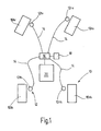
- FIG. 1 shows a block diagram of a system according to the invention.
- Each wheel 10 is assigned a wheel speed sensor device 12.
- the reference numeral 10 of the wheels is provided to identify the position of the respective wheel on the vehicle with two code letters. 1 means left, right r, v front and h back. In the same way, the wheel 10 associated sensor devices 12 are marked.
- the sensor devices 12 are connected via data lines 14 to a data processing device 16.
- the data processing device 16 is in turn connected to a memory device 18 and an ASR system 20 for data transmission.
- the front wheels 101v and 10rv are steerable in the illustrated example, the rear wheels 101h and 101r are not.
- the sensor devices 12 detect the rotational speeds of their respective associated wheels 10 and deliver corresponding signals via data lines 14 to the data processing device 16.
- the data processing device 16 calculates from the wheel speeds of the non-driven wheels a mean translational wheel speed of the non-driven wheels.
- the data processing device 16 additionally reads vehicle geometry data from the memory device 18 and uses this geometry data and based on wheel speed information to determine a current yaw rate, a curve radius of the currently traversed curved path, a lateral acceleration and a geometric slip of the inside and outside wheels.
- the above-mentioned calculated quantities are finally stored by the data processing device 16 in the memory device 18, where they are available to the ASR system 20.
- the sensor devices 12 may be part of the ASR system, which usually has wheel speed sensors for slip-based control anyway. Likewise the data processing device 16 and the memory device 18 be part of the ASR system 20.
- the device 20 may also be another slip-based system for controlling drivability, such as an ESP or anti-lock brake system.
- another slip-based system for controlling drivability such as an ESP or anti-lock brake system.
- step S01 wheel speeds at each wheel of the vehicle are detected and forwarded to the data processing device 16.
- a mean wheel speed of the non-driven wheels v is not driven__ driven in step S02 first by averaging.
- the translatory wheel speed results from the detected wheel speed, multiplied by the wheel radius and the factor 2 ⁇ .
- n not_driven_ki / ka is the wheel speeds of the non-driven inside (ki) or outside (ka) wheels and r Rad is the radius of the wheels.
- a current lateral acceleration a across the vehicle is calculated.
- the determination of the lateral acceleration can be omitted. Then, the illustrated method may proceed without step S05.
- the steps S04 and S05 in the illustrated method can be dispensed with.
- yaw rate and lateral acceleration can be obtained in a simple manner only from a detection and processing of wheel speeds and used for subsequent control methods, these variables are determined in a preferred embodiment of the method.
- V not _ driven_curves is the translational speed of the non-driven inside wheel, that is, the front wheel in a rear-wheel drive and the rear wheel in a front-wheel drive vehicle. This applies analogously to the outside wheels.
- v front wheel or v rear wheel With v front wheel or v rear wheel , the translational speed of the front wheel or rear wheel is designated.
- the index suffix "ki” or “ka” indicates which front wheel speed and which rear wheel speed of the inside or the outside of the wheel is to be used. The equations used are combined below with Fig. 3 be explained in more detail.
- step S09 the values of the wheel slip of the inside-wheel pair and the outside-of-the-outside wheel pair previously obtained in step S07 are corrected by the geometric wheel slip values obtained in step S08.
- step S10 Memory device forwarded where they are available to the ASR system for consideration in a control of driving behavior.
- FIG. 3 For example, the right front wheel 12rv and the right rear wheel 12rh of FIG. 1 shown as curve-inner wheel pair in a curve in a right turn.
- the distance of the front wheel 12rv from the rear wheel 12rh corresponds to the wheelbase L.
- the front wheel 12rv is turned by a steering angle ⁇ to the right.
- the wheels obey, as usual in Achsschenkellenkung, the Ackermann condition, that is, the extended rotational axes 22 of the right front wheel 12rv and 24 of the right rear wheel 12rh intersect in the instantaneous center M on the extension of the rear axle.
- the vehicle turns instantaneously around this instantaneous pole M.
- the right rear wheel 12rh has a distance R from the instantaneous pole M
- the right front wheel 12rv has a larger distance R + ⁇ R than ⁇ R
- the wheels roll at different speeds on concentric circular trajectories 26 and 28 with the instantaneous center point M as the center.
- the curve radius can be determined as indicated above.
- the translational wheel center speed results for each wheel from the product of the distance of the respective wheel to the instantaneous center M and the yaw rate ⁇ .
- ⁇ geom_FA R + .DELTA.R ⁇ ⁇ - R ⁇ ⁇ R ⁇ ⁇ ,
- ⁇ geom_HA R + .DELTA.R ⁇ ⁇ - R ⁇ ⁇ R + .DELTA.R ⁇ ⁇
- ⁇ geom_HA 1 - 1 1 + 1 2 ⁇ L ⁇ ⁇ v H int errad 2
Landscapes
- Engineering & Computer Science (AREA)
- Transportation (AREA)
- Mechanical Engineering (AREA)
- Chemical & Material Sciences (AREA)
- Combustion & Propulsion (AREA)
- Regulating Braking Force (AREA)
- Control Of Driving Devices And Active Controlling Of Vehicle (AREA)
- Arrangement And Driving Of Transmission Devices (AREA)
- Steering Control In Accordance With Driving Conditions (AREA)
Abstract
Claims (13)
- Système de commande et/ou de régulation du comportement de roulage d'un véhicule automobile qui présente au moins deux roues, le système présentant
au moins un dispositif de détection (12) qui saisit la vitesse de rotation d'au moins deux roues (10) et un dispositif (16) de traitement de données qui détermine au moins une équation de déplacement d'au moins deux roues (10) sur la base de la vitesse de rotation saisie sur les roues,
le dispositif (16) de traitement de données déterminant en outre sur la base de la ou des équations de déplacement définies le patinage géométrique des roues en tant que grandeur de déplacement du véhicule automobile en virage et corrigeant avec cette dernière le patinage des roues calculé à partir des vitesses de rotation saisies sur les roues,
caractérisé en ce que
le dispositif (16) de traitement de données détermine le patinage géométrique des roues pour le côté du véhicule situé à l'intérieur du virage et le côté du véhicule situé à l'extérieur du virage sur la base de l'empattement des roues du véhicule et de la distance entre la roue située à l'intérieur du virage et un pôle instantané du véhicule automobile ou sur la base de l'empattement des roues du véhicule automobile, de la vitesse de lacet du véhicule automobile et de la vitesse de rotation d'au moins une roue située sur le côté du véhicule situé à l'intérieur du virage ou sur le côté du véhicule situé à l'extérieur du virage. - Système selon la revendication 1, caractérisé en ce qu'un dispositif de détection (12) est associé respectivement à au moins deux roues (10) situées l'une en face de l'autre dans la direction transversale par rapport au véhicule, de préférence également à au moins deux roues (10) disposées l'une derrière l'autre dans le sens de la longueur du véhicule et de façon particulièrement préférable à chaque roue (10) du véhicule.
- Système selon l'une des revendications précédentes, caractérisé en ce que le ou les dispositifs de détection (12) sont des dispositifs de détection sur bandage de roue et/ou des dispositifs de détection sur palier de roue.
- Système selon l'une des revendications précédentes, caractérisé en ce qu'il comporte un dispositif de mémoire (18) qui conserve en mémoire des valeurs saisies et/ou des valeurs déterminées et qui conserve également des données prédéterminées de la géométrie du véhicule.
- Système selon l'une des revendications précédentes, caractérisé en ce que le dispositif (16) de traitement de données délivre un signal de réglage en fonction de la grandeur déterminée du déplacement en virage et en ce que le système comporte en outre un dispositif de réglage (20) qui agit sur l'état de fonctionnement du véhicule automobile en fonction du signal de réglage.
- Système selon l'une des revendications précédentes, caractérisé en ce que le dispositif (16) de traitement de données et/ou le dispositif de réglage (20) sont associés à un dispositif (20) de commande et/ou de régulation du comportement de roulage du véhicule automobile, par exemple un système ASR (20), un système antiblocage ou un système ESP, ou sont ces systèmes.
- Système selon l'une des revendications précédentes, caractérisé en ce que le dispositif (20) de commande et/ou de régulation du comportement de roulage d'un véhicule automobile sélectionne des algorithmes de commande et/ou de régulation en fonction de la ou des grandeurs de déplacement en virage qui ont été déterminées.
- Système selon l'une des revendications précédente, caractérisé en ce que le dispositif de réglage (20) est associé à un système ASR (20) qui commute entre une régulation prioritaire de la traction et une régulation prioritaire de la stabilité de roulage en fonction du rayon déterminé pour le virage, de préférence en tenant compte de la vitesse du véhicule.
- Procédé de commande et/ou de régulation du comportement de roulage d'un véhicule automobile qui présente au moins deux roues, le procédé comportant les étapes qui consistent à :- saisir la vitesse de rotation d'au moins deux roues (S01),- déterminer au moins une équation de déplacement d'au moins deux roues en fonction des vitesses de rotation saisies sur les roues (S03),- déterminer un patinage géométrique des roues (S08) en tant que grandeur de déplacement du véhicule automobile en virage sur la base de l'équation définie de déplacement (S04, S05, S06, S08) et- corriger du patinage géométrique déterminé le patinage des roues ainsi déterminé en virage (S09), caractérisé en ce quele patinage géométrique des roues est déterminé pour le côté du véhicule situé à l'intérieur du virage et le côté du véhicule situé à l'extérieur du virage sur la base de l'empattement des roues du véhicule et de la distance entre la roue située à l'intérieur du virage et un pôle instantané du véhicule automobile ou sur la base de l'empattement des roues du véhicule automobile, de la vitesse de lacet du véhicule automobile et de la vitesse de rotation d'au moins une roue située sur le côté du véhicule situé à l'intérieur du virage ou sur le côté du véhicule situé à l'extérieur du virage.
- Procédé selon la revendication 9, caractérisé en ce que l'étape (S03) de détermination de l'équation de déplacement comporte la détermination de la différence entre les vitesses de rotation de deux roues (S03).
- Procédé selon les revendications 9 ou 10, caractérisé en ce que la vitesse de lacet est déterminée sur la base de la différence de vitesse de roues situées essentiellement l'une en face de l'autre dans le sens transversal du véhicule, de l'écart entre les roues du véhicule, de l'empattement des roues du véhicule et des vitesses de rotation des roues non motrices.
- Procédé selon l'une des revendications 9 à 11, caractérisé en ce que le rayon du virage et l'accélération transversale sont déterminés à l'aide des vitesses de rotation des roues non motrices et de la vitesse de lacet.
- Procédé selon l'une des revendications 9 à 12, caractérisé en ce que le patinage géométrique déterminé pour les roues situées à l'extérieur du virage est pris en compte dans le calcul du seuil de patinage de dispositifs de commande et/ou de régulation travaillant sur la base du patinage, par exemple un système antiblocage et/ou un système ASR.
Applications Claiming Priority (3)
| Application Number | Priority Date | Filing Date | Title |
|---|---|---|---|
| DE10065774 | 2000-12-30 | ||
| DE10065774 | 2000-12-30 | ||
| PCT/DE2001/004908 WO2002053433A1 (fr) | 2000-12-30 | 2001-12-22 | Systeme et procede de commande et/ou de regulation du comportement de conduite d'un vehicule automobile |
Publications (2)
| Publication Number | Publication Date |
|---|---|
| EP1347904A1 EP1347904A1 (fr) | 2003-10-01 |
| EP1347904B1 true EP1347904B1 (fr) | 2012-08-22 |
Family
ID=7669461
Family Applications (1)
| Application Number | Title | Priority Date | Filing Date |
|---|---|---|---|
| EP01991681A Expired - Lifetime EP1347904B1 (fr) | 2000-12-30 | 2001-12-22 | Systeme et procede de commande et/ou de regulation du comportement de conduite d'un vehicule automobile |
Country Status (6)
| Country | Link |
|---|---|
| US (1) | US6810317B2 (fr) |
| EP (1) | EP1347904B1 (fr) |
| JP (1) | JP4603238B2 (fr) |
| KR (1) | KR20020081359A (fr) |
| DE (1) | DE10160069A1 (fr) |
| WO (1) | WO2002053433A1 (fr) |
Families Citing this family (13)
| Publication number | Priority date | Publication date | Assignee | Title |
|---|---|---|---|---|
| DE10328979B4 (de) * | 2003-06-27 | 2021-07-22 | Robert Bosch Gmbh | Verfahren zur Koordination eines Fahrdynamikregelungssystems mit einem aktiven Normalkraftverstellsystem |
| DE102004037616A1 (de) * | 2004-08-03 | 2006-03-16 | Volkswagen Ag | Vorrichtung und Verfahren zur Erzeugung eines Gewichtssignals |
| US7966113B2 (en) * | 2005-08-25 | 2011-06-21 | Robert Bosch Gmbh | Vehicle stability control system |
| US7641014B2 (en) * | 2006-01-31 | 2010-01-05 | Robert Bosch Gmbh | Traction control system and method |
| CA2722654C (fr) * | 2008-05-05 | 2015-06-30 | Crown Equipment Corporation | Controle du patinage pour un vehicule de manipulation de materiaux |
| DE102010004113B4 (de) * | 2010-01-07 | 2014-11-20 | Continental Automotive Gmbh | Verfahren und Vorrichtung zur Ermittlung eines maximalen Reibungsbeiwerts μmax zwischen einem Reifen und einem Untergrund |
| USD689794S1 (en) | 2011-03-21 | 2013-09-17 | Polaris Industries Inc. | Three wheeled vehicle |
| US8695746B2 (en) | 2011-03-21 | 2014-04-15 | Polaris Industries Inc. | Three wheeled vehicle |
| DE102013005991B4 (de) * | 2012-12-28 | 2020-01-23 | Bomag Gmbh | Verfahren und Vorrichtung zur Ermittlung des Lenkwinkels einer richtungssteuerbaren Maschine |
| US20150102955A1 (en) * | 2013-10-14 | 2015-04-16 | GM Global Technology Operations LLC | Measurement association in vehicles |
| DE102014210062A1 (de) * | 2014-05-27 | 2015-12-03 | Continental Teves Ag & Co. Ohg | Verfahren zur Einstellung einer Schlupfschwelle und Fahrdynamik-Regeleinrichtung |
| US9751403B2 (en) | 2014-08-12 | 2017-09-05 | Honda Motor Co., Ltd. | Differential assembly and speed sensor mounting arrangement therefor |
| USD1032429S1 (en) | 2021-12-06 | 2024-06-25 | Polaris Industries Inc. | Vehicle bonnet |
Family Cites Families (15)
| Publication number | Priority date | Publication date | Assignee | Title |
|---|---|---|---|---|
| DE3935588A1 (de) * | 1989-10-23 | 1991-04-25 | Forschungsgesellschaft Kraftfa | Verfahren zur gewaehrleistung der fahrstabilitaet von kraftfahrzeugen |
| DE4128087A1 (de) | 1991-08-24 | 1993-02-25 | Bosch Gmbh Robert | Bremsdruckregelanlage fuer ein fahrzeug |
| DE4201675C1 (fr) | 1992-01-23 | 1993-05-19 | Mercedes-Benz Aktiengesellschaft, 7000 Stuttgart, De | |
| JP2964875B2 (ja) * | 1994-07-19 | 1999-10-18 | 株式会社デンソー | アンチスキッド制御装置 |
| JPH08188138A (ja) * | 1995-01-13 | 1996-07-23 | Nissan Motor Co Ltd | アンチスキッド制御装置 |
| DE19548564A1 (de) | 1995-12-23 | 1997-06-26 | Bosch Gmbh Robert | Verfahren und Vorrichtung zur Antriebsschlupfregelung |
| JPH09207745A (ja) * | 1996-01-30 | 1997-08-12 | Nissan Motor Co Ltd | アンチスキッド制御装置 |
| JPH09226559A (ja) * | 1996-02-23 | 1997-09-02 | Toyota Motor Corp | 制駆動力制御用基準車輪速度演算装置 |
| DE19724955C2 (de) | 1997-06-12 | 1999-04-15 | Siemens Ag | Verfahren zum Ermitteln der Giergeschwindigkeit eines Fahrzeugs |
| DE19744725A1 (de) * | 1997-10-10 | 1999-04-15 | Itt Mfg Enterprises Inc | Verfahren zum Bestimmen von Zustandsgrößen eines Kraftfahrzeuges |
| DE19750501A1 (de) | 1997-11-14 | 1999-05-20 | Itt Mfg Enterprises Inc | Verfahren zur Verbesserung des Regelverhaltens eines ASR-Systems |
| DE19812237C1 (de) * | 1998-03-20 | 1999-09-23 | Daimler Chrysler Ag | Verfahren zur Fahrdynamik-Regelung an einem Straßenfahrzeug |
| DE19933084B4 (de) * | 1999-07-15 | 2014-01-09 | Robert Bosch Gmbh | Verfahren und Vorrichtung zur Steuerung des Schlupfes eines Fahrzeugrades |
| DE19950477A1 (de) * | 1999-10-20 | 2001-04-26 | Bosch Gmbh Robert | Verfahren und System zur Regelung des Verhaltens eines Fahrzeugs bei einer Bewegung |
| DE19958772B4 (de) * | 1999-12-07 | 2011-07-21 | Robert Bosch GmbH, 70469 | Verfahren und Vorrichtung zur Antriebsschlupfregelung (ASR) eines Kraftfahrzeugs in Abhängigkeit von Kurvenradius und Querbeschleunigung |
-
2001
- 2001-12-06 DE DE10160069A patent/DE10160069A1/de not_active Withdrawn
- 2001-12-22 EP EP01991681A patent/EP1347904B1/fr not_active Expired - Lifetime
- 2001-12-22 US US10/220,512 patent/US6810317B2/en not_active Expired - Lifetime
- 2001-12-22 KR KR1020027011198A patent/KR20020081359A/ko not_active Application Discontinuation
- 2001-12-22 WO PCT/DE2001/004908 patent/WO2002053433A1/fr active Application Filing
- 2001-12-22 JP JP2002554563A patent/JP4603238B2/ja not_active Expired - Fee Related
Also Published As
| Publication number | Publication date |
|---|---|
| WO2002053433A1 (fr) | 2002-07-11 |
| EP1347904A1 (fr) | 2003-10-01 |
| DE10160069A1 (de) | 2002-09-19 |
| JP2004516984A (ja) | 2004-06-10 |
| KR20020081359A (ko) | 2002-10-26 |
| JP4603238B2 (ja) | 2010-12-22 |
| US6810317B2 (en) | 2004-10-26 |
| US20030176961A1 (en) | 2003-09-18 |
Similar Documents
| Publication | Publication Date | Title |
|---|---|---|
| EP2864164B1 (fr) | Procédé pour faire fonctionner un dispositif de régulation du glissement des roues avec des vitesses de roue compensées | |
| EP1387787B1 (fr) | Procede et systeme pour reguler le comportement routier d'un vehicule | |
| EP2788244B1 (fr) | Procédé de stabilisation de conduite, dispositif de stabilisation de conduite et véhicule équipé de celui-ci | |
| EP1807300B1 (fr) | Procede et dispositif permettant d'assister un serveur de vehicule lors de la stabilisation d'un vehicule | |
| DE4327492C1 (de) | Verfahren zur Reifendruckwarnung | |
| EP1826099B1 (fr) | Procédé destiné à la détermination du rapport de direction d'un véhicule | |
| EP1347904B1 (fr) | Systeme et procede de commande et/ou de regulation du comportement de conduite d'un vehicule automobile | |
| DE4418070C1 (de) | Verfahren zum Abgleichen der Raddrehzahlen für ein Kraftfahrzeug | |
| EP0611348B1 (fr) | Procede d'identification de virage | |
| DE19615311B4 (de) | Verfahren und Vorrichtung zur Regelung einer die Fahrzeugbewegung repräsentierenden Bewegungsgröße | |
| EP2694315B1 (fr) | Système d'assistance au stationnement, basé sur la direction de déplacement du véhicule | |
| DE102018107612A1 (de) | Kraftfahrzeug mit Hinterradlenkung und Torque-Vectoring auf der Hinterradachse | |
| EP1480855B1 (fr) | Procede et dispositif permettant de detecter les roues soulevees d'un vehicule | |
| EP2165895A2 (fr) | Appareil de contrôle des mouvements pour véhicule | |
| EP0979771A2 (fr) | Procédé pour influencer les caractéristiques de roulis des véhicules automobiles | |
| DE102012222197B4 (de) | Verfahren zur Drehmomentaufteilung eines Antriebsdrehmoments auf eine Primärachse und eine Sekundärachse eines Kraftfahrzeugs, Verfahren zur Drehmomentaufteilung eines Achsdrehmoments auf ein linkes und ein rechtes Rad einer gemeinsamen Achse eines Kraftfahrzeugs und Kraftfahrzeug, umfassend ein Parkassistenzsystem mit Querführung | |
| EP3810464B1 (fr) | Procédé de détermination d'un rayon de roue corrigé sur la base du taux de lacet mesuré | |
| EP1640311A2 (fr) | Méthode pour prévenir le renversement de véhicules dirigés par la roue arrière, en particulier de véhicules industriels | |
| DE102013009399B4 (de) | Verfahren zur Erkennung einer kritischen Fahrsituation eines Fahrzeugs | |
| DE102017114494A1 (de) | Steer-by-Wire-Lenksystem mit Torque-Vectoring und integrierter Anti-Schlupf-Regelung | |
| DE102016014325A1 (de) | Verfahren zur Anpassung eines Parkassistenzsystems an ein Fahrzeug | |
| EP1607306B1 (fr) | Procédé et dispositif pour l'assistance de la direction dans situations de sous-virage | |
| EP1194304B1 (fr) | Procede et dispositif pour elaborer une table de valeurs de correction, determiner une valeur d'essai et detecter une perte de pression dans un pneu de roue | |
| EP1255653B1 (fr) | Procede et dispositif de detection d'une perte de pression sur les pneumatiques d'un vehicule, avec controle de plausibilite | |
| EP4161810B1 (fr) | Axe et méthode de compensation de décélération |
Legal Events
| Date | Code | Title | Description |
|---|---|---|---|
| PUAI | Public reference made under article 153(3) epc to a published international application that has entered the european phase |
Free format text: ORIGINAL CODE: 0009012 |
|
| 17P | Request for examination filed |
Effective date: 20030730 |
|
| AK | Designated contracting states |
Kind code of ref document: A1 Designated state(s): AT BE CH CY DE DK ES FI FR GB GR IE IT LI LU MC NL PT SE TR |
|
| RBV | Designated contracting states (corrected) |
Designated state(s): DE FR GB |
|
| 17Q | First examination report despatched |
Effective date: 20071213 |
|
| REG | Reference to a national code |
Ref country code: DE Ref legal event code: R079 Ref document number: 50116162 Country of ref document: DE Free format text: PREVIOUS MAIN CLASS: B60T0008000000 Ipc: B60T0008175000 |
|
| GRAP | Despatch of communication of intention to grant a patent |
Free format text: ORIGINAL CODE: EPIDOSNIGR1 |
|
| RIC1 | Information provided on ipc code assigned before grant |
Ipc: B60T 8/175 20060101AFI20120426BHEP |
|
| GRAS | Grant fee paid |
Free format text: ORIGINAL CODE: EPIDOSNIGR3 |
|
| GRAA | (expected) grant |
Free format text: ORIGINAL CODE: 0009210 |
|
| AK | Designated contracting states |
Kind code of ref document: B1 Designated state(s): DE FR GB |
|
| REG | Reference to a national code |
Ref country code: GB Ref legal event code: FG4D Free format text: NOT ENGLISH |
|
| REG | Reference to a national code |
Ref country code: DE Ref legal event code: R096 Ref document number: 50116162 Country of ref document: DE Effective date: 20121018 |
|
| PLBE | No opposition filed within time limit |
Free format text: ORIGINAL CODE: 0009261 |
|
| STAA | Information on the status of an ep patent application or granted ep patent |
Free format text: STATUS: NO OPPOSITION FILED WITHIN TIME LIMIT |
|
| 26N | No opposition filed |
Effective date: 20130523 |
|
| REG | Reference to a national code |
Ref country code: DE Ref legal event code: R097 Ref document number: 50116162 Country of ref document: DE Effective date: 20130523 |
|
| PGFP | Annual fee paid to national office [announced via postgrant information from national office to epo] |
Ref country code: GB Payment date: 20131217 Year of fee payment: 13 |
|
| PGFP | Annual fee paid to national office [announced via postgrant information from national office to epo] |
Ref country code: FR Payment date: 20131213 Year of fee payment: 13 |
|
| GBPC | Gb: european patent ceased through non-payment of renewal fee |
Effective date: 20141222 |
|
| REG | Reference to a national code |
Ref country code: FR Ref legal event code: ST Effective date: 20150831 |
|
| PG25 | Lapsed in a contracting state [announced via postgrant information from national office to epo] |
Ref country code: GB Free format text: LAPSE BECAUSE OF NON-PAYMENT OF DUE FEES Effective date: 20141222 |
|
| PG25 | Lapsed in a contracting state [announced via postgrant information from national office to epo] |
Ref country code: FR Free format text: LAPSE BECAUSE OF NON-PAYMENT OF DUE FEES Effective date: 20141231 |
|
| PGFP | Annual fee paid to national office [announced via postgrant information from national office to epo] |
Ref country code: DE Payment date: 20160224 Year of fee payment: 15 |
|
| REG | Reference to a national code |
Ref country code: DE Ref legal event code: R119 Ref document number: 50116162 Country of ref document: DE |
|
| PG25 | Lapsed in a contracting state [announced via postgrant information from national office to epo] |
Ref country code: DE Free format text: LAPSE BECAUSE OF NON-PAYMENT OF DUE FEES Effective date: 20170701 |