EP1347904B1 - System and method for controlling and/or regulating the handling characteristics of a motor vehicle - Google Patents
System and method for controlling and/or regulating the handling characteristics of a motor vehicle Download PDFInfo
- Publication number
- EP1347904B1 EP1347904B1 EP01991681A EP01991681A EP1347904B1 EP 1347904 B1 EP1347904 B1 EP 1347904B1 EP 01991681 A EP01991681 A EP 01991681A EP 01991681 A EP01991681 A EP 01991681A EP 1347904 B1 EP1347904 B1 EP 1347904B1
- Authority
- EP
- European Patent Office
- Prior art keywords
- wheel
- wheels
- vehicle
- motor vehicle
- determined
- Prior art date
- Legal status (The legal status is an assumption and is not a legal conclusion. Google has not performed a legal analysis and makes no representation as to the accuracy of the status listed.)
- Expired - Lifetime
Links
Images


Classifications
-
- B—PERFORMING OPERATIONS; TRANSPORTING
- B60—VEHICLES IN GENERAL
- B60T—VEHICLE BRAKE CONTROL SYSTEMS OR PARTS THEREOF; BRAKE CONTROL SYSTEMS OR PARTS THEREOF, IN GENERAL; ARRANGEMENT OF BRAKING ELEMENTS ON VEHICLES IN GENERAL; PORTABLE DEVICES FOR PREVENTING UNWANTED MOVEMENT OF VEHICLES; VEHICLE MODIFICATIONS TO FACILITATE COOLING OF BRAKES
- B60T8/00—Arrangements for adjusting wheel-braking force to meet varying vehicular or ground-surface conditions, e.g. limiting or varying distribution of braking force
- B60T8/17—Using electrical or electronic regulation means to control braking
- B60T8/175—Brake regulation specially adapted to prevent excessive wheel spin during vehicle acceleration, e.g. for traction control
-
- B—PERFORMING OPERATIONS; TRANSPORTING
- B60—VEHICLES IN GENERAL
- B60T—VEHICLE BRAKE CONTROL SYSTEMS OR PARTS THEREOF; BRAKE CONTROL SYSTEMS OR PARTS THEREOF, IN GENERAL; ARRANGEMENT OF BRAKING ELEMENTS ON VEHICLES IN GENERAL; PORTABLE DEVICES FOR PREVENTING UNWANTED MOVEMENT OF VEHICLES; VEHICLE MODIFICATIONS TO FACILITATE COOLING OF BRAKES
- B60T8/00—Arrangements for adjusting wheel-braking force to meet varying vehicular or ground-surface conditions, e.g. limiting or varying distribution of braking force
-
- B—PERFORMING OPERATIONS; TRANSPORTING
- B60—VEHICLES IN GENERAL
- B60T—VEHICLE BRAKE CONTROL SYSTEMS OR PARTS THEREOF; BRAKE CONTROL SYSTEMS OR PARTS THEREOF, IN GENERAL; ARRANGEMENT OF BRAKING ELEMENTS ON VEHICLES IN GENERAL; PORTABLE DEVICES FOR PREVENTING UNWANTED MOVEMENT OF VEHICLES; VEHICLE MODIFICATIONS TO FACILITATE COOLING OF BRAKES
- B60T2201/00—Particular use of vehicle brake systems; Special systems using also the brakes; Special software modules within the brake system controller
- B60T2201/16—Curve braking control, e.g. turn control within ABS control algorithm
Definitions
- the present invention relates to a system for controlling and / or regulating the driving behavior of a motor vehicle having at least two wheels, comprising: at least one sensor device, which detects wheel speeds of at least two wheels, and a data processing device, which according to the detected wheel speeds at least one movement relationship of at least two wheels determined to each other, wherein the data processing device further determines according to the at least one specific movement relationship a geometric wheel slip as cornering motion size of the motor vehicle and corrected with this one calculated from the detected wheel speeds wheel slip.
- the present invention further relates to a method for controlling and / or regulating the driving behavior of a motor vehicle having at least two wheels, preferably for execution by the system according to the invention, comprising the steps of: detecting wheel speeds of at least two wheels, and determining at least one movement relationship of at least two wheels in accordance with the detected wheel speeds, determining a geometric wheel slip as cornering motion size of the motor vehicle in accordance with the determined movement relationship and correcting a determined wheel slip when cornering around the determined geometric wheel slip.
- Ackermann condition defines the position of the individual wheels of a motor vehicle when cornering and requires that the extended axes of rotation of all wheels of a motor vehicle intersect at a point. This point is then the instantaneous center around which the vehicle turns. Since the rear wheels of a motor vehicle are generally not steerable, the instantaneous pole is usually located on an extension of the axis of rotation of the substantially coaxially arranged rear wheels.
- All wheels of a vehicle then have a different distance from the instantaneous center and therefore have different wheel speeds when cornering or wheel speeds, from which devices which determine the wheel slip on the basis of a comparison of wheel speeds of different wheels, determine an apparent wheel slip, without this actually exists.
- the document DE 197 50 501 A discloses a system and a method for controlling and / or regulating the driving behavior of a motor vehicle according to the preamble of claims 1 and 9.
- the document EP 0 552 456 A discloses a simple correction of wheel slip when cornering based on an average wheel speed, or wheel speed difference.
- the object of the present invention is to improve a correction of the wheel slip when cornering by a more accurate determination of the geometric wheel slip.
- This system allows a very accurate determination of the at least one cornering motion variable with low sensor complexity. In this case, only wheel speeds are detected and the determination of the at least one cornering movement quantity is thus based on the actual conditions prevailing between the driving surface and the wheels.
- it is possible, for example, to carry out methods for controlling and / or regulating the driving behavior of the vehicle with greater accuracy than hitherto on the basis of the precisely determined cornering motion variable.
- a suitable movement relationship is, for example, a rotational speed difference between two wheels, preferably between two wheels arranged at a distance from one another in the vehicle transverse direction, for example between two front wheels and / or between two guard wheels. From this speed difference can be directly derived that the vehicle is cornering.
- the speed difference of the steered wheels in the engaged state may be different from the speed difference of the steered wheels. Due to the proportionality between the wheel speed and the translatory wheel speed, what has been said above and below applies both to rotational speeds and to translatory wheel speeds, that is to say to the speed of a wheel center.
- a yaw rate and / or a turning radius and / or a lateral acceleration and / or a geometric slip of the vehicle can be determined as a turning movement quantity.
- geometric slip is the previously explained, occurring due to compliance with the Ackermann condition slip apparent referred to.
- At least two wheels lying opposite each other in the vehicle transverse direction preferably additionally at least two wheels arranged behind one another in the vehicle longitudinal direction, particularly preferably each wheel of the vehicle, can be assigned one sensor device each.
- the more wheels one associated with such sensor device the more accurately the at least one cornering movement quantity can be determined.
- a suitable sensor device is a tire sensor device and / or a wheel bearing sensor device.
- the advantage of these sensor devices is that they can detect wheel speeds directly on the wheel and, moreover, they are still capable of detecting additional information about forces acting between the wheel and the road surface.
- the detection of the wheel speed is also conceivable with a conventional speed sensor, consisting for example of impulse ring and sensor, as used for example in anti-lock braking systems.
- An advantage of the invention in this context is that only a single type of sensor, namely a wheel speed detecting sensor, sufficient.
- the system may comprise a memory device.
- predetermined vehicle geometry data are stored in this memory device, on the basis of which a determination of the at least one cornering movement variable can be performed together with the detected wheel speeds.
- the data processing device performs correction of wheel slip in accordance with the determined at least one turning movement amount.
- the data processing device to increase traffic safety in accordance with the determined cornering motion size output a control signal
- the system advantageously further comprises an actuating device which influences an operating state of the motor vehicle in accordance with the control signal. Thereafter, about a regulation of the vehicle speed in accordance with the determined yaw rate and / or the determined lateral acceleration take place.
- the number of components required for realizing the system according to the invention can be kept low by the fact that the data processing device and / or the adjusting device of a device for controlling and / or regulating the driving behavior of a motor vehicle, such as an ASR, an anti-lock or ESP System, is assigned respectively.
- An improvement of the control and / or the regulation of the driving behavior by a corresponding device can take place in that the device for controlling and / or regulating the driving behavior of a motor vehicle as a function of the determined at least one cornering motion variable control and / or control algorithms selects.
- the adjusting device can be assigned to an ASR system or be part of an ASR system, which switches between traction-prioritized and driving-stability-prioritized control as a function of the determined curve radius, preferably taking into account the vehicle speed.
- the adjusting device can be assigned to an ASR system or be part of an ASR system, which switches between traction-prioritized and driving-stability-prioritized control as a function of the determined curve radius, preferably taking into account the vehicle speed.
- the adjusting device can be assigned to an ASR system or be part of an ASR system, which switches between traction-prioritized and driving-stability-prioritized control as a function of the determined curve radius, preferably taking into account the vehicle speed.
- small curve radii it is possible to control such that the highest possible traction is achieved, while at higher curve radii - and optionally at high vehicle speeds - a high driving stability is preferred.
- the advantages of the invention are achieved by a system for controlling and / or regulating the driving behavior of a motor vehicle having at least one wheel, wherein the geometrical slip and / or the curve radius and / or the yaw rate of the vehicle is determined from the detected wheel movement behavior.
- the present invention further comprises a step of determining at least one turning movement amount of the vehicle in accordance with the determined moving relationship.
- the method according to the invention also achieves the advantages mentioned above in connection with the system according to the invention, for which reason reference is expressly made to the description of the system according to the invention for a supplementary explanation of the method.
- a speed difference between two wheels is determined as the movement relationship.
- This is preferably a speed difference between two spaced apart in the vehicle transverse direction wheels, such as between the front wheels and / or between the rear wheels.
- a particularly accurate determination of the at least one cornering motion variable is made possible by the fact that the wheel speed of as many, preferably all, vehicle wheels is detected.
- a yaw rate of the vehicle can be calculated particularly simply from a speed difference between two wheels arranged at a distance from one another in the vehicle transverse direction as the cornering motion variable.
- only knowledge of the geometric conditions on the vehicle are required. These can be stored in a memory device.
- a curve radius can also be determined as a curve movement quantity.
- sufficient knowledge of a mean speed of non-driven wheels and the yaw rate, wherein the average speed of non-driven wheels from corresponding wheel speeds of these wheels can be calculated by averaging.
- a determination of the curve radius directly from the speeds of the vehicle wheels taking into account the Ackermann condition or the gauge conceivable.
- a lateral acceleration of the vehicle can be determined as a turning movement amount.
- the geometric slippage of the vehicle caused by compliance with the Ackermann condition when cornering can be determined as a curve movement quantity.
- variables derived from the wheel speeds such as vehicle speed and wheel slip, can be correspondingly corrected and determined more accurately.
- the determined geometric wheel slip of the inside wheels can be taken into account advantageously in the slip threshold calculation of slip-based control and / or regulating devices and thereby the accuracy of the control and / or the control can be increased.
- Such devices are for example anti-lock, ASR and / or ESP systems.
- the geometric slip of the outside wheels can be used as a measure of the possible lateral guidance of the vehicle when cornering and can also be taken into account in a so-called RAKA determination.
- RAKA stands for "control deviation outside the curve”.
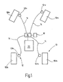
- FIG. 1 shows a block diagram of a system according to the invention.
- Each wheel 10 is assigned a wheel speed sensor device 12.
- the reference numeral 10 of the wheels is provided to identify the position of the respective wheel on the vehicle with two code letters. 1 means left, right r, v front and h back. In the same way, the wheel 10 associated sensor devices 12 are marked.
- the sensor devices 12 are connected via data lines 14 to a data processing device 16.
- the data processing device 16 is in turn connected to a memory device 18 and an ASR system 20 for data transmission.
- the front wheels 101v and 10rv are steerable in the illustrated example, the rear wheels 101h and 101r are not.
- the sensor devices 12 detect the rotational speeds of their respective associated wheels 10 and deliver corresponding signals via data lines 14 to the data processing device 16.
- the data processing device 16 calculates from the wheel speeds of the non-driven wheels a mean translational wheel speed of the non-driven wheels.
- the data processing device 16 additionally reads vehicle geometry data from the memory device 18 and uses this geometry data and based on wheel speed information to determine a current yaw rate, a curve radius of the currently traversed curved path, a lateral acceleration and a geometric slip of the inside and outside wheels.
- the above-mentioned calculated quantities are finally stored by the data processing device 16 in the memory device 18, where they are available to the ASR system 20.
- the sensor devices 12 may be part of the ASR system, which usually has wheel speed sensors for slip-based control anyway. Likewise the data processing device 16 and the memory device 18 be part of the ASR system 20.
- the device 20 may also be another slip-based system for controlling drivability, such as an ESP or anti-lock brake system.
- another slip-based system for controlling drivability such as an ESP or anti-lock brake system.
- step S01 wheel speeds at each wheel of the vehicle are detected and forwarded to the data processing device 16.
- a mean wheel speed of the non-driven wheels v is not driven__ driven in step S02 first by averaging.
- the translatory wheel speed results from the detected wheel speed, multiplied by the wheel radius and the factor 2 ⁇ .
- n not_driven_ki / ka is the wheel speeds of the non-driven inside (ki) or outside (ka) wheels and r Rad is the radius of the wheels.
- a current lateral acceleration a across the vehicle is calculated.
- the determination of the lateral acceleration can be omitted. Then, the illustrated method may proceed without step S05.
- the steps S04 and S05 in the illustrated method can be dispensed with.
- yaw rate and lateral acceleration can be obtained in a simple manner only from a detection and processing of wheel speeds and used for subsequent control methods, these variables are determined in a preferred embodiment of the method.
- V not _ driven_curves is the translational speed of the non-driven inside wheel, that is, the front wheel in a rear-wheel drive and the rear wheel in a front-wheel drive vehicle. This applies analogously to the outside wheels.
- v front wheel or v rear wheel With v front wheel or v rear wheel , the translational speed of the front wheel or rear wheel is designated.
- the index suffix "ki” or “ka” indicates which front wheel speed and which rear wheel speed of the inside or the outside of the wheel is to be used. The equations used are combined below with Fig. 3 be explained in more detail.
- step S09 the values of the wheel slip of the inside-wheel pair and the outside-of-the-outside wheel pair previously obtained in step S07 are corrected by the geometric wheel slip values obtained in step S08.
- step S10 Memory device forwarded where they are available to the ASR system for consideration in a control of driving behavior.
- FIG. 3 For example, the right front wheel 12rv and the right rear wheel 12rh of FIG. 1 shown as curve-inner wheel pair in a curve in a right turn.
- the distance of the front wheel 12rv from the rear wheel 12rh corresponds to the wheelbase L.
- the front wheel 12rv is turned by a steering angle ⁇ to the right.
- the wheels obey, as usual in Achsschenkellenkung, the Ackermann condition, that is, the extended rotational axes 22 of the right front wheel 12rv and 24 of the right rear wheel 12rh intersect in the instantaneous center M on the extension of the rear axle.
- the vehicle turns instantaneously around this instantaneous pole M.
- the right rear wheel 12rh has a distance R from the instantaneous pole M
- the right front wheel 12rv has a larger distance R + ⁇ R than ⁇ R
- the wheels roll at different speeds on concentric circular trajectories 26 and 28 with the instantaneous center point M as the center.
- the curve radius can be determined as indicated above.
- the translational wheel center speed results for each wheel from the product of the distance of the respective wheel to the instantaneous center M and the yaw rate ⁇ .
- ⁇ geom_FA R + .DELTA.R ⁇ ⁇ - R ⁇ ⁇ R ⁇ ⁇ ,
- ⁇ geom_HA R + .DELTA.R ⁇ ⁇ - R ⁇ ⁇ R + .DELTA.R ⁇ ⁇
- ⁇ geom_HA 1 - 1 1 + 1 2 ⁇ L ⁇ ⁇ v H int errad 2
Abstract
Description
Die vorliegende Erfindung betrifft ein System zur Steuerung und/oder Regelung des Fahrverhaltens eines Kraftfahrzeugs mit wenigstens zwei Rädern, umfassend: wenigstens eine Sensoreinrichtung, welche Raddrehzahlen von wenigstens zwei Rädern erfasst, und eine Datenverarbeitungseinrichtung, welche nach Maßgabe der erfassten Raddrehzahlen wenigstens eine Bewegungsbeziehung von wenigstens zwei Rädern zueinander bestimmt, wobei die Datenverarbeitungseinrichtung weiterhin nach Maßgabe der wenigstens einen bestimmten Bewegungsbeziehung einen geometrischen Radschlupf als Kurvenfahrt-Bewegungsgröße des Kraftfahrzeugs ermittelt und mit diesem einen aus den erfassten Raddrehzahlen errechneten Radschlupf korrigiert.The present invention relates to a system for controlling and / or regulating the driving behavior of a motor vehicle having at least two wheels, comprising: at least one sensor device, which detects wheel speeds of at least two wheels, and a data processing device, which according to the detected wheel speeds at least one movement relationship of at least two wheels determined to each other, wherein the data processing device further determines according to the at least one specific movement relationship a geometric wheel slip as cornering motion size of the motor vehicle and corrected with this one calculated from the detected wheel speeds wheel slip.
Die vorliegende Erfindung betrifft überdies ein Verfahren zur Steuerung und/oder Regelung des Fahrverhaltens eines Kraftfahrzeugs mit wenigstens zwei Rädern, vorzugsweise zur Ausführung durch das erfindungsgemäße System, welches folgende Schritte umfasst: Erfassung von Raddrehzahlen von wenigstens zwei Rädern, und Bestimmen wenigstens einer Bewegungsbeziehung von wenigstens zwei Rädern nach Maßgabe der erfassten Raddrehzahlen, Ermitteln eines geometrischen Radschlupfs als Kurvenfahrt-Bewegungsgröße des Kraftfahrzeugs nach Maßgabe der bestimmten Bewegungsbeziehung und Korrigieren eines ermittelten Radschlupfs bei Kurvenfahrt um den ermittelten geometrischen Radschlupf.The present invention further relates to a method for controlling and / or regulating the driving behavior of a motor vehicle having at least two wheels, preferably for execution by the system according to the invention, comprising the steps of: detecting wheel speeds of at least two wheels, and determining at least one movement relationship of at least two wheels in accordance with the detected wheel speeds, determining a geometric wheel slip as cornering motion size of the motor vehicle in accordance with the determined movement relationship and correcting a determined wheel slip when cornering around the determined geometric wheel slip.
Zur Regelung des Fahrverhaltens eines Kraftfahrzeugs sind Systeme, wie ASR, ABS und ESP bekannt. Diese Systeme greifen in den Betriebszustand des Fahrzeugs in der Regel schlupfbasiert ein, das heißt der aktuelle Radschlupf wird sensorisch überwacht und durch Änderung eines vom Motor abgegebenen Antriebsmoments und/oder durch Änderung von Radbremsdrücken in einem günstigen Bereich gehalten. Dies ist in der Regel ein Bereich, in dem ein möglichst hoher Reibwert zwischen Rad und Fahruntergrund ausgenutzt werden kann.To control the driving behavior of a motor vehicle, systems such as ASR, ABS and ESP are known. These systems generally intervene in the operating state of the vehicle based on slip, that is, the current wheel slip is monitored by sensors and kept in a favorable range by changing a drive torque output by the engine and / or by changing wheel brake pressures. This is usually an area in which the highest possible coefficient of friction between the wheel and the driving surface can be utilized.
Im Gegensatz zu einer Geradeausfahrt können bei Kurvenfahrt aufgrund unterschiedlicher Radgeschwindigkeiten der einzelnen Fahrzeugräder Fehler bei der Ermittlung des tatsächlich auftretenden Radschlupfs gemacht werden.In contrast to a straight-ahead driving can be made when cornering due to different wheel speeds of the individual vehicle wheels errors in determining the actually occurring wheel slip.
Ein derartiger Fehler kommt aufgrund der Einhaltung der sogenannten Ackermann-Bedingung bei heute üblichen Achsschenkellenkungen zustande. Die Ackermann-Bedingung definiert die Stellung der einzelnen Räder eines Kraftfahrzeugs bei Kurvenfahrt und verlangt, dass sich die verlängerten Drehachsen aller Räder eines Kraftfahrzeugs in einem Punkt schneiden. Dieser Punkt ist dann der Momentanpol, um den das Fahrzeug dreht. Da die Hinterräder eines Kraftfahrzeugs in der Regel nicht lenkbar sind, liegt der Momentanpol üblicherweise auf einer Verlängerung der Drehachse der im Wesentlichen koaxial angeordneten Hinterräder. Alle Räder eines Fahrzeugs haben dann einen unterschiedlichen Abstand vom Momentanpol und weisen daher bei Kurvenfahrt unterschiedliche Raddrehzahlen beziehungsweise Radgeschwindigkeiten auf, woraus Vorrichtungen, welche den Radschlupf anhand eines Vergleichs von Raddrehzahlen unterschiedlicher Räder bestimmen, einen scheinbaren Radschlupf feststellen, ohne dass dieser tatsächlich besteht.Such an error comes about due to the observance of the so-called Ackermann condition in today usual Achsschenkellenkungen. The Ackermann condition defines the position of the individual wheels of a motor vehicle when cornering and requires that the extended axes of rotation of all wheels of a motor vehicle intersect at a point. This point is then the instantaneous center around which the vehicle turns. Since the rear wheels of a motor vehicle are generally not steerable, the instantaneous pole is usually located on an extension of the axis of rotation of the substantially coaxially arranged rear wheels. All wheels of a vehicle then have a different distance from the instantaneous center and therefore have different wheel speeds when cornering or wheel speeds, from which devices which determine the wheel slip on the basis of a comparison of wheel speeds of different wheels, determine an apparent wheel slip, without this actually exists.
Bei Fahrzeugen mit Frontantrieb wird aufgrund des geometrischen Schlupfes fälschlicherweise auf zu hohen, das heißt positiven, Schlupf erkannt, während bei Fahrzeugen mit Heckantrieb auf zu geringen Schlupf, das heißt Schleppschlupf, erkannt wird.On vehicles with front-wheel drive due to the geometric slip is erroneously detected to high, that is positive, slip, while in vehicles with rear-wheel drive on too low a slip, that is trailing slip, is detected.
Das Dokument
Das Dokument
Die Aufgabe der vorliegenden Erfindung besteht darin, eine Korrektur des Radschlupfs bei Kurvenfahrt durch eine genauere Bestimmung des geometrischen Radschlupf zu verbessern.The object of the present invention is to improve a correction of the wheel slip when cornering by a more accurate determination of the geometric wheel slip.
Die Aufgabe wird durch ein System bzw. ein Verfahren gemäß den unabhängigen Ansprüchen 1 und 9 gelöst.The object is achieved by a system or a method according to independent claims 1 and 9.
Dieses System ermöglicht eine sehr genaue Ermittlung der wenigstens einen Kurvenfahrt-Bewegungsgröße mit geringem sensortechnischen Aufwand. Dabei werden lediglich Raddrehzahlen erfasst und der Ermittlung der wenigstens einen Kurvenfahrt-Bewegungsgröße so die tatsächlich zwischen Fahruntergrund und Rädern herrschende Bedingungen zugrundegelegt. Mit der vorliegenden Erfindung ist es beispielsweise möglich, anhand der genau ermittelten Kurvenfahrt-Bewegungsgröße Verfahren zur Steuerungund/oder Regelung des Fahrverhaltens des Fahrzeugs mit größerer Genauigkeit als bisher durchzuführen.This system allows a very accurate determination of the at least one cornering motion variable with low sensor complexity. In this case, only wheel speeds are detected and the determination of the at least one cornering movement quantity is thus based on the actual conditions prevailing between the driving surface and the wheels. With the present invention, it is possible, for example, to carry out methods for controlling and / or regulating the driving behavior of the vehicle with greater accuracy than hitherto on the basis of the precisely determined cornering motion variable.
Eine geeignete Bewegungsbeziehung ist beispielsweise eine Drehzahldifferenz zwischen zwei Rädern, bevorzugt zwischen zwei in Fahrzeugquerrichtung mit Abstand voneinander angeordneten Rädern, wie zum Beispiel zwischen zwei Vorderrädern und/oder zwischen zwei Hinderrädern. Aus dieser Drehzahldifferenz lässt sich unmittelbar ableiten, dass sich das Fahrzeug in einer Kurvenfahrt befindet. Dabei kann die Drehzahldifferenz der gelenkten Räder im eingelenkten Zustand von der Drehzahldifferenz der ungelenkten Räder verschieden sein. Aufgrund der Proportionalität zwischen Raddrehzahl und translatorischer Radgeschwindigkeit gilt das oben und im Folgenden Gesagte sowohl für Drehzahlen als auch für translatorische Radgeschwindigkeiten, das heißt für die Geschwindigkeit eines Radmittelpunkts.A suitable movement relationship is, for example, a rotational speed difference between two wheels, preferably between two wheels arranged at a distance from one another in the vehicle transverse direction, for example between two front wheels and / or between two guard wheels. From this speed difference can be directly derived that the vehicle is cornering. The speed difference of the steered wheels in the engaged state may be different from the speed difference of the steered wheels. Due to the proportionality between the wheel speed and the translatory wheel speed, what has been said above and below applies both to rotational speeds and to translatory wheel speeds, that is to say to the speed of a wheel center.
Aus einer solchen Drehzahldifferenz lässt sich eine Giergeschwindigkeit und/oder ein Kurvenradius und/oder eine Querbeschleunigung und/oder ein geometrischer Schlupf des Fahrzeugs als Kurvenfahrt-Bewegungsgröße ermitteln. Mit geometrischem Schlupf ist dabei der zuvor erläuterte, aufgrund der Einhaltung der Ackermann-Bedingung auftretende Scheinschlupf bezeichnet.From such a speed difference, a yaw rate and / or a turning radius and / or a lateral acceleration and / or a geometric slip of the vehicle can be determined as a turning movement quantity. With geometric slip is the previously explained, occurring due to compliance with the Ackermann condition slip apparent referred to.
Zur Ermittlung der Drehzahldifferenz zwischen zwei Rädern kann bei dem erfindungsgemäßen System wenigstens zwei in Fahrzeugquerrichtung einander gegenüberliegenden Rädern, bevorzugt zusätzlich wenigstens zwei in Fahrzeuglängsrichtung hintereinander angeordneten Rädern, besonders bevorzugt jedem Rad des Fahrzeugs, je eine Sensoreinrichtung zugeordnet sein. Je mehr Rädern eine derartige Sensoreinrichtung zugeordnet ist, desto genauer kann die wenigstens eine Kurvenfahrt-Bewegungsgröße ermittelt werden.In order to determine the speed difference between two wheels, in the system according to the invention at least two wheels lying opposite each other in the vehicle transverse direction, preferably additionally at least two wheels arranged behind one another in the vehicle longitudinal direction, particularly preferably each wheel of the vehicle, can be assigned one sensor device each. The more wheels one associated with such sensor device, the more accurately the at least one cornering movement quantity can be determined.
Als geeignete Sensoreinrichtung kommt eine Reifen-Sensoreinrichtung und/oder eine Radlager-Sensoreinrichtung in Frage. Der Vorteil dieser Sensoreinrichtungen liegt darin, dass sie Raddrehzahlen unmittelbar am Rad erfassen können und darüber hinaus noch in der Lage sind, zusätzliche Informationen über zwischen Rad und Fahrbahn wirkende Kräfte zu erfassen. Selbstverständlich ist die Erfassung der Raddrehzahl auch mit einem herkömmlichen Drehzahlfühler, etwa bestehend aus Impulsring und Sensor denkbar, wie er etwa bei Antiblockiersystemen eingesetzt wird. Vorteilhaft an der Erfindung ist in diesem Zusammenhang, dass lediglich eine einzige Art von Sensor, nämlich ein die Raddrehzahl erfassender Sensor, ausreicht.A suitable sensor device is a tire sensor device and / or a wheel bearing sensor device. The advantage of these sensor devices is that they can detect wheel speeds directly on the wheel and, moreover, they are still capable of detecting additional information about forces acting between the wheel and the road surface. Of course, the detection of the wheel speed is also conceivable with a conventional speed sensor, consisting for example of impulse ring and sensor, as used for example in anti-lock braking systems. An advantage of the invention in this context is that only a single type of sensor, namely a wheel speed detecting sensor, sufficient.
Um die erfassten und/oder ermittelten Werte für eine Verarbeitung zur Verfügung stellen zu können, kann das System eine Speichereinrichtung umfassen. Vorteilhafterweise sind in dieser Speichereinrichtung vorbestimmte Fahrzeuggeometriedaten hinterlegt, anhand derer zusammen mit den erfassten Raddrehzahlen eine Ermittlung der wenigstens einen Kurvenfahrt-Bewegungsgröße durchgeführt werden kann.In order to be able to provide the acquired and / or determined values for processing, the system may comprise a memory device. Advantageously, predetermined vehicle geometry data are stored in this memory device, on the basis of which a determination of the at least one cornering movement variable can be performed together with the detected wheel speeds.
Nach der vorliegenden Erfindung führt die Datenverarbeitungseinrichtung nach Maßgabe der ermittelten wenigstens einen Kurvenfahrt-Bewegungsgröße eine Korrektur einer Radschlupfs durch.According to the present invention, the data processing device performs correction of wheel slip in accordance with the determined at least one turning movement amount.
Darüber hinaus kann die Datenverarbeitungseinrichtung zur Erhöhung der Verkehrssicherheit nach Maßgabe der ermittelten Kurvenfahrt-Bewegungsgröße ein Stellsignal ausgeben, wobei das System vorteilhafterweise weiterhin eine Stelleinrichtung umfasst, die einen Betriebszustand des Kraftfahrzeugs nach Maßgabe des Stellsignals beeinflusst. Danach kann etwa eine Regelung der Fahrzeuggeschwindigkeit nach Maßgabe der ermittelten Giergeschwindigkeit und/oder der ermittelten Querbeschleunigung erfolgen.In addition, the data processing device to increase traffic safety in accordance with the determined cornering motion size output a control signal, wherein the system advantageously further comprises an actuating device which influences an operating state of the motor vehicle in accordance with the control signal. Thereafter, about a regulation of the vehicle speed in accordance with the determined yaw rate and / or the determined lateral acceleration take place.
Die Anzahl der zur Realisierung des erfindungsgemäßen Systems benötigten Komponenten kann dadurch gering gehalten werden, dass die Datenverarbeitungseinrichtung und/oder die Stelleinrichtung einer Vorrichtung zur Steuerung und/oder Regelung des Fahrverhaltens eines Kraftfahrzeugs, wie zum Beispiel einem ASR-, einem Antiblockier- oder einem ESP-System, zugeordnet ist beziehungsweise sind.The number of components required for realizing the system according to the invention can be kept low by the fact that the data processing device and / or the adjusting device of a device for controlling and / or regulating the driving behavior of a motor vehicle, such as an ASR, an anti-lock or ESP System, is assigned respectively.
Eine Verbesserung der Steuerung und/oder der Regelung des Fahrverhaltens durch eine entsprechende Vorrichtung kann dadurch erfolgen, dass die Vorrichtung zur Steuerung und/oder Regelung des Fahrverhaltens eines Kraftfahrzeugs in Abhängigkeit von der ermittelten wenigstens einen Kurvenfahrt-Bewegungsgröße Steuer- und/oder Regelalgorithmen auswählt.An improvement of the control and / or the regulation of the driving behavior by a corresponding device can take place in that the device for controlling and / or regulating the driving behavior of a motor vehicle as a function of the determined at least one cornering motion variable control and / or control algorithms selects.
Beispielsweise kann in einem Fall die Stellvorrichtung einem ASR-System zugeordnet beziehungsweise Teil eines ASR-Systems sein, welches in Abhängigkeit vom ermittelten Kurvenradius, vorzugsweise unter Berücksichtigung der Fahrzeuggeschwindigkeit, zwischen traktionspriorisierter und fahrstabilitätspriorisierter Regelung schaltet. So kann etwa bei kleinen Kurvenradien derart geregelt werden, dass eine möglichst hohe Traktion erreicht wird, während bei größeren Kurvenradien - und gegebenenfalls bei hohen Fahrzeuggeschwindigkeiten - einer hohen Fahrstabilität der Vorzug eingeräumt wird.For example, in one case the adjusting device can be assigned to an ASR system or be part of an ASR system, which switches between traction-prioritized and driving-stability-prioritized control as a function of the determined curve radius, preferably taking into account the vehicle speed. For example, in the case of small curve radii, it is possible to control such that the highest possible traction is achieved, while at higher curve radii - and optionally at high vehicle speeds - a high driving stability is preferred.
Mit anderen Worten werden die Vorteile der Erfindung erreicht durch ein System zur Steuerung und/oder Regelung des Fahrverhaltens eines Kraftfahrzeugs mit wenigstens einem Rad, wobei aus dem erfassten Radbewegungsverhalten der geometrische Schlupf und/oder der Kurvenradius und/oder die Giergeschwindigkeit des Fahrzeugs ermittelt wird.In other words, the advantages of the invention are achieved by a system for controlling and / or regulating the driving behavior of a motor vehicle having at least one wheel, wherein the geometrical slip and / or the curve radius and / or the yaw rate of the vehicle is determined from the detected wheel movement behavior.
Die vorliegende Erfindung umfasst weiterhin einen Schritt eines Ermittelns wenigstens einer Kurvenfahrt-Bewegungsgröße des Fahrzeugs nach Maßgabe der bestimmten Bewegungsbeziehung. Mit dem erfindungsgemäßen verfahren werden auch die zuvor im Zusammenhang mit dem erfindungsgemäßen System genannten Vorteile erreicht, weshalb zur ergänzenden Erläuterung des Verfahrens auf die Beschreibung des erfindungsgemäßen Systems ausdrücklich verwiesen wird.The present invention further comprises a step of determining at least one turning movement amount of the vehicle in accordance with the determined moving relationship. The method according to the invention also achieves the advantages mentioned above in connection with the system according to the invention, for which reason reference is expressly made to the description of the system according to the invention for a supplementary explanation of the method.
Wie bereits dargelegt wurde, ist es für die Ermittlung der wenigstens einen Kurvenfahrt-Bewegungsgröße vorteilhaft, wenn als Bewegungsbeziehung eine Drehzahldifferenz zwischen zwei Rädern bestimmt wird. Dabei handelt es sich bevorzugt um eine Drehzahldifferenz zwischen zwei in Fahrzeugquerrichtung mit Abstand voneinander angeordneten Rädern, etwa zwischen den Vorderrädern und/oder zwischen den Hinterrädern.As already stated, it is advantageous for the determination of the at least one cornering movement variable if a speed difference between two wheels is determined as the movement relationship. This is preferably a speed difference between two spaced apart in the vehicle transverse direction wheels, such as between the front wheels and / or between the rear wheels.
Eine besonders genaue Ermittlung der wenigstens einen Kurvenfahrt-Bewegungsgröße wird dadurch ermöglicht, dass die Raddrehzahl möglichst vieler, bevorzugt aller, Fahrzeugräder erfasst wird.A particularly accurate determination of the at least one cornering motion variable is made possible by the fact that the wheel speed of as many, preferably all, vehicle wheels is detected.
Besonders einfach kann als Kurvenfahrt-Bewegungsgröße eine Giergeschwindigkeit des Fahrzeugs aus einer Drehzahldifferenz zwischen zwei in Fahrzeugquerrichtung mit Abstand voneinander angeordneten Rädern errechnet werden. Dazu sind zusätzlich lediglich Kenntnisse über die geometrischen Verhältnisse am Fahrzeug erforderlich. Diese können in einer Speichereinrichtung hinterlegt sein. Mit Hilfe der Giergeschwindigkeit kann weiterhin ein Kurvenradius als Kurvenfahrt-Bewegungsgröße ermittelt werden. Zur Ermittlung des Kurvenradius reicht beispielsweise die Kenntnis einer mittleren Geschwindigkeit nicht angetriebener Räder und der Giergeschwindigkeit aus, wobei die mittlere Geschwindigkeit nicht angetriebener Räder aus entsprechenden Raddrehzahlen dieser Räder durch Mittelwertbildung berechnet werden kann. Unter Umständen ist auch eine Ermittlung des Kurvenradius unmittelbar aus den Drehzahlen der Fahrzeugräder unter Berücksichtigung der Ackermann-Bedingung oder der Spurweite denkbar. Ebenso kann aus der mittleren Geschwindigkeit nicht angetriebener Räder und der Giergeschwindigkeit eine Querbeschleunigung des Fahrzeugs als Kurvenfahrt-Bewegungsgröße ermittelt werden.A yaw rate of the vehicle can be calculated particularly simply from a speed difference between two wheels arranged at a distance from one another in the vehicle transverse direction as the cornering motion variable. In addition, only knowledge of the geometric conditions on the vehicle are required. These can be stored in a memory device. With the aid of the yaw rate, a curve radius can also be determined as a curve movement quantity. To determine the radius of curvature, for example, sufficient knowledge of a mean speed of non-driven wheels and the yaw rate, wherein the average speed of non-driven wheels from corresponding wheel speeds of these wheels can be calculated by averaging. Under certain circumstances, a determination of the curve radius directly from the speeds of the vehicle wheels taking into account the Ackermann condition or the gauge conceivable. Likewise, from the average speed of non-driven wheels and the yaw rate, a lateral acceleration of the vehicle can be determined as a turning movement amount.
Darüber hinaus kann, wie im Zusammenhang mit dem erfindungsgemäßen System beschrieben wurde, der durch die Einhaltung der Ackermann-Bedingung bei Kurvenfahrt hervorgerufene geometrische Schlupf des Fahrzeugs als Kurvenfahrt-Bewegungsgröße ermittelt werden. Bei Kenntnis dieses Scheinschlupfes können aus den Raddrehzahlen abgeleitete Größen, wie zum Beispiel Fahrzeuggeschwindigkeit und Radschlupf, entsprechend korrigiert und genauer bestimmt werden. Weiterhin kann der ermittelte geometrische Radschlupf der kurveninneren Räder in vorteilhafter Weise bei der Schlupfschwellenberechnung schlupfbasierter Steuer- und/oder Regelungsvorrichtungen berücksichtigt werden und dadurch die Genauigkeit der Steuerung und/oder der Regelung erhöht werden. Derartige Vorrichtungen sind beispielsweise Antiblockier-, ASR- und/oder ESP-Systeme.In addition, as described in connection with the system according to the invention, the geometric slippage of the vehicle caused by compliance with the Ackermann condition when cornering can be determined as a curve movement quantity. With knowledge of this apparent slip, variables derived from the wheel speeds, such as vehicle speed and wheel slip, can be correspondingly corrected and determined more accurately. Furthermore, the determined geometric wheel slip of the inside wheels can be taken into account advantageously in the slip threshold calculation of slip-based control and / or regulating devices and thereby the accuracy of the control and / or the control can be increased. Such devices are for example anti-lock, ASR and / or ESP systems.
Der geometrische Schlupf der kurvenäußeren Räder kann als Maß für die mögliche Seitenführung des Fahrzeugs bei Kurvenfahrt herangezogen werden und kann darüber hinaus bei einer sogenannten RAKA-Bestimmung berücksichtigt werden. Die Abkürzung RAKA steht dabei für "Regelabweichung kurvenaußen".The geometric slip of the outside wheels can be used as a measure of the possible lateral guidance of the vehicle when cornering and can also be taken into account in a so-called RAKA determination. The abbreviation RAKA stands for "control deviation outside the curve".
Zur genauen Ermittlung der genannten Kurvenfahrt-Bewegungsgrößen werden weiter unten im Zusammenhang mit der Figurenbeschreibung ausführliche Angaben gemacht.For the exact determination of the mentioned cornering movement quantities, detailed information will be provided below in connection with the description of the figures.
Die Erfindung wird nachfolgend anhand der zugehörigen Zeichnungen noch näher erläutert.The invention will be explained in more detail with reference to the accompanying drawings.
Es zeigen:
- Figur 1
- ein Blockschaltbild eines erfindungsgemäßen Systems;
- Figur 2
- ein Flussdiagramm eines erfindungsgemäßen Verfahrens zur Ermittlung von Kurvenfahrt-Bewegungsgrößen des Fahrzeugs;
- Figur 3
- ein Diagramm, welches die geometrischen Verhältnisse zweier an derselben Fahrzeugseite, links oder rechts, angeordneter Räder bei Kurvenfahrt zeigt.
- FIG. 1
- a block diagram of a system according to the invention;
- FIG. 2
- a flowchart of a method according to the invention for determining cornering movement quantities of the vehicle;
- FIG. 3
- a diagram showing the geometric relationships of two on the same side of the vehicle, left or right, arranged wheels when cornering.
Die Sensoreinrichtungen 12 sind über Datenleitungen 14 mit einer Datenverarbeitungseinrichtung 16 verbunden. Die Datenverarbeitungseinrichtung 16 ist wiederum mit einer Speichereinrichtung 18 und einem ASR-System 20 zur Datenübertragung verbunden.The
Die vorderen Räder 101v und 10rv sind in dem dargestellten Beispiel lenkbar, die hinteren Räder 101h und 101r nicht. Die Sensoreinrichtungen 12 erfassen die Drehzahlen der ihnen jeweils zugeordneten Räder 10 und liefern entsprechende Signale über Datenleitungen 14 an die Datenverarbeitungseinrichtung 16. Die Datenverarbeitungseinrichtung 16 berechnet aus den Raddrehzahlen der nicht angetriebenen Räder eine mittlere translatorische Radgeschwindigkeit der nicht angetriebenen Räder. Die Datenverarbeitungseinrichtung 16 liest zusätzlich Fahrzeuggeometriedaten aus der Speichereinrichtung 18 und ermittelt anhand dieser Geometriedaten und anhand von Radgeschwindigkeitsinformationen eine aktuelle Giergeschwindigkeit, einen Kurvenradius der aktuell durchfahrenen Kurvenbahn, eine Querbeschleunigung sowie einen geometrischen Schlupf der kurveninneren und der kurvenäußeren Räder. Die oben genannten berechneten Größen werden von der Datenverarbeitungseinrichtung 16 schließlich in der Speichereinrichtung 18 hinterlegt, wo sie dem ASR-System 20 zur Verfügung stehen.The front wheels 101v and 10rv are steerable in the illustrated example, the rear wheels 101h and 101r are not. The
Die Sensoreinrichtungen 12 können Teil des ASR-Systems sein, das üblicherweise zur schlupfbasierten Regelung ohnehin über Raddrehzahlsensoren verfügt. Ebenso können die Datenverarbeitungseinrichtung 16 und die Speichereinrichtung 18 Teil des ASR-Systems 20 sein.The
Anstelle eines ASR-Systems kann die Vorrichtung 20 auch ein anderes schlupfbasiertes System zur Steuerung oder Regelung des Fahrverhaltens sein, wie etwa ein ESP- oder ein Antiblockiersystem.Instead of an ASR system, the device 20 may also be another slip-based system for controlling drivability, such as an ESP or anti-lock brake system.
- S01:
- Erfassen einer momentanen Raddrehzahl eines jeden Rades.
- S02:
- Ermitteln einer mittleren Radgeschwindigkeit der nicht angetriebenen Räder.
- S03:
- Ermitteln einer Differenzgeschwindigkeit der nicht angetriebenen Räder.
- S04:
- Ermitteln einer momentanen Giergeschwindigkeit des Fahrzeugs.
- S05:
- Ermitteln einer momentanen Querbeschleunigung.
- S06:
- Ermitteln eines Kurvenradius der momentan durchfahrenen Kurvenbahn.
- S07:
- Ermitteln eines Radschlupfes.
- S08:
- Ermitteln eines geometrischen Schlupfes für die kurvenäußeren und die kurveninneren Räder.
- S09:
- Korrektur des ermittelten Radschlupfes.
- S10:
- Weiterleiten der ermittelten Daten an die Speichereinrichtung.
- S01:
- Detecting a current wheel speed of each wheel.
- S02:
- Determining a mean wheel speed of the non-driven wheels.
- S03:
- Determining a differential speed of the non-driven wheels.
- S04:
- Determining a current yaw rate of the vehicle.
- S05:
- Determine a current lateral acceleration.
- S06:
- Determining a curve radius of the currently traversed curved path.
- S07:
- Determining a Radschlupfes.
- S08:
- Determining a geometric slip for the outside and the inside wheels.
- S09:
- Correction of the determined wheel slip.
- S10:
- Forwarding the determined data to the memory device.
Der in
Aus dieser Information wird in Schritt S02 zunächst durch Mittelwertbildung eine mittlere Radgeschwindigkeit der nicht angetriebenen Räder vmittel_nicht_angetrieben berechnet. Die translatorische Radgeschwindigkeit ergibt sich aus der erfassten Raddrehzahl, multipliziert mit dem Radradius und dem Faktor 2π.From this information, a mean wheel speed of the non-driven wheels v is not driven__ driven in step S02 first by averaging. The translatory wheel speed results from the detected wheel speed, multiplied by the wheel radius and the factor 2π.
In Schritt S03 wird weiterhin aus den erfassten Raddrehzahlen eine Differenzgeschwindigkeit der nicht angetriebenen Räder Δvnicht_angetrieben ermittelt: ![]()
wobei nnicht_angetrieben_ki/ka die Raddrehzahlen der nicht angetriebenen kurveninneren (ki) beziehungsweise kurvenäußeren (ka) Räder und rRad der Radius der Räder ist.In step S03, a differential speed of the undriven wheels .DELTA.v is further determined from the detected wheel speeds nicht_angetrieben: ![]()
where n not_driven_ki / ka is the wheel speeds of the non-driven inside (ki) or outside (ka) wheels and r Rad is the radius of the wheels.
In Schritt S04 wird dann aus der ermittelten mittleren Radgeschwindigkeit der nicht angetriebenen Räder und der Differenzgeschwindigkeit der nicht angetriebenen Räder unter Berücksichtigung von in der Speichereinrichtung 18 hinterlegten Fahrzeuggeometriedaten, wie Spurweite Spw und Radstand L, die momentane Giergeschwindigkeit ω ermittelt. Dies geschieht beispielsweise über folgende Gleichungen:
- a.) Für heckangetriebene Fahrzeuge:

mit cos(δ) = 1-0,5·δ2
- b.) Für frontangetriebene Fahrzeuge:

- a.) For rear-wheel drive vehicles:
with cos (δ) = 1-0.5 · δ 2 - b.) For front-drive vehicles:
Dabei sind c1 und c2 Konstanten.Where c1 and c2 are constants.
Im anschließenden Schritt S05 wird eine momentane Querbeschleunigung aquer des Fahrzeugs berechnet. Diese Querbeschleunigung kann dabei beispielsweise durch die erfassten Raddrehzahlen, beziehungsweise der daraus bestimmbaren translatorischen Radgeschwindigkeiten, und der Giergeschwindigkeit des Fahrzeugs bestimmt werden. Sie ergibt sich zum Beispiel aus: 
Gegebenenfalls kann die Ermittlung der Querbeschleunigung entfallen. Dann kann das dargestellte Verfahren ohne den Schritt S05 ablaufen.Optionally, the determination of the lateral acceleration can be omitted. Then, the illustrated method may proceed without step S05.
In Schritt S06 wird der Kurvenradius R der aktuell durchfahrenen Kurvenbahn ermittelt. Dies kann beispielsweise aus der bereits ermittelten mittleren translatorischen Radgeschwindigkeit der nicht angetriebenen Räder vmittel_nicht_angetrieben und der Giergeschwindigkeit ω erfolgen durch: 
Der Kurvenradius kann alternativ auch näherungsweise berechnet werden aus: 
Legt man daher nur auf eine Kenntnis des angenäherten Kurvenradius R Wert, der für die Ermittlung des geometrischen Schlupfes benötigt wird, können die Schritte S04 und S05 im dargestellten Verfahren entfallen. Da jedoch Giergeschwindigkeit und Querbeschleunigung in einfacher Weise nur aus einer Erfassung und Verarbeitung von Raddrehzahlen erhalten und für nachfolgende Regelverfahren genutzt werden können, werden diese Größen in einer bevorzugten Ausführungsform des Verfahrens ermittelt.If one therefore only relies on a knowledge of the approximated curve radius R value, which is needed for the determination of the geometric slip, the steps S04 and S05 in the illustrated method can be dispensed with. However, since yaw rate and lateral acceleration can be obtained in a simple manner only from a detection and processing of wheel speeds and used for subsequent control methods, these variables are determined in a preferred embodiment of the method.
In Schritt S07 wird je ein Radschlupf für die kurvenäußeren und die kurveninneren Räder aus den folgenden Gleichungen ermittelt: 

Vnicht_angetrieben_kurveninnen ist dabei die translatorische Geschwindigkeit des nicht angetriebenen kurveninneren Rades, das heißt das Vorderrad bei einem heckangetriebenen und das Hinterrad bei einem frontangetriebenen Fahrzeug. Dies gilt analog für die kurvenäußeren Räder.V not _ driven_curves is the translational speed of the non-driven inside wheel, that is, the front wheel in a rear-wheel drive and the rear wheel in a front-wheel drive vehicle. This applies analogously to the outside wheels.
In Schritt S08 wird der geometrische Schlupf λgeom für die kurveninneren und die kurvenäußeren Räder anhand folgender Gleichungen ermittelt:
- a.) Für heckangetriebene Fahrzeuge (Indexzusatz HA):
- a1.) Für das kurveninnere Radpaar (Indexzusatz ki):

oder vereinfacht als Potenzreihe:
- a2.) Für das kurvenäußere Radpaar (Indexzusatz ka) :

oder vereinfacht als Potenzreihe:
- a1.) Für das kurveninnere Radpaar (Indexzusatz ki):
- b.) Für frontangetriebene Fahrzeuge (Indexzusatz FA):
- b1.) Für das kurveninnere Radpaar (Indexzusatz ki) :

oder vereinfacht als Potenzreihe:
- b2.) Für das kurvenäußere Radpaar (Indexzusatz ka) :

oder vereinfacht als Potenzreihe:
- b1.) Für das kurveninnere Radpaar (Indexzusatz ki) :
- a.) For rear-wheel drive vehicles (index suffix HA):
- a1.) For the inside wheel pair (Index suffix ki):
or simplified as a power series: - a2.) For the outer wheel pair (index suffix ka):
or simplified as a power series:
- a1.) For the inside wheel pair (Index suffix ki):
- b.) For front-drive vehicles (index suffix FA):
- b1.) For the inside wheel pair (Index suffix ki):
or simplified as a power series: - b2.) For the outer wheel pair (index suffix ka):
or simplified as a power series:
- b1.) For the inside wheel pair (Index suffix ki):
Mit vVorderrad oder vHinterrad ist die translatorische Geschwindigkeit des Vorderrades beziehungsweise Hinterrades bezeichnet. Mit dem Indexzusatz "ki" oder "ka" wird angegeben, welche Vorderrad- und welche Hinterrad-Geschwindigkeit, die des kurveninneren oder die des kurvenäußeren Rades, einzusetzen ist. Die verwendeten Gleichungen werden unten in Verbindung mit
In Schritt S09 werden die zuvor in Schritt S07 ermittelten Werte für den Radschlupf des kurveninneren Radpaars und des kurvenäußeren Radpaars durch die in Schritt S08 ermittelten Werte des geometrischen Radschlupfs korrigiert.In step S09, the values of the wheel slip of the inside-wheel pair and the outside-of-the-outside wheel pair previously obtained in step S07 are corrected by the geometric wheel slip values obtained in step S08.
Die korrigierten Radschlupfwerte, die ermittelten Werte des geometrischen Radschlupfs, der ermittelte Kurvenradius, die ermittelte Querbeschleunigung, die ermittelte Giergeschwindigkeit, die mittlere Radgeschwindigkeit der nicht angetriebenen Räder, die Differenzgeschwindigkeit der nicht angetriebenen Räder und gegebenenfalls die einzelnen erfassten Raddrehzahlen werden anschließend in Schritt S10 an die Speichereinrichtung weitergeleitet, wo sie dem ASR-System für Berücksichtigung bei einer Regelung des Fahrverhaltens zur Verfügung stehen.The corrected wheel slip values, the determined values of the geometric wheel slip, the determined curve radius, the determined lateral acceleration, the determined yaw rate, the mean wheel speed of the non-driven wheels, the differential speed of the non-driven wheels and optionally the individual detected wheel speeds are then referred to in step S10 Memory device forwarded where they are available to the ASR system for consideration in a control of driving behavior.
In
Die Räder gehorchen, wie bei einer Achsschenkellenkung üblich, der Ackermann-Bedingung, das heißt die verlängerten Drehachsen 22 des rechten Vorderrads 12rv und 24 des rechten Hinterrads 12rh schneiden sich im Momentanpol M auf der Verlängerung der Hinterachse. Um diesen Momentanpol M dreht das Fahrzeug augenblicklich.The wheels obey, as usual in Achsschenkellenkung, the Ackermann condition, that is, the extended
Da das rechte Hinterrad 12rh eine Entfernung R vom Momentanpol M, das rechte Vorderrad 12rv vom Momentanpol M jedoch eine um ΔR größere Entfernung R+ΔR aufweist, rollen die Räder mit unterschiedlichen Geschwindigkeiten auf konzentrischen Kreistrajektorien 26 und 28 mit dem Momentanpol M als Mittelpunkt ab.However, since the right rear wheel 12rh has a distance R from the instantaneous pole M, the right front wheel 12rv has a larger distance R + ΔR than ΔR, the wheels roll at different speeds on concentric
Die Entfernung R des Hinterrads 12rh vom Momentanpol M wird näherungsweise als der Kurvenradius der akutell durchfahrenen Kurvenbahn angenommen. Geht man alternativ von einem als Abstand des Momentanpols M vom Fahrzeugmittelpunkt (nicht dargestellt) definierten Kurvenradius R' aus, so kann man unter Berücksichtigung der bekannten Spurweite Spw des Fahrzeugs den Abstand R vom Momentanpol M für die kurveninneren Räder als R=R'-½Spw und entsprechend für die kurvenäußeren Räder als R=R'+½Spw bestimmen. Der Kurvenradius kann wie zuvor angegeben ermittelt werden.The distance R of the rear wheel 12rh from the instantaneous pole M is approximately assumed to be the radius of curvature of the currently traversed curved path. If one alternatively assumes a radius of curvature R 'defined as the distance of the instantaneous center point M from the vehicle center point (not shown), the distance R from the instantaneous center point M for the inside wheels can be taken into account as R = R'-½Spw taking into account the known track width Spw of the vehicle and determine accordingly for the wheels on the bend as R = R '+ ½Spw. The curve radius can be determined as indicated above.
Aufgrund der unterschiedlichen Abrollgeschwindigkeiten (das Vorderrad dreht aufgrund der größeren Entfernung vom Momentanpol M schneller) kann bei der Radschlupfberechnung ein Fehler auftreten. Der Radschlupf für ein kurveninneres oder kurvenäußeres Radpaar wird wie folgt berechnet: 
Die Bedeutung der einzelnen Formelzeichen wurde bereits oben erläutert. Die translatorische Radmittelpunktsgeschwindigkeit ergibt sich für jedes Rad aus dem Produkt der Entfernung des jeweiligen Rades zum Momentanpol M und der Giergeschwindigkeit ω.The meaning of the individual symbols has already been explained above. The translational wheel center speed results for each wheel from the product of the distance of the respective wheel to the instantaneous center M and the yaw rate ω.
Für einen Frontantrieb mit einem nicht angetriebenen Hinterrad gilt daher: 
Nach Kürzen der Giergeschwindigkeit und Berechnung von R + ΔR durch Pythagoras ergibt sich: 
mit R=vnicht_angetrieben/ω ergibt sich weiter: 
with R = v not driven / ω results further:
Zur einfacheren Berechnung durch elektronische Rechenanlagen kann die Wurzel als Potenzreihe ![]()

![]()
Für einen Heckantrieb mit nicht angetriebenen Vorderrädern gilt entsprechend: 
Nach Kürzen der Giergeschwindigkeit und Berechnung von R + ΔR durch Pythagoras ergibt sich: 
mit R=vangetrieben/ω ergibt sich weiter: 
with R = v driven / ω results further:
Zur einfacheren Berechnung durch elektronische Rechenanlagen kann die Wurzel wiederum als Potenzreihe ausgedrückt werden: 
Es ist klar, dass der geometrische Radschlupf für ein kurveninneres Radpaar durch Verwenden entsprechender Radgeschwindigkeiten kurveninnerer Räder und der geometrische Radschlupf für ein kurvenäußeres Radpaar durch Verwenden entsprechender Radgeschwindigkeiten kurvenäußerer Räder erhalten wird.It is clear that the geometric wheel slip for a curve-inside wheel pair is obtained by using corresponding wheel speeds of curve-internal wheels and the geometric wheel slip for a curve-outer pair of wheels by using corresponding wheel speeds curve outer wheels.
Claims (13)
- System for performing open-loop and/or closed-loop control of the handling characteristics of a motor vehicle having at least two wheels, having at least one sensor device (12), which senses a wheel speed of at least two wheels (10), and a data processing device (16), which determines at least one movement relationship of at least two wheels (10) with respect to one another in accordance with the sensed wheel speeds, wherein the data processing device (16) also determines, in accordance with the at least one determined movement relationship, a geometric wheel slip as a cornering movement variable of the motor vehicle and uses the latter to correct a wheel slip calculated from the sensed wheel speeds, characterized in that the data processing device (16) determines the geometric wheel slip for a vehicle side on the inside of a bend and a vehicle side on the outside of a bend on the basis of the wheel base of the motor vehicle and the distance between a wheel on the inside of the bend and an instantaneous pole of the motor vehicle or on the basis of the wheel base of the motor vehicle, the yaw rate of the motor vehicle and a wheel speed of at least one wheel of the vehicle side on the inside of the bend or vehicle side on the outside of the bend.
- System according to Claim 1, characterized in that at least one sensor device (12) is assigned in each case to two wheels (10) which lie opposite one another in the transverse direction of the vehicle, preferably also at least two wheels (10) which are arranged one behind the other in the longitudinal direction of the vehicle, particularly preferably to each wheel (10) of the vehicle.
- System according to one of the preceding claims, characterized in that the at least one sensor device (12) is a tyre sensor device and/or a wheel bearing sensor device.
- System according to one of the preceding claims, characterized in that said system comprises a memory device (18) for storing sensed and/or determined values and for storing predetermined vehicle geometry data.
- System according to one of the preceding claims, characterized- in that the data processing device (16) outputs an actuation signal in accordance with the determined cornering movement variable, and- in that the system also comprises an actuating device (20) which influences an operating state of the motor vehicle in accordance with the actuation signal.
- System according to one of the preceding claims, characterized in that the data processing device (16) and/or the actuating device (20) are/is assigned to a device (20) for performing open-loop and/or closed-loop control of the handling characteristics of a motor vehicle, such as for example a traction control system (20), an antilock brake system or an ESP system.
- System according to one of the preceding claims, characterized in that the device (20) for performing open-loop and/or closed-loop control of the handling characteristics of a motor vehicle selects open-loop and/or closed-loop control algorithms as a function of the determined at least one cornering movement variable.
- System according to one of the preceding claims, characterized in that the actuating device (20) is assigned to a traction control system (20) which switches between a traction-prioritized closed-loop control operation and driving-stability-prioritized closed-loop control operation as a function of the determined bend radius, preferably taking into account the vehicle speed.
- Method for performing open-loop and/or closed-loop control of the handling characteristics of a motor vehicle having at least two wheels, comprising the following steps:- sensing of a wheel speed of at least two wheels (S01),- determination of at least one movement relationship of at least two wheels in accordance with the sensed wheel speeds (S03),- determination of a geometric wheel slip (S08) as a cornering movement variable of the motor vehicle in accordance with the determined movement relationship (S04, S05, S06, S08), and- correction of a determined wheel slip in the case of cornering by the determined geometric wheel slip (S09),characterized in that the geometric wheel slip for the vehicle side on the inside of the bend and the vehicle side on the outside of the bend is determined on the basis of the wheel base of the motor vehicle and the distance between a wheel on the inside of the bend and an instantaneous pole of the motor vehicle or on the basis of the wheel base of the motor vehicle, the yaw rate of the motor vehicle and a wheel speed of at least one wheel on the vehicle side on the inside of the bend or on the vehicle side on the outside of the bend.
- Method according to Claim 9, characterized in that the step (S03) of determining the movement relationship comprises determining a difference between rotational speeds of two wheels (S03).
- Method according to Claim 9 or 10, characterized in that the yaw rate is determined on the basis of a differential speed of wheels which lie essentially opposite one another in the transverse direction of the vehicle, a wheel gauge of the vehicle, a wheel base of the vehicle and the wheel speeds of non-driven wheels.
- Method according to one of Claims 9 to 11, characterized in that the bend radius and the transverse acceleration are determined on the basis of the wheel speeds of non-driven wheels and of the yaw rate.
- Method according to one of Claims 9 to 12, characterized in that the determined geometric wheel slip of the wheels on the outside of the bend is taken into account in the calculation of the slip threshold of slip-based open-loop and/or closed-loop control devices, such as, for example an anti-block brake system and/or a traction control system.
Applications Claiming Priority (3)
| Application Number | Priority Date | Filing Date | Title |
|---|---|---|---|
| DE10065774 | 2000-12-30 | ||
| DE10065774 | 2000-12-30 | ||
| PCT/DE2001/004908 WO2002053433A1 (en) | 2000-12-30 | 2001-12-22 | System and method for controlling and/or regulating the handling characteristics of a motor vehicle |
Publications (2)
| Publication Number | Publication Date |
|---|---|
| EP1347904A1 EP1347904A1 (en) | 2003-10-01 |
| EP1347904B1 true EP1347904B1 (en) | 2012-08-22 |
Family
ID=7669461
Family Applications (1)
| Application Number | Title | Priority Date | Filing Date |
|---|---|---|---|
| EP01991681A Expired - Lifetime EP1347904B1 (en) | 2000-12-30 | 2001-12-22 | System and method for controlling and/or regulating the handling characteristics of a motor vehicle |
Country Status (6)
| Country | Link |
|---|---|
| US (1) | US6810317B2 (en) |
| EP (1) | EP1347904B1 (en) |
| JP (1) | JP4603238B2 (en) |
| KR (1) | KR20020081359A (en) |
| DE (1) | DE10160069A1 (en) |
| WO (1) | WO2002053433A1 (en) |
Families Citing this family (12)
| Publication number | Priority date | Publication date | Assignee | Title |
|---|---|---|---|---|
| DE10328979B4 (en) * | 2003-06-27 | 2021-07-22 | Robert Bosch Gmbh | Method for coordinating a vehicle dynamics control system with an active normal force adjustment system |
| DE102004037616A1 (en) * | 2004-08-03 | 2006-03-16 | Volkswagen Ag | Load signal producing device for motor vehicle, has measuring apparatus measuring expansion of damper and outputting expansion signal, and signal-converting device converting expansion signal into weight signal |
| US7966113B2 (en) * | 2005-08-25 | 2011-06-21 | Robert Bosch Gmbh | Vehicle stability control system |
| US7641014B2 (en) * | 2006-01-31 | 2010-01-05 | Robert Bosch Gmbh | Traction control system and method |
| AU2009244595B2 (en) * | 2008-05-05 | 2013-12-12 | Crown Equipment Corporation | Slip control for a materials handling vehicle |
| DE102010004113B4 (en) * | 2010-01-07 | 2014-11-20 | Continental Automotive Gmbh | Method and device for determining a maximum coefficient of friction μmax between a tire and a substrate |
| US8695746B2 (en) | 2011-03-21 | 2014-04-15 | Polaris Industries Inc. | Three wheeled vehicle |
| USD689794S1 (en) | 2011-03-21 | 2013-09-17 | Polaris Industries Inc. | Three wheeled vehicle |
| DE102013005991B4 (en) * | 2012-12-28 | 2020-01-23 | Bomag Gmbh | Method and device for determining the steering angle of a directionally controllable machine |
| US20150102955A1 (en) * | 2013-10-14 | 2015-04-16 | GM Global Technology Operations LLC | Measurement association in vehicles |
| DE102014210062A1 (en) * | 2014-05-27 | 2015-12-03 | Continental Teves Ag & Co. Ohg | Method for setting a slip threshold and vehicle dynamics control device |
| US9751403B2 (en) | 2014-08-12 | 2017-09-05 | Honda Motor Co., Ltd. | Differential assembly and speed sensor mounting arrangement therefor |
Family Cites Families (15)
| Publication number | Priority date | Publication date | Assignee | Title |
|---|---|---|---|---|
| DE3935588A1 (en) * | 1989-10-23 | 1991-04-25 | Forschungsgesellschaft Kraftfa | Motor vehicle stabilisation by electronic computer and memory - involves engine control and braking to re-establish satisfactory gradients of tyre lateral forces w.r.t. angular attitudes |
| DE4128087A1 (en) | 1991-08-24 | 1993-02-25 | Bosch Gmbh Robert | BRAKE PRESSURE CONTROL SYSTEM FOR A VEHICLE |
| DE4201675C1 (en) | 1992-01-23 | 1993-05-19 | Mercedes-Benz Aktiengesellschaft, 7000 Stuttgart, De | |
| JP2964875B2 (en) * | 1994-07-19 | 1999-10-18 | 株式会社デンソー | Anti-skid control device |
| JPH08188138A (en) * | 1995-01-13 | 1996-07-23 | Nissan Motor Co Ltd | Antiskid controller |
| DE19548564A1 (en) | 1995-12-23 | 1997-06-26 | Bosch Gmbh Robert | Method and device for traction control |
| JPH09207745A (en) * | 1996-01-30 | 1997-08-12 | Nissan Motor Co Ltd | Antiskid control valve |
| JPH09226559A (en) * | 1996-02-23 | 1997-09-02 | Toyota Motor Corp | Reference wheelspeed calculation device for controlling brake force and drive force |
| DE19724955C2 (en) | 1997-06-12 | 1999-04-15 | Siemens Ag | Method for determining the yaw rate of a vehicle |
| DE19744725A1 (en) | 1997-10-10 | 1999-04-15 | Itt Mfg Enterprises Inc | Method to determine variable characteristics, which define motor vehicle behavior |
| DE19750501A1 (en) | 1997-11-14 | 1999-05-20 | Itt Mfg Enterprises Inc | Regulation method of motor vehicle ASR system around bend for motor vehicles |
| DE19812237C1 (en) * | 1998-03-20 | 1999-09-23 | Daimler Chrysler Ag | Method for driving dynamics control on a road vehicle |
| DE19933084B4 (en) * | 1999-07-15 | 2014-01-09 | Robert Bosch Gmbh | Method and device for controlling the slip of a vehicle wheel |
| DE19950477A1 (en) * | 1999-10-20 | 2001-04-26 | Bosch Gmbh Robert | Method to control movement behavior of vehicle; involves using wheel force sensors to determine force on each wheel when vehicle is moving and stationary, to determine wheel movement directions |
| DE19958772B4 (en) * | 1999-12-07 | 2011-07-21 | Robert Bosch GmbH, 70469 | Method and device for traction control (ASR) of a motor vehicle as a function of turning radius and lateral acceleration |
-
2001
- 2001-12-06 DE DE10160069A patent/DE10160069A1/en not_active Withdrawn
- 2001-12-22 US US10/220,512 patent/US6810317B2/en not_active Expired - Lifetime
- 2001-12-22 JP JP2002554563A patent/JP4603238B2/en not_active Expired - Fee Related
- 2001-12-22 KR KR1020027011198A patent/KR20020081359A/en not_active Application Discontinuation
- 2001-12-22 EP EP01991681A patent/EP1347904B1/en not_active Expired - Lifetime
- 2001-12-22 WO PCT/DE2001/004908 patent/WO2002053433A1/en active Application Filing
Also Published As
| Publication number | Publication date |
|---|---|
| US6810317B2 (en) | 2004-10-26 |
| DE10160069A1 (en) | 2002-09-19 |
| EP1347904A1 (en) | 2003-10-01 |
| WO2002053433A1 (en) | 2002-07-11 |
| KR20020081359A (en) | 2002-10-26 |
| US20030176961A1 (en) | 2003-09-18 |
| JP2004516984A (en) | 2004-06-10 |
| JP4603238B2 (en) | 2010-12-22 |
Similar Documents
| Publication | Publication Date | Title |
|---|---|---|
| EP2864164B1 (en) | Method for operating a wheel slip control apparatus with compensated wheel speeds | |
| EP1387787B1 (en) | Method and system for controlling the performance of a motor vehicle | |
| EP2788244B1 (en) | Drive stabilisation method, drive stabilisation device and related vehicle | |
| EP1807300B1 (en) | Method and device for assisting a motor vehicle server for the vehicle stabilisation | |
| EP1965993B1 (en) | Method and system for assisting a driver when parking or manoeuvring a motor vehicle | |
| EP1521695B1 (en) | Method for increasing the stability of a motor vehicle | |
| DE4327492C1 (en) | Tire pressure warning procedure | |
| EP1826099B1 (en) | Method for determining the steering ratio of a vehicle | |
| DE4418070C1 (en) | Method for comparing wheel speeds for a motor vehicle | |
| EP0611348B1 (en) | Process for cornering identification | |
| DE19615311B4 (en) | Method and device for controlling a movement quantity representing the vehicle movement | |
| EP2694315B1 (en) | Parking assistance system based on rolling direction | |
| EP1347904B1 (en) | System and method for controlling and/or regulating the handling characteristics of a motor vehicle | |
| EP1640311A2 (en) | Method for preventing tipping over of rear wheel steered vehicles, in particular of industrial trucks | |
| EP2165895A2 (en) | Motion control apparatus for a vehicle | |
| DE102018107612A1 (en) | Motor vehicle with rear-wheel steering and torque vectoring on the rear wheel axle | |
| EP1480855B1 (en) | Method and device for recognising raised wheels of a vehicle | |
| EP1607306B1 (en) | Process and device for steering assist in understeer situations | |
| DE102012222197B4 (en) | Method for splitting a drive torque between a primary axle and a secondary axle of a motor vehicle, method for splitting an axle torque between a left and a right wheel of a common axle of a motor vehicle and motor vehicle, comprising a parking assistance system with lateral guidance | |
| EP0979771A2 (en) | Method for influencing the roll characteristics of motor vehicles | |
| EP1104372B1 (en) | Esp regulator for motor vehicles | |
| DE102016014325A1 (en) | Method for adapting a parking assistance system to a vehicle | |
| EP1194304B1 (en) | Method and device for creating a compensation value table, for determining a test variable, and for identifying the pressure loss in a tire of a wheel | |
| EP1255653B1 (en) | Method and device for detecting a pressure drop in tyres of motor vehicles and plausibility check therefor | |
| EP4161810B1 (en) | Axle and method of compensating a deceleration |
Legal Events
| Date | Code | Title | Description |
|---|---|---|---|
| PUAI | Public reference made under article 153(3) epc to a published international application that has entered the european phase |
Free format text: ORIGINAL CODE: 0009012 |
|
| 17P | Request for examination filed |
Effective date: 20030730 |
|
| AK | Designated contracting states |
Kind code of ref document: A1 Designated state(s): AT BE CH CY DE DK ES FI FR GB GR IE IT LI LU MC NL PT SE TR |
|
| RBV | Designated contracting states (corrected) |
Designated state(s): DE FR GB |
|
| 17Q | First examination report despatched |
Effective date: 20071213 |
|
| REG | Reference to a national code |
Ref country code: DE Ref legal event code: R079 Ref document number: 50116162 Country of ref document: DE Free format text: PREVIOUS MAIN CLASS: B60T0008000000 Ipc: B60T0008175000 |
|
| GRAP | Despatch of communication of intention to grant a patent |
Free format text: ORIGINAL CODE: EPIDOSNIGR1 |
|
| RIC1 | Information provided on ipc code assigned before grant |
Ipc: B60T 8/175 20060101AFI20120426BHEP |
|
| GRAS | Grant fee paid |
Free format text: ORIGINAL CODE: EPIDOSNIGR3 |
|
| GRAA | (expected) grant |
Free format text: ORIGINAL CODE: 0009210 |
|
| AK | Designated contracting states |
Kind code of ref document: B1 Designated state(s): DE FR GB |
|
| REG | Reference to a national code |
Ref country code: GB Ref legal event code: FG4D Free format text: NOT ENGLISH |
|
| REG | Reference to a national code |
Ref country code: DE Ref legal event code: R096 Ref document number: 50116162 Country of ref document: DE Effective date: 20121018 |
|
| PLBE | No opposition filed within time limit |
Free format text: ORIGINAL CODE: 0009261 |
|
| STAA | Information on the status of an ep patent application or granted ep patent |
Free format text: STATUS: NO OPPOSITION FILED WITHIN TIME LIMIT |
|
| 26N | No opposition filed |
Effective date: 20130523 |
|
| REG | Reference to a national code |
Ref country code: DE Ref legal event code: R097 Ref document number: 50116162 Country of ref document: DE Effective date: 20130523 |
|
| PGFP | Annual fee paid to national office [announced via postgrant information from national office to epo] |
Ref country code: GB Payment date: 20131217 Year of fee payment: 13 |
|
| PGFP | Annual fee paid to national office [announced via postgrant information from national office to epo] |
Ref country code: FR Payment date: 20131213 Year of fee payment: 13 |
|
| GBPC | Gb: european patent ceased through non-payment of renewal fee |
Effective date: 20141222 |
|
| REG | Reference to a national code |
Ref country code: FR Ref legal event code: ST Effective date: 20150831 |
|
| PG25 | Lapsed in a contracting state [announced via postgrant information from national office to epo] |
Ref country code: GB Free format text: LAPSE BECAUSE OF NON-PAYMENT OF DUE FEES Effective date: 20141222 |
|
| PG25 | Lapsed in a contracting state [announced via postgrant information from national office to epo] |
Ref country code: FR Free format text: LAPSE BECAUSE OF NON-PAYMENT OF DUE FEES Effective date: 20141231 |
|
| PGFP | Annual fee paid to national office [announced via postgrant information from national office to epo] |
Ref country code: DE Payment date: 20160224 Year of fee payment: 15 |
|
| REG | Reference to a national code |
Ref country code: DE Ref legal event code: R119 Ref document number: 50116162 Country of ref document: DE |
|
| PG25 | Lapsed in a contracting state [announced via postgrant information from national office to epo] |
Ref country code: DE Free format text: LAPSE BECAUSE OF NON-PAYMENT OF DUE FEES Effective date: 20170701 |