EP1347542A1 - Verfahren und Vorrichtung zum Verschliessen von Kanälen von elektrischen Verbindern - Google Patents
Verfahren und Vorrichtung zum Verschliessen von Kanälen von elektrischen Verbindern Download PDFInfo
- Publication number
- EP1347542A1 EP1347542A1 EP03005570A EP03005570A EP1347542A1 EP 1347542 A1 EP1347542 A1 EP 1347542A1 EP 03005570 A EP03005570 A EP 03005570A EP 03005570 A EP03005570 A EP 03005570A EP 1347542 A1 EP1347542 A1 EP 1347542A1
- Authority
- EP
- European Patent Office
- Prior art keywords
- plug
- connector
- plugs
- channels
- carrier
- Prior art date
- Legal status (The legal status is an assumption and is not a legal conclusion. Google has not performed a legal analysis and makes no representation as to the accuracy of the status listed.)
- Granted
Links
- 238000000034 method Methods 0.000 title claims abstract description 12
- 238000007789 sealing Methods 0.000 title description 7
- 238000003780 insertion Methods 0.000 claims abstract description 38
- 230000037431 insertion Effects 0.000 claims abstract description 38
- 238000006073 displacement reaction Methods 0.000 claims description 8
- 238000013500 data storage Methods 0.000 claims description 2
- 230000000694 effects Effects 0.000 claims description 2
- 230000006870 function Effects 0.000 description 4
- 238000004519 manufacturing process Methods 0.000 description 3
- 210000000056 organ Anatomy 0.000 description 2
- 230000006978 adaptation Effects 0.000 description 1
- 230000000295 complement effect Effects 0.000 description 1
- 238000010276 construction Methods 0.000 description 1
- 238000002788 crimping Methods 0.000 description 1
- 238000013479 data entry Methods 0.000 description 1
- 230000007812 deficiency Effects 0.000 description 1
- 238000009434 installation Methods 0.000 description 1
- 238000005304 joining Methods 0.000 description 1
- 239000000463 material Substances 0.000 description 1
- 229920001296 polysiloxane Polymers 0.000 description 1
- 230000003014 reinforcing effect Effects 0.000 description 1
- 230000000284 resting effect Effects 0.000 description 1
- 238000003860 storage Methods 0.000 description 1
- XLYOFNOQVPJJNP-UHFFFAOYSA-N water Substances O XLYOFNOQVPJJNP-UHFFFAOYSA-N 0.000 description 1
Images




Classifications
-
- H—ELECTRICITY
- H01—ELECTRIC ELEMENTS
- H01R—ELECTRICALLY-CONDUCTIVE CONNECTIONS; STRUCTURAL ASSOCIATIONS OF A PLURALITY OF MUTUALLY-INSULATED ELECTRICAL CONNECTING ELEMENTS; COUPLING DEVICES; CURRENT COLLECTORS
- H01R43/00—Apparatus or processes specially adapted for manufacturing, assembling, maintaining, or repairing of line connectors or current collectors or for joining electric conductors
- H01R43/005—Apparatus or processes specially adapted for manufacturing, assembling, maintaining, or repairing of line connectors or current collectors or for joining electric conductors for making dustproof, splashproof, drip-proof, waterproof, or flameproof connection, coupling, or casing
-
- H—ELECTRICITY
- H01—ELECTRIC ELEMENTS
- H01R—ELECTRICALLY-CONDUCTIVE CONNECTIONS; STRUCTURAL ASSOCIATIONS OF A PLURALITY OF MUTUALLY-INSULATED ELECTRICAL CONNECTING ELEMENTS; COUPLING DEVICES; CURRENT COLLECTORS
- H01R13/00—Details of coupling devices of the kinds covered by groups H01R12/70 or H01R24/00 - H01R33/00
- H01R13/46—Bases; Cases
- H01R13/52—Dustproof, splashproof, drip-proof, waterproof, or flameproof cases
- H01R13/5205—Sealing means between cable and housing, e.g. grommet
- H01R13/5208—Sealing means between cable and housing, e.g. grommet having at least two cable receiving openings
Definitions
- the present invention relates to a method and an apparatus for tight sealing of one or more channels, formed in one electrical connector.
- SAFAI sealed connector which comprises a body made up of several parallel channels different Diameter is crossed. Each of these channels is designed for recording a cable lug with which the end of a cable piece is provided. This is the end equipped with an elastomeric seal to provide a seal between the wire and ensure the wire receiving channel.
- the US 5,295,865 (ENDO et al.) Describes a seal for tight A connector comprising: i) a tubular portion to which a metallic Cable lug can be moored; ii) a sealing part that seals Ensure contact with the seat that receives the seal; (iii) reinforcing the Sealing part, and iv) a sliding contact member that the displacement of the Seal facilitated in a seal supply device.
- the seal described in the document is adapted to the feed device of Seals for a machine for the automatic production of cable bundles tight connectors.
- Patent US 6,146,058 (GERST et al.) And patent application EP 1 102 366 (KOMAX) describe devices for sorting and transporting Seals to feed them to an automatic machine that bundles such cables manufactures.
- the device described in US 6,146,058 comprises a vibrating device Carrier with a groove adapted to the shape of the seals, which is a unit for Inserting seals into the ends of cable pieces.
- the device also includes a sorting unit for supplying the vibrating carrier Seals, which are an upper chamber for storing loose seals comprises, an opening the falling of seals of the upper chamber on End of the vibrating carrier allows, and a lower chamber for collection of seals and a line for the pneumatic return transport of the Seals from the lower to the upper chamber.
- Document EP 1 102 366 describes a device for excreting in a row or queue improperly arranged seals, transported by a supply device an insertion station with seals.
- Such plugs are similar to the seals on the end of Cable pieces are plugged in, but differ in that they do not Have cable outlet.
- a stopper is generally a cast silicone part, which has rotational symmetry.
- Figure 2 shows a stopper from cylindrical shape, provided with three ring-shaped depressions.
- Such plugs are difficult to handle due to their small size (Dimensions of a few millimeters), their small mass, their large Deformability with small forces, the presence of the protrusions and the small coefficient of friction of the material forming them.
- the object of the present invention is to remedy this deficiency and a method for automatically inserting such plugs into channels to propose electrical connector.
- the invention proposes a device for Install one or more plugs in one or more channels Channels of a sealed connector comprising: at least one connector carrier, at least a first stopper for receiving one or more Plug, adapted to the channel or channels, feeders to the to supply the first plug carrier with plugs, and transfer devices to one or more plugs of the first plug carrier to the channel or channels transfer.
- the invention proposes an insertion machine from one or more sealing plugs in one or more seats Connector, wherein the connector has at least one surface in which the seat or the seats open out, and this surface has at least one shape.
- the machine includes crimping devices to insert the plug or plugs into the seat or to press the seats, as well as guiding devices, around the plug or plugs during to carry out his or her displacement under the action of the press equipment, these guiding devices have a surface whose shape adjoins conforms to at least part of the shape of the surface of the connector.
- the invention enables sealing plugs to be placed on simple, accurate, reliable and repeatable way in channels, seats or openings of a electrical connector.
- the devices according to the invention are compact, easy to use and programming your insertion operation is easy to do.
- the device according to the invention for different types of connectors and to use plugs at no great cost.
- the invention makes it possible to use stoppers with a working cycle which 1 Can reach and exceed 10,000 to 10,000 stoppers per hour.
- the invention is good for the automatic insertion of plugs in tight juxtaposed channels that are different on one or more Surfaces of a connector are distributed, also in the immediate vicinity of projections, that can interfere with such an onset.
- Figure 1 is a schematic sectional view of a connector with four Insertion channels, three of which are closed by plugs. This figure shows partially a plug transfer turntable and an insert guide inserted between the turntable and the connector and coupled to the latter.
- Figure 2 is a schematic perspective view of a fluted Plug.
- Figure 3 is an exploded schematic perspective View showing the main components of a device and shows their use in a method according to the invention
- Figures 4A and 4B are elevations of two units for supply with stopper arranged in rows, from a rotatable double support for the Transfer of stoppers to an insertion and guiding station, not shown, and of mobile insertion devices by the supply devices in a plug transfer intermediate carrier supplied. These are shown in FIG. 4A Insertion devices the ends of the respective supply channels Supply units opposite to the transfer of plugs of these channels to one Allow movable plate that serves as a plug intermediate support while in 4B the insertion unit and this plate the rotatable plug transfer carrier face to allow the plug carried by the plate, in this rotatable carrier to be loaded.
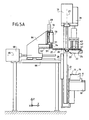
- FIGs 5A to 5G are schematic side views of a first Embodiment according to the invention, which is shown in Figures 3, 4A and 4B Contains components and the successive positions of these components show the steps show a method according to the invention.
- Figure 6 is a schematic side view showing a first Embodiment variant of a device according to the invention shows.
- Figures 7 and 8 are schematic views - each from the front and from the side - a second variant of a device according to the invention;
- Figure 7 is a view according to arrow VII of Figure 8.
- the plug 1 comprises a cylindrical Core with an axis 3 or 2, on the outer surface 4 three deformable Rib rings 5 sit.
- the connector 6 of Figure 1 comprises a body 7, crossed by four Channels 8 to 11, whose respective axes 12 to 15 are parallel to each other.
- the wide channels 8 and 9 open into a first surface 16 of the body 7, while the narrow channels 10 and 11 open into a second surface 17 of the body 7; the Surfaces 16 and 17 are located in the upper part of the connector and are at right angles to the axes 12 to 15 and spaced apart by a distance 18.
- the connector rests on a carrier 19, slidably parallel under the Effect of a cylinder 20 along the generally vertical axis Z (FIGS. 4A to 5G, 7 and 8) along a fixed guide structure 21.
- the surfaces 16 and 17 nestle in particular in FIGS. 1 to 5F of the connector 6 to the lower outer surfaces 22 and 23 of a guide part, respectively 24, firmly attached to the underside 25 of a plug transfer disk 26, which is rotatable is mounted around a vertical axis 27.
- the part 24 serves to guide the plugs 28 to 30 during their transfer from the washer 26 into the channels 8, 10 and 11 of the connector 6.
- it is Part 24 of three cylindrical parallel channels 31 to 33 pierced, their spacing (and the position in a plane XY) is identical to that of channels 8, 10 and 11 and which cross part 24 from side to side and both in its upper Surface 34 open out as well as in one of its lower surfaces 22, 23. So if the part 24, as shown in FIG. 1, resting on the upper surface of the connector 6, are in alignment channels 31 to 33 with channels 8, 10 and 11 and extend them.
- the disc 26 of three cylindrical channels 35 to 37 traverses that open into each of the lower 25 and upper 38 surfaces of the disc 26 and whose position in a plane XY is identical to that of the channels 31 to 33 (and that of channels 8, 10 and 11).
- the diameter (and / or the Transverse dimensions) of channels 31 to 33 and 35 to 37 is chosen to be somewhat smaller than that of the plug intended for the channel in question, such that the plug due to the deformation of its rib rings (reference number 5, Figure 2) there without Difficulties with the help of a pusher can be used and by the Frictional forces are held between these rib rings and the Inside the wall delimiting the channel exist.
- a pusher 39 which in the vertical direction 40 can be moved and that with three fingers parallel to the vertical axis Z 41 to 43 is equipped.
- the configuration (position in a plane XY) of the fingers 41 to 43 corresponds to that of channels 8, 10, 11, 31 to 33 and 35 to 37; the diameter (or transverse dimension) of the fingers 41 to 43 is chosen so that it fits in smoothly the channels of the washer 26 and the part 24 and in the channels of the connector 6 can slide.
- this device for inserting plugs into the Channels of connector 6 is as follows: the three for plugging the three channels 8, 10 and 11 necessary channels are in each case by facilities described below in the channels 35 to 37 of the disc 26 attached.
- the carrier disc is the stopper by rotation about the axis 27 so far that the plugs (reference numerals 35-37, Figure 1) and the channels of the disc that they receive, each with the fingers 41st to 43, which in turn are aligned with channels 31 to 33 of guide 24.
- This the latter guide channels are aligned with channels 8, 10 and 11 of connector 6 - according to their respective axes 12, 14, 15 - by joining the Guide 24 and the connector.
- the guide 24 is fixed to a frame of the Device attached according to the invention, while the connector carrier 19 and that Push member 39, 41, 42, 43 slidable along a vertical axis are attached.
- the connector 6 through its movable support 19 under the guide 24 has been moved and assembled with it, the disc 26 in an orientation as described above, the insertion of the Tamping by a vertical downward movement of the device 39 and the fingers 41 to 43 she wears: the lower end of the fingers presses on the upper end of the Plug and a complementary downward movement of these fingers shifts the Stuff from channels 35 to 37 of the disc into 31 to 33 of the guide and out the latter into the channels 8, 10, 11 of the connector.
- the guide 24 comprises two channels thereof Configuration and the push organ comprises only two fingers 41, 43.
- the transfer disk 26 includes a first pair of openings 35, 37 same structure and function as described above, as well as a second pair Openings 45 and 46, which are diametrically opposed to openings 37 and 35, respectively and have the same shape; consequently they are in a plane XY according to a configuration arranged with that of the openings 35, 37 and that of the channels of the guide and Connector (relatively) is identical.
- the Transfer disk replaced by a substantially rectangular plate 260 which fulfills the same function and rotatable about the axis 27 and parallel to the Z axis is mounted.
- the plate 260 comprises two identical plate elements 261 and 262 which are movably attached to the plate.
- Each element 260, 261 comprises seven Bores 263 that traverse the element and form temporary plug seats that perform the same function as the channels 35 to 37 of the disc 26, Figures 1 and 3.
- the dimensions of each of the bores 263 and their position are each adapted to the dimensions and the position of the channels to be closed specific connector.
- the adaptation of the device to a specific one Connectors are obtained by attaching an insertion guide (reference number 24, Figures 1 and 3) and of two plate elements 261, 262, each of which has channels has a configuration adapted to this particular connector.
- the device for loading the movable plug transfer carrier with Plug includes the following: the two Storage containers 47 and 48 loosely filled plugs are attached to two Linear conveyors 49, 50 supplied, which correspond to two coincident horizontal axes 51, 52 extend parallel to the axis X. An At one end 53, 54 of this supply unit 49, 50, the plugs 1 arranged in rows, as shown in Figure 3.
- This the memory 47, 48 and Conveyor means 49, 50 is preferably similar to those described in the documents US 6,146,058 and EP 1102366 are described.
- a horizontal plate 55 extends through the ends 53, 54 and is pierced of two holes 61, 62, adapted to accommodate one at each end 53, 54 of the conveyor devices 49, 50 delivered plugs.
- the transfer of a stopper from the conveyor to the plate is done by a downward facing Pressure force exerted by a finger 56, 57 on the stopper, which corresponds to the arrows 59 is exerted by an actuator 58, 60 until the plug in the corresponding hole in the plate 55 is inserted.
- the transfer plate is 55 attached to the end of an arm 63 which is fixedly connected to a structure 64.
- the Structure 64 is displaceable parallel to a horizontal axis 65, based on the fixed frame 66 of the device. This shift 67 causes an identical displacement on the plate 55 and the loading members 56 to 58, 60 the plug in the plate.
- the latter are on the axis 69 structure 64 assembled, movable under the action of a translator 70th
- the arm 63 carries the plate 55 to an intermediate height, between which the Ends 53, 54 of the conveyor devices 49, 50 and that of the disk 26.
- the displacement of the structure 64 in the axis 65 enables the plate in to bring a first position, shown in Figure 4A, in which the holes 61, 62 of the Plate the ends 53, 54 of the conveyors 49, 50 face to the Insertion of plugs in the seats of the plate by the pushing members 56, 57 allow up to a second position, shown in Figure 4B, in the at least one of the holes 61, 62 of the plate with a hole 45, 46, 263 in the plate 260 or Disk 26 is aligned to transfer the plugs carried by plate 55 into the To enable the carrier 26, 260 is effected by the fingers 56, 57 of the movable one Insertion unit.
- FIG. 5A shows the components of a device according to the invention in FIG a position before loading the plate 55 with a plug.
- This store is in the figure 5B where the fingers 57 are moved by the actuator 58 which Push the stopper down until it sits in the holes in this plate.
- the actuator 68 which Actuators 58, 70 supporting structure 64 and the plate 55 into the in the Figure 5C position shown where at least one hole of the plate 55 is vertical at least one hole of the disc 26 is aligned.
- the downward movement of the fingers 57 and the actuator 58 (moved by the Actuator 70) inserting the plug or plugs into the Disc as shown in Figure 5D.
- the transfer can be done from stoppers the washer 26 into the connector: this goes from its initial depth Position shown in FIG. 5E in an appendix under the guide 24, shown in Figure 5F. In this position, press through the Actuator 39 moved fingers 41 to 43 the plugs out of the disc the connector passing through the guide.
- At least part of the loading operations (shown in Figures 5A to 5D) of plugs in the carrier 26, 260 by the insertion and transfer unit 55 to 60 can be used simultaneously with the insertion of plugs carried by the carrier 26, 260 into the unused channels of the connector take place (shown in Figures 5E to 5G).
- Another part of the loading operations of the carrier 26, 260 and / or the rotation this support about the axis 27 can be used during the removal of a previously through this device connector provided with plugs while attaching a other connector to be fitted on the carrier, and during the Movements of the connector carrier 19 around it on the underside of the guide 24 to add.
- the position of the Actuators 68 and 71 with respect to that of Figures 3, 5A to 5C vary.
- the axis of parallel displacement of the connector carrier 19 can be horizontal be as in FIG. 6.
- the guide 22 is preferably movable mounted with respect to the Z axis, around the plugs during their transfer into the channels of the connector under the action of the fingers 41 to 43 of the insertion unit 39 accompany.
- the machine includes one electronic control unit 72 connected to a terminal 73 for data entry by the operator of the machine, and a display terminal 74.
- the electronic unit is with those already described above Actuators connected to them under the control of a program according to those in the field of controlling the displacement of machine organs to control conventional rules, especially depending on the by the Operator entered data and the signals integrated in the machine Sensors.
- the operation of the device is the following (in particular related to figure 6):
- An operator places a connector 6 on the carrier 19 and presses the carrier 19 forward.
- a contact detects the presence of the wearer in the escape line guide 24 and initiates the plug insertion operation.
- the pusher moves the Fingers 41 to 43 down which push the plugs out of the disc 26 into the Press guide counterform 24; the counterform 24 and the pusher 39 set theirs Lift movement continues together until the counterform 24 the housing of the connector 6 touched; the pusher pushes the plugs out of the counter mold 24 into the connector 6; the Pusher and the counter form move upwards; the operator pulls on it Carrier 19 back and takes the one provided with the plug of this carrier Connector 6 out.
- the disc cannot move while the handle is moving turn, but attaching the plugs in the washer can be done over a number of Openings are arranged in a straight line with the finger 57 aligned line of the disc, which moves parallel to its guide axis (Reference number 65, Figure 4A).
- the supply and insertion device 47, 49 and 57 up to 60 the plug in the disc moves 65 along this axis Displacement axis (motor 68), combined with the rotation of the disc, enables the fingers 56, 57 of the pusher, a large part of the surface of the disc to reach.
- the disc comprises two diametrically opposite zones holes that are an image of those of the connector.
- the Pushers 56 to 60 push the plugs into them after a programmed configuration Holes.
- the device according to the invention can be equipped with two supply modules be populated (as shown in Figures 4A and 4B) to accommodate the case correspond where two different plugs for the same connector be used.
- connectors are small and require little plug, it is possible to arrange several connectors on a connector carrier 19 and into these connectors use plugs at the same time.
Landscapes
- Engineering & Computer Science (AREA)
- Manufacturing & Machinery (AREA)
- Manufacturing Of Electrical Connectors (AREA)
Abstract
Description
- eine Einheit zur Versorgung mit Stopfen, reihenförmig angeordnet, aus ein Behälter mit lose geschütteten Stopfen,
- eine erste Stopfeneinsetzeinheit, um durch die Versorgungseinheit gelieferte Stopfen in Kanäle eines beweglichen Stopfentransferträgers einzuführen,
- Stopfentransfereinrichtungen, um den beweglichen Stopfentransferträger zu verschieben zwischen einer Stellung zum Laden des beweglichen Transferträgers mit Stopfen und einer Stellung zum Entnehmen der Stopfen,
- eine zweite Stopfeneinsetzeinheit, um Stopfen aus dem beweglichen Stopfentransferträger zu entnehmen und die Stopfen durch die Stopfenführungseinrichtungen hindurch in die Kanäle des Verbinders zu drücken,
- eine elektronische Steuereinheit, um den Betrieb der Stopfenversorgungseinheit, der ersten und zweiten Stopfeneinsetzeinheit sowie der Stopfentransfereinrichtungen zu steuern, insbesondere in Abhängigkeit von Daten eines Datenspeichers, der mit der elektronischen Steuereinheit kooperiert oder in sie integriert ist.
- Entnehmen der Stopfen aus dem Behälter und reihenförmiges Anordnen der Stopfen;
- Transferieren wenigstens eines Stopfens der Stopfenreihe zu einem beweglichen Stopfentransferträger;
- Verschieben des beweglichen Stopfentransferträgers, um wenigstens einen Stopfen in der Flucht wenigstens eines zu verschließenden Kanals des Verbinders anzuordnen;
- Einfügen einer Einsetzführung zwischen dem beweglichen Stopfentransferträger und dem Verbinder;
- Austreiben des genannten, wenigstens einen Stopfens aus dem beweglichen Stopfentransferträger und Einsetzen dieses Stopfens in den Kanal des Verbinders, wobei er durch die Einsetzführungseinrichtung geführt wird.
Claims (11)
- Vorrichtung zum Anbringen eines Stopfens (1, 28 bis 30) in einem Kanal (8 bis 11) eines Verbinders (6), umfassend: einen Stopfenträger (26, 55, 260), fähig wenigstens einen an den genannten Kanal angepassten Stopfen aufzunehmen, Versorgungseinrichtungen (49, 50, 56 bis 60), um den Stopfenträger mit Stopfen zu versorgen, und Transfereinrichtungen (24, 39; 41 bis 43), um wenigstens einen Stopfen des Stopfenträgers zu dem genannten Kanal zu transferieren.
- Vorrichtung zum Einsetzen eines oder mehrerer Stopfen (1, 28 bis 30) in einen oder mehrere Sitze (8 bis 11) eines Verbinders (6), der wenigstens eine Fläche (16, 17) umfasst, in der der Sitz bzw. die Sitze münden, und die genannte Fläche wenigstens eine Form aufweist, wobei diese Einsetzvorrichtung gegebenenfalls die Vorrichtung des Anspruchs 1, Drückeinrichtungen (39, 41 bis 43) zum Hineindrücken des Stopfens oder der Stopfen in den oder die Sitze sowie Führungseinrichtungen umfasst, um den oder die Stopfen während seiner (ihrer) Verschiebung unter der Wirkung der Drückeinrichtungen zu führen, und dabei die Führungseinrichtungen eine Fläche (22, 23) umfassen, deren Form sich an wenigstens einen Teil der Form der Fläche des Verbinders anschmiegt.
- Vorrichtung zum Einsetzen von Stopfen (1, 28 bis 30) in Kanäle (8 bis 11) eines elektrischen Verbinders, die umfasst:eine Einheit (49, 50) zur Versorgung mit Stopfen, reihenförmig angeordnet, aus ein Behälter (47, 48) lose geschütteter Stopfen,eine erste Stopfeneinsetzeinheit (56 bis 60), um durch die Versorgungseinheit gelieferte Stopfen in Kanäle (35 bis 37, 45, 46, 263) eines beweglichen Stopfentransferträgers (26, 260) einzusetzen,eine Betätigungseinrichtung (71), um den beweglichen Stopfentransferträger zu verschieben zwischen einer Stellung zum Laden des beweglichen Transferträgers mit Stopfen und einer Stellung zum Entladen der Stopfen,eine zweite Stopfeneinsetzeinheit (39, 41 bis 43), um Stopfen aus dem beweglichen Stopfentransferträger zu entladen und die Stopfen durch die Stopfenführungseinrichtungen (24) hindurch in die Kanäle des Verbinders zu drücken,eine elektronische Steuereinheit (72), um den Betrieb der Stopfenversorgungseinheit, der ersten und zweiten Stopfeneinsetzeinheit sowie der Stopfentransfereinrichtungen zu steuern, insbesondere in Abhängigkeit von Daten eines Datenspeichers, der mit der elektronischen Steuereinheit kooperiert oder in sie integriert ist.
- Vorrichtung nach einem der Ansprüche 1 bis 3, die einen beweglichen Stopfentransferträger (26, 55, 260) umfasst, der mehrere Kanäle (35 bis 37, 45, 46, 61, 62, 263) enthält, in jedem von denen ein Stopfen durch Reibung mit den Wänden des Kanals festgehalten werden kann.
- Vorrichtung nach Anspruch 4, bei der die Kanäle des beweglichen Stopfentransferträgers sich durch diesen hindurch erstrecken und auf zwei entgegengesetzten Seiten (25, 38) von diesem münden.
- Vorrichtung nach einem der Ansprüche 1 bis 5, die einen beweglichen Stopfentransferträger (26, 55, 260) in Form einer Platte oder Scheibe umfasst, durchbohrt von mehreren Kanälen (35 bis 37, 45, 46, 61, 62, 263), die in einem abnehmbaren Element (261, 262) des beweglichen Stopfentransferträgers vorgesehen sind.
- Vorrichtung nach einem der Ansprüche 1 bis 6, die außerdem umfasst:a) Einrichtungen um über einem Verbinder (6), getragen durch einen beweglichen Träger (19), anzuordnen:ein Stopfenführungsorgan (24),wenigstens einen Teil (261) eines beweglichen Stopfentransferträgers (26, 260), wobei dieser Teil Löcher (263) umfasst,b) Einrichtungen zum Ausrichten der Löcher des Führungsorgans und der Löcher des Teils des beweglichen Trägers (26, 260) mit den zu verschließenden Kanälen des Verbinders,c) Einsetzfinger (41 bis 43), parallelverschiebbar entsprechend den Achsen der Kanäle und Löcher.
- Verfahren zum Einsetzen von Stopfen (1, 28 bis 30) in die Kanäle (8 bis 11) eines Verbinders (6), angeordnet auf einem Verbinderträger (19), wobei die Stopfen in einem Behälter (47, 48) enthalten sind, das die folgenden aufeinanderfolgenden Operationen umfasst:Entnehmen der Stopfen aus dem Behälter und Anordnen zu einer Stopfenreihe;Transferieren wenigstens eines Stopfens der Stopfenreihe zu einem beweglichen Stopfentransferträger (26, 55, 260);Verschieben des beweglichen Stopfentransferträgers, um wenigstens einen Stopfen in der Flucht wenigstens eines zu verschließenden Kanals des Verbinders anzuordnen;Einfügen einer Einsetzführung (24) zwischen dem beweglichen Stopfentransferträger und dem Verbinder;Austreiben des genannten Stopfens aus dem beweglichen Stopfentransferträger und Einsetzen dieses Stopfens in den Kanal des Verbinders, wobei er durch die Einsetzführungseinrichtung geführt wird.
- Verfahren nach Anspruch 8, in dem man simultan das Einsetzen eines ersten Satzes von Stopfen in einen ersten Verbinder und das Laden dieses Trägers mit einem zweiten Satz von Stopfen durchführt, die für einen zweiten Verbinder bestimmt sind.
- Verfahren nach Anspruch 8 oder 9, in dem man Stopfen mit verformbaren Ringrippen (5) mit einem Arbeitstakt von wenigstens 1000 Stopfen pro Stunde einsetzt.
- Dichter elektrischer Verbinder (6), ausgestattet mit wenigstens einem Stopfen (1, 28 bis 30), eingesetzt nach einem Verfahren nach einem der Ansprüche 8 bis 10.
Priority Applications (1)
| Application Number | Priority Date | Filing Date | Title |
|---|---|---|---|
| EP03005570.1A EP1347542B1 (de) | 2002-03-21 | 2003-03-12 | Verfahren und Vorrichtung zum Verschliessen von Kanälen von elektrischen Verbindern |
Applications Claiming Priority (3)
| Application Number | Priority Date | Filing Date | Title |
|---|---|---|---|
| EP02405219 | 2002-03-21 | ||
| EP02405219 | 2002-03-21 | ||
| EP03005570.1A EP1347542B1 (de) | 2002-03-21 | 2003-03-12 | Verfahren und Vorrichtung zum Verschliessen von Kanälen von elektrischen Verbindern |
Publications (2)
| Publication Number | Publication Date |
|---|---|
| EP1347542A1 true EP1347542A1 (de) | 2003-09-24 |
| EP1347542B1 EP1347542B1 (de) | 2015-12-23 |
Family
ID=27790113
Family Applications (1)
| Application Number | Title | Priority Date | Filing Date |
|---|---|---|---|
| EP03005570.1A Expired - Lifetime EP1347542B1 (de) | 2002-03-21 | 2003-03-12 | Verfahren und Vorrichtung zum Verschliessen von Kanälen von elektrischen Verbindern |
Country Status (1)
| Country | Link |
|---|---|
| EP (1) | EP1347542B1 (de) |
Citations (4)
| Publication number | Priority date | Publication date | Assignee | Title |
|---|---|---|---|---|
| US4653182A (en) * | 1984-04-17 | 1987-03-31 | Sumitomo Electric Industries, Ltd. | Apparatus for fitting terminals and rubber stoppers on wires |
| DE9303480U1 (de) * | 1993-03-10 | 1993-04-29 | TSK Testsysteme GmbH & Co, 4952 Porta Westfalica | Vorrichtung zum Eindrücken von Dichtungsstopfen in Freikammern eines Steckers |
| US5551892A (en) * | 1993-10-27 | 1996-09-03 | Yazaki Corporation | Water-proof connector and dummy plug for water-proof connector |
| EP1102366A1 (de) | 1999-11-18 | 2001-05-23 | komax Holding AG | Abdichtungsstation für Kabelbaum herstellende Maschine |
Family Cites Families (1)
| Publication number | Priority date | Publication date | Assignee | Title |
|---|---|---|---|---|
| US5266045A (en) * | 1991-10-28 | 1993-11-30 | Yazaki Corporation | Waterproof connector |
-
2003
- 2003-03-12 EP EP03005570.1A patent/EP1347542B1/de not_active Expired - Lifetime
Patent Citations (4)
| Publication number | Priority date | Publication date | Assignee | Title |
|---|---|---|---|---|
| US4653182A (en) * | 1984-04-17 | 1987-03-31 | Sumitomo Electric Industries, Ltd. | Apparatus for fitting terminals and rubber stoppers on wires |
| DE9303480U1 (de) * | 1993-03-10 | 1993-04-29 | TSK Testsysteme GmbH & Co, 4952 Porta Westfalica | Vorrichtung zum Eindrücken von Dichtungsstopfen in Freikammern eines Steckers |
| US5551892A (en) * | 1993-10-27 | 1996-09-03 | Yazaki Corporation | Water-proof connector and dummy plug for water-proof connector |
| EP1102366A1 (de) | 1999-11-18 | 2001-05-23 | komax Holding AG | Abdichtungsstation für Kabelbaum herstellende Maschine |
Also Published As
| Publication number | Publication date |
|---|---|
| EP1347542B1 (de) | 2015-12-23 |
Similar Documents
| Publication | Publication Date | Title |
|---|---|---|
| DE2744235A1 (de) | Maschine zum aufeinanderfolgenden einsetzen von bauelementen mit mehrfachanschluessen | |
| DE3540201A1 (de) | Vorrichtung zum automatischen montieren von zugfedern | |
| WO1998047007A1 (de) | Magazin zur bevorratung von testelementen | |
| EP0272395B1 (de) | Transportvorrichtung für elektrische Kabel | |
| DE2630543A1 (de) | Verfahren und vorrichtung zum uebertragen gleicher kleiner fluessigkeitsmengen von einer vielzahl von behaeltern in proben | |
| DE60004404T2 (de) | Vorrichtung zum handhaben von vorformlingen mit einem horizontalachsigen drehturm | |
| EP0144715A1 (de) | Vorrichtung zum Weiterleiten von Bauteilen, insbesondere von integrierten Chips, von einem Eingangsmagazin zu einnem Ausgangsmagazin | |
| DE3340182A1 (de) | Vorrichtung zum weiterleiten von bauteilen, insbesondere von integrierten chips, von einem eingangsmagazin zu einem ausgangsmagazin | |
| DE1486033A1 (de) | Fuelleinrichtung | |
| DE2844169C2 (de) | Vorrichtung zum Bestücken gedruckter Schaltungen | |
| DE3221620A1 (de) | Vorrichtung zum anbringen von komponenten | |
| DE4400948C2 (de) | Vorrichtung zum Drücken von Chip-Komponenten in eine Halteplatte | |
| DE2735852C2 (de) | Vorrichtung zum automatischen Entfernen und Wiedereinsetzen einer Lochmaskenanordnung einer Farbfernsehröhre | |
| DE2804501A1 (de) | Filmtraeger fuer die zahnaerztliche roentgentechnik | |
| DE3223086A1 (de) | Vorrichtung zur herstellung elektrischer kabelbaeume | |
| EP1347542B1 (de) | Verfahren und Vorrichtung zum Verschliessen von Kanälen von elektrischen Verbindern | |
| DE102015112468A1 (de) | Vorrichtung und Verfahren zum Positionieren und Übergeben von Gegenständen | |
| DE602004002624T2 (de) | Umlaufförderer | |
| DE4137982A1 (de) | Verfahren zum einlegen von etiketten in die tiefziehform einer thermoformmaschine oder verpackungsmaschine und vorrichtung zur durchfuehrung des verfahrens | |
| DE2914210A1 (de) | Vorrichtung zum einsetzen elektrischer kontakte | |
| EP1775219A2 (de) | Vorrichtung zum geordneten Zuführen und Ablegen zu verpackender Kleinteile in die Näpfe einer Folienbahn | |
| EP1653577B1 (de) | Kabelspeichervorrichtung und Verfahren zum Handhaben von Kabelenden | |
| DE102022114115A1 (de) | Tablettenträger zum Zwischentransport von Tabletten in einem Verblisterungsprozess, Befüllvorrichtung für einen Tablettenträger und Verfahren zum Befüllen eines Tablettenträgers | |
| DE102005047268B4 (de) | Vorrichtung zum Übergeben von Spritzen, Ampullen oder dergl. | |
| DE202021104040U1 (de) | Wiegevorrichtung für eine Kapsel und Kapselfüllmaschine mit Wiegevorrichtung |
Legal Events
| Date | Code | Title | Description |
|---|---|---|---|
| PUAI | Public reference made under article 153(3) epc to a published international application that has entered the european phase |
Free format text: ORIGINAL CODE: 0009012 |
|
| AK | Designated contracting states |
Kind code of ref document: A1 Designated state(s): AT BE BG CH CY CZ DE DK EE ES FI FR GB GR HU IE IT LI LU MC NL PT RO SE SI SK TR |
|
| AX | Request for extension of the european patent |
Extension state: AL LT LV MK |
|
| 17P | Request for examination filed |
Effective date: 20040306 |
|
| AKX | Designation fees paid |
Designated state(s): CH DE FR GB IT LI |
|
| 17Q | First examination report despatched |
Effective date: 20120329 |
|
| REG | Reference to a national code |
Ref country code: DE Ref legal event code: R079 Ref document number: 50315386 Country of ref document: DE Free format text: PREVIOUS MAIN CLASS: H01R0043000000 Ipc: H01R0013520000 |
|
| GRAP | Despatch of communication of intention to grant a patent |
Free format text: ORIGINAL CODE: EPIDOSNIGR1 |
|
| RIC1 | Information provided on ipc code assigned before grant |
Ipc: H01R 43/00 20060101ALI20150722BHEP Ipc: H01R 13/52 20060101AFI20150722BHEP |
|
| INTG | Intention to grant announced |
Effective date: 20150807 |
|
| RIN1 | Information on inventor provided before grant (corrected) |
Inventor name: SORIANO, LOUIS |
|
| GRAS | Grant fee paid |
Free format text: ORIGINAL CODE: EPIDOSNIGR3 |
|
| GRAA | (expected) grant |
Free format text: ORIGINAL CODE: 0009210 |
|
| AK | Designated contracting states |
Kind code of ref document: B1 Designated state(s): CH DE FR GB IT LI |
|
| REG | Reference to a national code |
Ref country code: GB Ref legal event code: FG4D Free format text: NOT ENGLISH |
|
| REG | Reference to a national code |
Ref country code: CH Ref legal event code: EP |
|
| REG | Reference to a national code |
Ref country code: DE Ref legal event code: R096 Ref document number: 50315386 Country of ref document: DE |
|
| REG | Reference to a national code |
Ref country code: CH Ref legal event code: NV Representative=s name: INVENTIO AG, CH |
|
| REG | Reference to a national code |
Ref country code: DE Ref legal event code: R097 Ref document number: 50315386 Country of ref document: DE |
|
| PLBE | No opposition filed within time limit |
Free format text: ORIGINAL CODE: 0009261 |
|
| STAA | Information on the status of an ep patent application or granted ep patent |
Free format text: STATUS: NO OPPOSITION FILED WITHIN TIME LIMIT |
|
| GBPC | Gb: european patent ceased through non-payment of renewal fee |
Effective date: 20160323 |
|
| 26N | No opposition filed |
Effective date: 20160926 |
|
| REG | Reference to a national code |
Ref country code: FR Ref legal event code: ST Effective date: 20161130 |
|
| PG25 | Lapsed in a contracting state [announced via postgrant information from national office to epo] |
Ref country code: FR Free format text: LAPSE BECAUSE OF NON-PAYMENT OF DUE FEES Effective date: 20160331 Ref country code: GB Free format text: LAPSE BECAUSE OF NON-PAYMENT OF DUE FEES Effective date: 20160323 |
|
| PGFP | Annual fee paid to national office [announced via postgrant information from national office to epo] |
Ref country code: DE Payment date: 20200320 Year of fee payment: 18 |
|
| PGFP | Annual fee paid to national office [announced via postgrant information from national office to epo] |
Ref country code: IT Payment date: 20200318 Year of fee payment: 18 |
|
| REG | Reference to a national code |
Ref country code: DE Ref legal event code: R119 Ref document number: 50315386 Country of ref document: DE |
|
| PG25 | Lapsed in a contracting state [announced via postgrant information from national office to epo] |
Ref country code: DE Free format text: LAPSE BECAUSE OF NON-PAYMENT OF DUE FEES Effective date: 20211001 |
|
| PG25 | Lapsed in a contracting state [announced via postgrant information from national office to epo] |
Ref country code: IT Free format text: LAPSE BECAUSE OF NON-PAYMENT OF DUE FEES Effective date: 20210312 |
|
| PGFP | Annual fee paid to national office [announced via postgrant information from national office to epo] |
Ref country code: CH Payment date: 20220324 Year of fee payment: 20 |
|
| REG | Reference to a national code |
Ref country code: CH Ref legal event code: PL |