EP1347250A2 - Kollektormodul - Google Patents
Kollektormodul Download PDFInfo
- Publication number
- EP1347250A2 EP1347250A2 EP03002437A EP03002437A EP1347250A2 EP 1347250 A2 EP1347250 A2 EP 1347250A2 EP 03002437 A EP03002437 A EP 03002437A EP 03002437 A EP03002437 A EP 03002437A EP 1347250 A2 EP1347250 A2 EP 1347250A2
- Authority
- EP
- European Patent Office
- Prior art keywords
- tube
- collector module
- collector
- module according
- locking elements
- Prior art date
- Legal status (The legal status is an assumption and is not a legal conclusion. Google has not performed a legal analysis and makes no representation as to the accuracy of the status listed.)
- Granted
Links
Images





Classifications
-
- F—MECHANICAL ENGINEERING; LIGHTING; HEATING; WEAPONS; BLASTING
- F24—HEATING; RANGES; VENTILATING
- F24S—SOLAR HEAT COLLECTORS; SOLAR HEAT SYSTEMS
- F24S10/00—Solar heat collectors using working fluids
- F24S10/40—Solar heat collectors using working fluids in absorbing elements surrounded by transparent enclosures, e.g. evacuated solar collectors
- F24S10/45—Solar heat collectors using working fluids in absorbing elements surrounded by transparent enclosures, e.g. evacuated solar collectors the enclosure being cylindrical
-
- F—MECHANICAL ENGINEERING; LIGHTING; HEATING; WEAPONS; BLASTING
- F24—HEATING; RANGES; VENTILATING
- F24S—SOLAR HEAT COLLECTORS; SOLAR HEAT SYSTEMS
- F24S25/00—Arrangement of stationary mountings or supports for solar heat collector modules
- F24S25/30—Arrangement of stationary mountings or supports for solar heat collector modules using elongate rigid mounting elements extending substantially along the supporting surface, e.g. for covering buildings with solar heat collectors
-
- F—MECHANICAL ENGINEERING; LIGHTING; HEATING; WEAPONS; BLASTING
- F24—HEATING; RANGES; VENTILATING
- F24S—SOLAR HEAT COLLECTORS; SOLAR HEAT SYSTEMS
- F24S80/00—Details, accessories or component parts of solar heat collectors not provided for in groups F24S10/00-F24S70/00
- F24S80/30—Arrangements for connecting the fluid circuits of solar collectors with each other or with other components, e.g. pipe connections; Fluid distributing means, e.g. headers
-
- Y—GENERAL TAGGING OF NEW TECHNOLOGICAL DEVELOPMENTS; GENERAL TAGGING OF CROSS-SECTIONAL TECHNOLOGIES SPANNING OVER SEVERAL SECTIONS OF THE IPC; TECHNICAL SUBJECTS COVERED BY FORMER USPC CROSS-REFERENCE ART COLLECTIONS [XRACs] AND DIGESTS
- Y02—TECHNOLOGIES OR APPLICATIONS FOR MITIGATION OR ADAPTATION AGAINST CLIMATE CHANGE
- Y02E—REDUCTION OF GREENHOUSE GAS [GHG] EMISSIONS, RELATED TO ENERGY GENERATION, TRANSMISSION OR DISTRIBUTION
- Y02E10/00—Energy generation through renewable energy sources
- Y02E10/40—Solar thermal energy, e.g. solar towers
- Y02E10/44—Heat exchange systems
-
- Y—GENERAL TAGGING OF NEW TECHNOLOGICAL DEVELOPMENTS; GENERAL TAGGING OF CROSS-SECTIONAL TECHNOLOGIES SPANNING OVER SEVERAL SECTIONS OF THE IPC; TECHNICAL SUBJECTS COVERED BY FORMER USPC CROSS-REFERENCE ART COLLECTIONS [XRACs] AND DIGESTS
- Y02—TECHNOLOGIES OR APPLICATIONS FOR MITIGATION OR ADAPTATION AGAINST CLIMATE CHANGE
- Y02E—REDUCTION OF GREENHOUSE GAS [GHG] EMISSIONS, RELATED TO ENERGY GENERATION, TRANSMISSION OR DISTRIBUTION
- Y02E10/00—Energy generation through renewable energy sources
- Y02E10/40—Solar thermal energy, e.g. solar towers
- Y02E10/47—Mountings or tracking
Definitions
- the invention relates to a collector module with a two chambers having collecting device, in particular manifold, the at least has a nipple arranged perpendicular to the collecting device, with at least one collector tube, which is a cladding tube and an absorber tube has, wherein the absorber tube is attached to the nipple and in the nipple a coaxial tube is arranged, on the one hand in the absorber tube and on the other hand is fixed in the collecting device, and with one the collecting device encompassing and receiving the open end of the cladding tube Connecting element.
- Such a collector module is from utility model G 201 01 139 known.
- the collector tube with its absorber tube is on the nipple attached.
- the connecting element is designed such that the Collector tube can be inserted. All components are over Plug connections connected to each other. This is to ensure that there is a certain degree of mobility in the case of thermal expansions. Different variants are described, which include, among others a non-positive and a positive recording of the collector tube in the Obtain connector.
- each collector tube Connection element is provided, which is a cup-shaped receiving element has, in which the cladding tube is glued that cup-shaped Receiving element is formed on a U-shaped fastener, which Grips around, and that on the fastener Closure device is arranged.
- the closure device is designed in this way and on the fastening element arranged that the collecting device, in particular the collecting tube, between the fastener and the fastener either is held clamped or displaceable, one in both cases Torsionally rigid connection is established with the collection device.
- a Clamping or sliding attachment is based on the internal dimensions of fastener and closure device with respect to the External dimensions of the collection device set.
- the closure device can be of this type be designed so that it can be opened and closed so that a Exchange of individual pipes is possible.
- Gluing the collector tube into the cup-shaped receiving element prevents the hydraulic pressure from pulling the collector tube off the nipple.
- the sealing of the absorber tube, the on the nipple by means of one or two O-rings not by external forces burdens, which increases operational safety and longevity.
- an outside Forces are all those forces that are not parallel to the nipple axis are directed, e.g. Snow loads, improper installation, etc.
- the collector tube is preferably cup-shaped in this way Glued receiving element that the entire annular gap between Collector tube and the wall surrounding the collector tube over the entire scope is filled. It advantageously becomes an adhesive used, which shrinks only slightly during curing to crack or To avoid detachments. In particular, an comes or Two-component silicone-based adhesive is suitable for this.
- the collector tube is glued into the cup-shaped receiving element this glue in conjunction with the O-ring seal on the nipple nevertheless for sufficient elasticity of the connection, so that the Risk of breakage during assembly and operation is reduced.
- Another advantage of gluing the collector tube in the form of a cup Receiving element is that in the event of a break in the inner tube (Coaxial tube) in the absorber tube, the heat transfer fluid in any case, that is even if the nipple breaks, it first flows into the cavity that the Cladding tube forms. An exit of the heat transfer medium from the system is thus effectively prevented.
- the adhesive ensures that the necessary holding force is evenly distributed over the circumference of the collector tube. Irregularities due to small production-related pipe bends are compensated.
- the connecting element does not come into contact with the heat transfer medium and is thus not exposed to chemical attacks. This allows the use mostly also cheaper plastic materials are temperature-resistant, but are susceptible to contact with heat transfer fluids, such as. glass fiber reinforced polyamide.
- the closure device is a in the longitudinal direction of the Collecting tube movable slide.
- the closure device is a in the longitudinal direction of the Collecting tube movable slide.
- the free end two legs of the U-shaped fastening element locking elements arranged, which cooperate with locking elements of the slide.
- These locking elements can be tongue and groove, for example exist, which are preferably in the longitudinal direction of the collecting device extend.
- closure device on Fastener is articulated pivot element.
- This swivel element is preferably opened by one in the longitudinal direction when opening Collecting device pivoted pivoted so that a Exchange of the collector tube together with the connecting element is possible.
- the provision of a swivel or folding element has the Advantage that the closure device remains on the fastener and thus cannot be lost during an exchange.
- This swivel element is preferably on one leg of the U-shaped fastening element articulated by means of a hinge and snaps into a corresponding element on the opposite leg of the U-shaped fastening element.
- This pivot element is also designed such that in the locked Condition the collecting device is held clamped or displaceable.
- width of the U-shaped fastening element is smaller than that Outside diameter of the cup-shaped receiving element.
- the width is allowed however, not so small that no torsionally stiff connection is guaranteed.
- the width B of the fastener is in Range from D / 3 to D, where D is the diameter of the cup-shaped Designated receiving element.
- the cup-shaped receiving elements preferably have on the outside their side walls opposite in the direction of the collecting device Locking elements on that with locking elements of an adjacent cup-shaped receiving element cooperate.
- the collector tubes are pushed together with their connecting elements so far that Adjacent side walls of the cup-shaped receiving elements against one another.
- the mutual interlocking Torsional rigidity increased significantly.
- shutter and Fastener preferably formed such that the Collection device is held displaceably.
- these locking elements also allow trouble-free operation Release, especially if these locking elements, for example consist of tongue and groove that extend in the longitudinal direction of the collector tubes extend.
- the Closure device opened and the collector tube with the Connecting element moved in the longitudinal direction of the collector tube, wherein the locking elements of the cup-shaped receiving element from the Locking elements of the adjacent cup-shaped receiving elements slip out.
- a new collector tube with the appropriate connection element can be installed.
- Roof fastening element arranged, which preferably consists of at least one Ring element with perpendicular to the longitudinal axis of the connecting element arranged hole opening exists. Through this hole opening is a bolt or the like stuck and fastened, which in turn has a suitable Holding device connects to the roof.
- a foot cap glued onto the collector tube is similar like the cup-shaped receiving elements on the outside of it opposite side walls locking elements that with Interacting locking elements of adjacent foot caps.
- These locking elements are preferably also Grooves and tongues, preferably in the longitudinal direction of the collector tube are arranged so that when replacing a collector tube with a single movement the locks of the cup-shaped receiving elements and the locks on the foot caps are released.
- the foot cap preferably has a base with holding elements, with which the foot caps in a corresponding attachment on the roof intervention. These holding elements preferably engage in a corresponding one Rail that is attached to the roof.
- the arrangement is preferred chosen so that length extensions also by moving the Base to be compensated.
- the foot cap still has a drain opening, so Rainwater without problems when the collector modules are arranged at an angle can expire.
- a collector module 1 is shown with collector tubes 2, the at their head ends each interconnected connecting elements 40 and also individually connected at their foot end Have foot caps 80.
- the Connecting elements 40 have a cup-shaped receiving element 41, in that the collector tube 2 is glued.
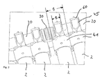
- FIG. 1 A schematic diagram of the Collector module 1 shown, so that the connecting elements 40, the are described in more detail below, can be seen more clearly.
- the Connecting elements 40 have a cup-shaped receiving element 41, in that the collector tube 2 is glued.
- the width B of the U-shaped fastening element 45 is significantly smaller than the outer diameter D of the cup-shaped receiving element 41, so that between two adjacent fasteners 45 a space remains so that the collector connection 30 can be arranged there and this does not lead to a significant increase in the pipe spacing along the Collection device 20 leads.
- Fig. 3 is a section through a collector tube 2 with attached Connection element 40, manifold 20 and foot cap 80 shown.
- the Collector tube 2 consists of a cladding tube 3, which has a connecting wall 5 is fused to the inner absorber tube 4. This structure of the Collector tube 2 is known from the prior art.
- the inside of the Absorber tube 4 is thus accessible at the opening 6, so that there is a Coaxial tube 7 and a nipple 24 can be inserted.
- the manifold 20 consists essentially of an outer wall 21 and a coaxially arranged inner tube 22, so that two chambers for the Inlet and outlet of the heat transfer medium are formed.
- a plurality of nipples 24 are arranged, which are in radial Extend direction from manifold 20. 3 is one of these nipples 24 shown, which extends into the absorber tube 4, where a Sealing with two O-rings located on the outside of the nipple 25 takes place.
- the coaxial tube 7 is used in the interior of the nipple on the one hand abuts an opening of the inner wall 22 and on the other End supported on a spring 8 arranged in the absorber tube 4.
- the connecting element 40 has a cup-shaped receiving element 41, in that the cladding tube 3 is glued in by means of an adhesive layer 9.
- the adhesive layer 9 does not extend over the entire inner surface of the cup-shaped receiving element 41, because that Cladding tube 3 has a circumferential bead 10 and an adhesive layer in this area is sufficient to securely fix the collector tube 2 guarantee.
- an opening 43 is provided for receiving the nipple 24.
- the fastener 45 is integrally formed, which is essentially two legs 46a, b, which encompass the manifold 20 in the shape of a jaw.
- locking elements 47a, b are designed as springs and with corresponding Locking elements 62a, b on the legs 61a, b of the closure element 60 interact.
- These locking elements 62a, b are accordingly designed as grooves. Grooves and tongues extend in Longitudinal direction of the manifold 20.
- a handle 63 is arranged with which as Slider formed closure member 60 in the longitudinal direction of the header 20 can be moved to release the lock, so that Collector tube 2 together with the connecting element 40 from the nipple 24 and the manifold 20 can be removed.
- the foot cap 80 At the opposite end of the collector tube 2 is the foot cap 80 arranged, which in principle is a similar cup-shaped receiving element includes.
- the collector tube 2 or the cladding tube 3 is the Collector tube 2 glued over the adhesive layer 81.
- the foot cap 80 has at the lower end a base 82 with holding element 88, which for Fastening on the roof is used.
- In the lower part of the curvature of the Foot cap 80 is provided with an outlet opening 87 so that it can possibly rainwater collecting between the collector tube 2 and the foot cap 80 can run unhindered, which is particularly advantageous if one inclined arrangement is made on a sloping roof.
- FIG. 4 is a perspective view of a connecting element 40 shown.
- the cup-shaped receiving element 41 has on the in Longitudinal direction of the manifold 20 arranged opposite Side walls 48 and 49 locking elements in the form of grooves and Springs 50a, b.
- the two side walls 48, 49 are plane-parallel.
- adjacent walls 48, 49 are two juxtaposed cup-shaped receiving elements 41 immediately to each other, so that the springs of one wall into the grooves of the engage opposite wall and thus the connecting elements 40 lock together and thus form a stable arrangement.
- Roof fastening element 70 in the form of a ring element with a Hole opening 71 arranged (see. Fig. 4).
- the hole opening 71 extends perpendicular to the longitudinal direction of the manifold 20, so that there is a bolt or Similar can be inserted and thus a roof attachment is made possible.
- On the opposite side can be another Roof fastening element 70 may be arranged, but it is usually sufficient one of these roof fastening elements 70 per connecting element 40.
- Locking elements 47a, b arranged in the shown here Embodiment consist of springs.
- the associated closure element 60 is also curved and has two legs 61a, b, on their Outside two grooves 62a, b are arranged as locking elements in the corresponding locking elements 47a, b of the U-shaped Fastening element 45 engage.
- a slide is thus formed which in the longitudinal direction of the manifold 20 can be moved to the Attachment of the connecting element 40 to be detached from the collecting tube 20.
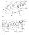
- FIG. 7 is a top view of the arrangement shown in FIG. 6 shown.
- a collector tube 2 together with the Roof fastening device shown.
- This plate 73 lies on the rail 74, with the short leg on the outside of the Rail 74 abuts and forms a stop.
- a U-shaped curved rail 75 is provided, in which the foot cap 80 with its base 88 is plugged in.
- the rail 75 is in turn fastened to a rail 74. at this type of roof mounting, the collector tube 2 between the Rails kept taut.
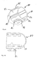
- FIG. 9 is a bottom perspective view of a foot cap 80 shown.
- the foot cap has two opposite plane-parallel ones Outer walls 83 and 84 on which locking elements 86 and 85 are in shape of grooves and tongues are arranged so that a corresponding arrangement as is realized with a cup-shaped receiving element 41 and a Connection with adjacent foot caps 80 is possible.
- a base 82 is formed, which is connected to the plate via a plate-shaped holding element 88 U-shaped rail 75 can be connected.
- the outlet opening 87 is shown, which is already in connection with the Fig. 3 has been explained and is shown in Fig. 10.
- connection 30 of two manifolds 20 is shown, the can be inserted into one another, the seal via two O-rings 31a he follows.
- FIG. 12 shows a further embodiment of a connecting element 40, which is different from the embodiment shown in FIG. 4 differs in that the closure element 60 on a hinge 64 on free end of the leg 46b is pivoted.
- a locking element 47a is arranged, which when the Closure element 60 with a corresponding locking element 61a locked and thus occupies the closed position shown in Fig. 12b.
Landscapes
- Engineering & Computer Science (AREA)
- Mechanical Engineering (AREA)
- Physics & Mathematics (AREA)
- Sustainable Development (AREA)
- Sustainable Energy (AREA)
- Thermal Sciences (AREA)
- Chemical & Material Sciences (AREA)
- Life Sciences & Earth Sciences (AREA)
- General Engineering & Computer Science (AREA)
- Combustion & Propulsion (AREA)
- Quick-Acting Or Multi-Walled Pipe Joints (AREA)
- Roof Covering Using Slabs Or Stiff Sheets (AREA)
- Branch Pipes, Bends, And The Like (AREA)
- External Artificial Organs (AREA)
- Casings For Electric Apparatus (AREA)
- Microwave Tubes (AREA)
Abstract
Description
- Fig. 1
- ein Kollektormodul mit Kollektorrohren, Verbindungselementen und Fußkappen,
- Fig. 2
- eine Ausschnittvergrößerung des Kollektormoduls im Bereich der Verbindungselemente,
- Fig. 3
- einen Längsschnitt durch ein Kollektorrohr mit Verbindungselement und Fußkappe,
- Fig. 4
- eine perspektivische Ansicht eines Verbindungselementes mit Verschlußeinrichtung,
- Fig. 5
- einen Schnitt durch das in Fig. 4 gezeigte Verbindungselement,
- Fig. 6
- eine Unteransicht eines Abschnittes des Kollektormoduls mit der Dachbefestigungseinrichtung,
- Fig. 7
- eine Draufsicht auf die in Fig. 6 gezeigte Dachbefestigungseinrichtung,
- Fig. 8
- eine Seitenansicht des Kollektormoduls mit den entsprechenden Dachbefestigungseinrichtungen,
- Fig. 9
- eine perspektivische Ansicht einer Fußkappe,
- Fig. 10
- einen Schnitt längs der Linie X-X der in Fig. 9 gezeigten Fußkappe,
- Fig. 11
- die Verbindung zweier Kollektormodule im Schnitt,
- Fig. 12a+b
- einen Schnitt durch ein Verbindungselement mit einer Verschlußeinrichtung gemäß einer weiteren Ausführungsform im geöffneten und im geschlossenen Zustand.
- 1
- Kollektormodul
- 2
- Kollektorrohr
- 3
- Hüllrohr
- 4
- Absorberrohr
- 5
- Verbindungswand
- 6
- Öffnung
- 7
- Koaxialrohr
- 8
- Feder
- 9
- Klebstoffschicht
- 10
- Sicke
- 20
- Sammelrohr
- 21a,b
- Außenwand
- 22
- Innenrohr
- 24
- Nippel
- 25
- O-Ring
- 26
- Pfeilrichtung
- 27
- Pfeilrichtung
- 30
- Sammlerverbindung
- 31
- O-Ring
- 40
- Verbindungselement
- 41
- tassenförmiges Aufnahmeelement
- 42
- Bodenwand
- 43
- Öffnung
- 45
- U-förmiges Befestigungselement
- 46a,b
- Schenkel
- 47a, b
- Verriegelungselement
- 48
- Seitenwand
- 49
- Seitenwand
- 50a
- Nut
- 50b
- Feder
- 60
- Verschlußeinrichtung
- 61a,b
- Schenkel
- 62a,b
- Verriegelungselement
- 63
- Griffstück
- 70
- Dachbefestigungselement
- 71
- Lochöffnung
- 72
- Bolzen
- 73
- L-Profilplatte
- 74
- Schiene
- 75
- Schiene
- 80
- Fußkappe
- 81
- Klebstoffschicht
- 82
- Sockel
- 83
- Seitenwand
- 84
- Seitenwand
- 85
- Verriegelungselement
- 86
- Verriegelungselement
- 87
- Ablauföffnung
- 88
- Halteelement
Claims (15)
- Kollektormodul mit einer zwei Kammern aufweisenden Sammeleinrichtung, insbesondere Sammelrohr, die mindestens einen senkrecht zur Sammeleinrichtung angeordneten Nippel aufweist, mit mindestens einem Kollektorrohr, das ein Hüllrohr und ein Absorberrohr aufweist, wobei das Absorberrohr auf dem Nippel aufgesteckt ist und im Nippel ein Koaxialrohr angeordnet ist, das einerseits im Absorberrohr und andererseits im Sammelrohr fixiert ist, und mit einem die Sammeleinrichtung umgreifenden und das Ende des Hüllrohrs aufnehmenden Verbindungselement, dadurch gekennzeichnet, daß für jedes Kollektorrohr ein eigenes Verbindungselement vorgesehen ist, das ein tassenförmiges Aufnahmeelement (41) aufweist, in das das Hüllrohr (2) eingeklebt ist,
daß am tassenförmigen Aufnahmeelement (41) ein U-förmiges Befestigungselement (45) angeformt ist, das die Sammeleinrichtung (20) umgreift, und
daß am Befestigungselement (45) eine Verschlußeinrichtung (60) angeordnet ist. - Kollektormodul nach Anspruch 1, dadurch gekennzeichnet, daß die Verschlußeinrichtung (60) ein in Längsrichtung des Sammelrohres (20) beweglicher Schieber ist.
- Kollektormodul nach Anspruch 1 oder 2, dadurch gekennzeichnet, daß am freien Ende der beiden Schenkel (46a,b) des U-förmigen Befestigungselementes (45) Verriegelungselemente (47a,b) angeordnet sind, die mit Verriegelungselementen (62a,b) des Schiebers (60) zusammenwirken.
- Kollektormodul nach einem der Ansprüche 1 bis 3, dadurch gekennzeichnet, daß die Verriegelungselemente (47a,b,62a,b) aus Nut und Feder bestehen.
- Kollektormodul nach einem der Ansprüche 1 bis 4, dadurch gekennzeichnet, daß sich die Nuten und Federn (47a,b,62a,b) in Längsrichtung des Sammelrohres (20) erstrecken.
- Kollektormodul nach Anspruch 1, dadurch gekennzeichnet, daß die Verschlußeinrichtung (60) ein am Befestigungselement angelenktes Schwenkelement ist.
- Kollektormodul nach einem der Ansprüche 1 bis 6, dadurch gekennzeichnet, daß die sich in Längsrichtung des Sammelrohrs (20) erstreckende Breite B des U-förmigen Befestigungselementes (45) kleiner als der Außendurchmesser D des tassenförmigen Aufnahmeelementes (41) ist.
- Kollektormodul nach einem der Ansprüche 1 bis 7, dadurch gekennzeichnet, daß das tassenförmige Aufnahmeelement (41) an der Außenseite seiner in Richtung des Sammelrohrs (20) gegenüberliegenden Seitenwänden (48,49) Verriegelungselemente (50a,b) aufweist, die mit Verriegelungselementen (50a,b) eines benachbarten tassenförmigen Aufnahmeelementes (41) zusammenwirken.
- Kollektormodul nach einem der Ansprüche 1 bis 8, dadurch gekennzeichnet, daß am Verbindungselement (40) im Übergangsbereich vom tassenförmigen Aufnahmeelement (41) und U-förmigen Befestigungselement (45) ein Dachbefestigungselement (70) angeordnet ist.
- Kollektormodul nach Anspruch 9, dadurch gekennzeichnet, daß das Dachbefestigungselement (70) mindestens ein Ringelement mit senkrecht zur Längsachse des Verbindungselementes (40) angeordneter Lochöffnung (71) ist.
- Kollektormodul nach einem der Ansprüche 1 bis 9, dadurch gekennzeichnet, daß am geschlossenen Ende des Kollektorrohres (2) eine Fußkappe (80) aufgeklebt ist.
- Kollektormodul nach Anspruch 9, dadurch gekennzeichnet, daß die Fußkappe (80) eine Ablauföffnung (87) aufweist.
- Kollektormodul nach einem der Ansprüche 1 bis 12, dadurch gekennzeichnet, daß die Fußkappe (80) an der Außenseite ihrer gegenüberliegenden Seitenwände (83,84) Verriegelungselemente (85,86) aufweist, die mit Verriegelungselementen (85,86) benachbarter Fußkappen (80) zusammenwirken.
- Kollektormodul nach einem der Ansprüche 1 bis 13, dadurch gekennzeichnet, daß die Verriegelungselemente (85,86) aus Nuten und Federn bestehen.
- Kollektormodul nach einem der Ansprüche 1 bis 14, dadurch gekennzeichnet, daß die Fußkappe (80) einen Sockel (82) mit mindestens einem Halteelement (88) aufweist.
Applications Claiming Priority (2)
| Application Number | Priority Date | Filing Date | Title |
|---|---|---|---|
| DE10212977A DE10212977C1 (de) | 2002-03-19 | 2002-03-19 | Kollektormodul |
| DE10212977 | 2002-03-19 |
Publications (3)
| Publication Number | Publication Date |
|---|---|
| EP1347250A2 true EP1347250A2 (de) | 2003-09-24 |
| EP1347250A3 EP1347250A3 (de) | 2005-03-30 |
| EP1347250B1 EP1347250B1 (de) | 2006-04-19 |
Family
ID=27771506
Family Applications (1)
| Application Number | Title | Priority Date | Filing Date |
|---|---|---|---|
| EP03002437A Expired - Lifetime EP1347250B1 (de) | 2002-03-19 | 2003-02-05 | Kollektormodul |
Country Status (9)
| Country | Link |
|---|---|
| US (1) | US7107984B2 (de) |
| EP (1) | EP1347250B1 (de) |
| KR (1) | KR100927123B1 (de) |
| CN (1) | CN1297788C (de) |
| AT (1) | ATE323875T1 (de) |
| CA (1) | CA2419800A1 (de) |
| DE (2) | DE10212977C1 (de) |
| ES (1) | ES2262908T3 (de) |
| IL (1) | IL154487A (de) |
Families Citing this family (4)
| Publication number | Priority date | Publication date | Assignee | Title |
|---|---|---|---|---|
| GB0710237D0 (en) * | 2007-05-30 | 2007-07-11 | Thermomax Ltd | Solar collector assembley |
| IE20100513A1 (en) * | 2009-08-21 | 2011-03-30 | Kingspan Holdings Irl Ltd | A solar collector |
| DE102011118871B3 (de) * | 2011-11-18 | 2013-01-31 | Ritter Energie- Und Umwelttechnik Gmbh & Co. Kg | Solarkollektor |
| US20200355404A1 (en) * | 2017-11-10 | 2020-11-12 | Aspire Polymers Pty Ltd | Improvements relating to solar water heaters |
Citations (1)
| Publication number | Priority date | Publication date | Assignee | Title |
|---|---|---|---|---|
| DE20101139U1 (de) | 2001-01-23 | 2001-07-19 | Schott Rohrglas GmbH, 95666 Mitterteich | Kollektormodul |
Family Cites Families (16)
| Publication number | Priority date | Publication date | Assignee | Title |
|---|---|---|---|---|
| US3952724A (en) * | 1974-06-24 | 1976-04-27 | Owens-Illinois, Inc. | Solar energy converter |
| US4033327A (en) * | 1975-11-24 | 1977-07-05 | Owens-Illinois, Inc. | Solar energy collector module system |
| US4212293A (en) * | 1978-04-07 | 1980-07-15 | Owens-Illinois, Inc. | Modular tubular solar energy collector apparatus |
| CA1161324A (en) * | 1979-08-29 | 1984-01-31 | Jacques M. Hanlet | Electromagnetic energy absorber |
| US4319561A (en) * | 1980-03-06 | 1982-03-16 | Owens-Illinois, Inc. | Solar energy collector assembly |
| US4474170A (en) * | 1981-08-06 | 1984-10-02 | The United States Of America As Represented By The United States Department Of Energy | Glass heat pipe evacuated tube solar collector |
| GB2117104A (en) * | 1982-03-11 | 1983-10-05 | Mahdjuri Sabet Faramarz | Heat pipe for collecting solar radiation |
| US4413617A (en) * | 1982-03-29 | 1983-11-08 | Sunmaster Corporation | Solar collector module |
| JPS6026245A (ja) * | 1983-07-21 | 1985-02-09 | Nepon Kk | 太陽集熱器 |
| US4579107A (en) * | 1984-03-16 | 1986-04-01 | David Deakin | Solar energy collector and method of making same |
| DE4308626C1 (de) * | 1993-03-18 | 1994-08-25 | Prinz Gmbh | Mehrfachverteiler für fluidische Koaxialleitungen |
| US5555878A (en) * | 1995-01-30 | 1996-09-17 | Sparkman; Scott | Solar energy collector |
| CN2223830Y (zh) * | 1995-06-14 | 1996-04-03 | 个旧市阳光工业有限公司 | 太阳能热水器真空集热管尾套 |
| DE29808532U1 (de) * | 1998-05-12 | 1998-10-01 | Schott-Rohrglas Gmbh, 95448 Bayreuth | Röhrenkollektor |
| DE29908190U1 (de) * | 1999-05-07 | 1999-08-12 | ThermoLUX GmbH, 87439 Kempten | System zur Wassererwärmung mittels Sonnenkollektoren mit speziellem Klemmsystem |
| DE10011812B4 (de) * | 2000-03-10 | 2006-04-20 | Viessmann Werke Gmbh & Co Kg | Sonnenkollektor |
-
2002
- 2002-03-19 DE DE10212977A patent/DE10212977C1/de not_active Expired - Fee Related
-
2003
- 2003-02-05 DE DE50303001T patent/DE50303001D1/de not_active Expired - Fee Related
- 2003-02-05 ES ES03002437T patent/ES2262908T3/es not_active Expired - Lifetime
- 2003-02-05 AT AT03002437T patent/ATE323875T1/de not_active IP Right Cessation
- 2003-02-05 EP EP03002437A patent/EP1347250B1/de not_active Expired - Lifetime
- 2003-02-17 IL IL154487A patent/IL154487A/en not_active IP Right Cessation
- 2003-02-25 CA CA002419800A patent/CA2419800A1/en not_active Abandoned
- 2003-03-03 KR KR1020030012965A patent/KR100927123B1/ko not_active Expired - Fee Related
- 2003-03-17 US US10/390,085 patent/US7107984B2/en not_active Expired - Fee Related
- 2003-03-19 CN CNB031204740A patent/CN1297788C/zh not_active Expired - Fee Related
Patent Citations (1)
| Publication number | Priority date | Publication date | Assignee | Title |
|---|---|---|---|---|
| DE20101139U1 (de) | 2001-01-23 | 2001-07-19 | Schott Rohrglas GmbH, 95666 Mitterteich | Kollektormodul |
Also Published As
| Publication number | Publication date |
|---|---|
| CA2419800A1 (en) | 2003-09-19 |
| IL154487A (en) | 2007-10-31 |
| ATE323875T1 (de) | 2006-05-15 |
| CN1297788C (zh) | 2007-01-31 |
| US7107984B2 (en) | 2006-09-19 |
| DE50303001D1 (de) | 2006-05-24 |
| EP1347250B1 (de) | 2006-04-19 |
| US20030209281A1 (en) | 2003-11-13 |
| DE10212977C1 (de) | 2003-11-13 |
| EP1347250A3 (de) | 2005-03-30 |
| KR20030076273A (ko) | 2003-09-26 |
| CN1445507A (zh) | 2003-10-01 |
| IL154487A0 (en) | 2003-09-17 |
| ES2262908T3 (es) | 2006-12-01 |
| KR100927123B1 (ko) | 2009-11-18 |
Similar Documents
| Publication | Publication Date | Title |
|---|---|---|
| EP0687822B1 (de) | Befestigungsvorrichtung | |
| DE102008026414B4 (de) | Toleranzausgleichselement | |
| DE102008000293A1 (de) | Befestigungsvorrichtung für die Befestigung von plattenförmigen Elementen | |
| DE102009018362A1 (de) | Befestigungsvorrichtung zum Befestigen eines oder zweier vorzugsweise plattenförmiger Bauteile, insbesondere Solarzellenmodule, sowie Mutter, vorzugsweise für eine solche Befestigungsvorrichtung | |
| DE202010006442U1 (de) | Gestell zur Befestigung von Solarmodulen | |
| EP1045209A2 (de) | Verteiler | |
| DE69818390T2 (de) | Mechanismus zur Befestigung von Druckmittel führenden Elementen an einem Rahmenelement | |
| EP2297539B1 (de) | Plattenkühler für flüssigkeiten | |
| AT511185B1 (de) | Ventil und verwendung des ventils | |
| EP2799812B1 (de) | Vermessungsprisma | |
| EP0555758B1 (de) | Chromatographiesäule | |
| DE10212977C1 (de) | Kollektormodul | |
| DE102004045384A1 (de) | Hilfsmittel zum Verpacken eines Wischblatts | |
| DE102010035503A1 (de) | Schraubverbindungssystem | |
| DE19951393A1 (de) | Spannschiene für Kettentriebe | |
| DE102012111779A1 (de) | Knotenpunkt für eine Fachwerkkonstruktion | |
| EP1243887A1 (de) | Dichtsystem für einen Heizkörper | |
| DE3936400C1 (de) | ||
| DE19745928A1 (de) | Türfeststeller an einer Kraftfahrzeugtür | |
| DE102009024529A1 (de) | Verbindungselement und eine über das Verbindungselement gebildete Baueinheit | |
| EP1092903A1 (de) | Leerrohrhalter | |
| DE19713236C2 (de) | Verbindungsteil zur Vormontage einer Schraube | |
| DE19844324A1 (de) | Plattenhaltersystem | |
| DE19526623C2 (de) | Wärmetauscher | |
| DE102019107273A1 (de) | Verbindungsanordnung zwischen einer Steuereinrichtung und einem Anschlussflansch sowie Steuereinrichtung, Anschlussflansch und Befestigungselement für die Verbindungsanordnung |
Legal Events
| Date | Code | Title | Description |
|---|---|---|---|
| PUAI | Public reference made under article 153(3) epc to a published international application that has entered the european phase |
Free format text: ORIGINAL CODE: 0009012 |
|
| 17P | Request for examination filed |
Effective date: 20030205 |
|
| AK | Designated contracting states |
Kind code of ref document: A2 Designated state(s): AT BE BG CH CY CZ DE DK EE ES FI FR GB GR HU IE IT LI LU MC NL PT SE SI SK TR |
|
| AX | Request for extension of the european patent |
Extension state: AL LT LV MK RO |
|
| RAP1 | Party data changed (applicant data changed or rights of an application transferred) |
Owner name: SCHOTT AG |
|
| PUAL | Search report despatched |
Free format text: ORIGINAL CODE: 0009013 |
|
| AK | Designated contracting states |
Kind code of ref document: A3 Designated state(s): AT BE BG CH CY CZ DE DK EE ES FI FR GB GR HU IE IT LI LU MC NL PT SE SI SK TR |
|
| AX | Request for extension of the european patent |
Extension state: AL LT LV MK RO |
|
| GRAP | Despatch of communication of intention to grant a patent |
Free format text: ORIGINAL CODE: EPIDOSNIGR1 |
|
| GRAS | Grant fee paid |
Free format text: ORIGINAL CODE: EPIDOSNIGR3 |
|
| AKX | Designation fees paid |
Designated state(s): AT DE ES FR GB IT |
|
| GRAA | (expected) grant |
Free format text: ORIGINAL CODE: 0009210 |
|
| AK | Designated contracting states |
Kind code of ref document: B1 Designated state(s): AT DE ES FR GB IT |
|
| PG25 | Lapsed in a contracting state [announced via postgrant information from national office to epo] |
Ref country code: IT Free format text: LAPSE BECAUSE OF FAILURE TO SUBMIT A TRANSLATION OF THE DESCRIPTION OR TO PAY THE FEE WITHIN THE PRESCRIBED TIME-LIMIT;WARNING: LAPSES OF ITALIAN PATENTS WITH EFFECTIVE DATE BEFORE 2007 MAY HAVE OCCURRED AT ANY TIME BEFORE 2007. THE CORRECT EFFECTIVE DATE MAY BE DIFFERENT FROM THE ONE RECORDED. Effective date: 20060419 |
|
| REG | Reference to a national code |
Ref country code: GB Ref legal event code: FG4D Free format text: NOT ENGLISH |
|
| REF | Corresponds to: |
Ref document number: 50303001 Country of ref document: DE Date of ref document: 20060524 Kind code of ref document: P |
|
| GBT | Gb: translation of ep patent filed (gb section 77(6)(a)/1977) |
Effective date: 20060816 |
|
| REG | Reference to a national code |
Ref country code: ES Ref legal event code: FG2A Ref document number: 2262908 Country of ref document: ES Kind code of ref document: T3 |
|
| ET | Fr: translation filed | ||
| PLBE | No opposition filed within time limit |
Free format text: ORIGINAL CODE: 0009261 |
|
| STAA | Information on the status of an ep patent application or granted ep patent |
Free format text: STATUS: NO OPPOSITION FILED WITHIN TIME LIMIT |
|
| 26N | No opposition filed |
Effective date: 20070122 |
|
| PG25 | Lapsed in a contracting state [announced via postgrant information from national office to epo] |
Ref country code: DE Free format text: LAPSE BECAUSE OF NON-PAYMENT OF DUE FEES Effective date: 20070901 |
|
| PGFP | Annual fee paid to national office [announced via postgrant information from national office to epo] |
Ref country code: ES Payment date: 20100222 Year of fee payment: 8 |
|
| PGFP | Annual fee paid to national office [announced via postgrant information from national office to epo] |
Ref country code: FR Payment date: 20100226 Year of fee payment: 8 Ref country code: IT Payment date: 20100225 Year of fee payment: 8 |
|
| PGFP | Annual fee paid to national office [announced via postgrant information from national office to epo] |
Ref country code: AT Payment date: 20100212 Year of fee payment: 8 Ref country code: GB Payment date: 20100218 Year of fee payment: 8 |
|
| GBPC | Gb: european patent ceased through non-payment of renewal fee |
Effective date: 20110205 |
|
| REG | Reference to a national code |
Ref country code: FR Ref legal event code: ST Effective date: 20111102 |
|
| PG25 | Lapsed in a contracting state [announced via postgrant information from national office to epo] |
Ref country code: AT Free format text: LAPSE BECAUSE OF NON-PAYMENT OF DUE FEES Effective date: 20110205 |
|
| PG25 | Lapsed in a contracting state [announced via postgrant information from national office to epo] |
Ref country code: IT Free format text: LAPSE BECAUSE OF NON-PAYMENT OF DUE FEES Effective date: 20110205 |
|
| PG25 | Lapsed in a contracting state [announced via postgrant information from national office to epo] |
Ref country code: FR Free format text: LAPSE BECAUSE OF NON-PAYMENT OF DUE FEES Effective date: 20110228 |
|
| PG25 | Lapsed in a contracting state [announced via postgrant information from national office to epo] |
Ref country code: GB Free format text: LAPSE BECAUSE OF NON-PAYMENT OF DUE FEES Effective date: 20110205 |
|
| REG | Reference to a national code |
Ref country code: ES Ref legal event code: FD2A Effective date: 20120411 |
|
| PG25 | Lapsed in a contracting state [announced via postgrant information from national office to epo] |
Ref country code: ES Free format text: LAPSE BECAUSE OF NON-PAYMENT OF DUE FEES Effective date: 20110206 |