EP1346786A2 - Stangenzuführvorrichtung zum Zuführen an Werkzeugmaschinen - Google Patents
Stangenzuführvorrichtung zum Zuführen an Werkzeugmaschinen Download PDFInfo
- Publication number
- EP1346786A2 EP1346786A2 EP03004924A EP03004924A EP1346786A2 EP 1346786 A2 EP1346786 A2 EP 1346786A2 EP 03004924 A EP03004924 A EP 03004924A EP 03004924 A EP03004924 A EP 03004924A EP 1346786 A2 EP1346786 A2 EP 1346786A2
- Authority
- EP
- European Patent Office
- Prior art keywords
- bar
- feeder
- carriage
- feeder according
- channel
- Prior art date
- Legal status (The legal status is an assumption and is not a legal conclusion. Google has not performed a legal analysis and makes no representation as to the accuracy of the status listed.)
- Withdrawn
Links
Images



Classifications
-
- B—PERFORMING OPERATIONS; TRANSPORTING
- B23—MACHINE TOOLS; METAL-WORKING NOT OTHERWISE PROVIDED FOR
- B23B—TURNING; BORING
- B23B13/00—Arrangements for automatically conveying or chucking or guiding stock
- B23B13/02—Arrangements for automatically conveying or chucking or guiding stock for turning-machines with a single working-spindle
-
- B—PERFORMING OPERATIONS; TRANSPORTING
- B23—MACHINE TOOLS; METAL-WORKING NOT OTHERWISE PROVIDED FOR
- B23B—TURNING; BORING
- B23B2260/00—Details of constructional elements
- B23B2260/062—Electric motors
- B23B2260/0625—Linear motors
Definitions
- the present invention relates to a bar feeder for feeding machine tools, particularly for automatic lathes.
- Known bar feeders for machine tools consist of a pair of mutually articulated half-shells that are superimposed longitudinally and have opposite semicylindrical cavities.
- the half-shells are actuated between a spaced or open position, to allow the insertion of a bar to be machined in the cavities of a half-shell, and a mating or closed position, in which the cavities of the two half-shells integrate each other in order to form a channel along which the bar is pushed toward the machine tool.
- the advancement of the bar along the guiding channel is usually provided by means of a suitable pusher (known as bar pusher), which is connected to an actuation chain that runs outside the channel through of a bridge.
- the bridge is constituted by a plate which, during the advancement of the bar pusher, moves between the contiguous edges that delimit the bar guiding channel on the longitudinal opening side.
- the contiguous edges of the channel must be spaced by at least the thickness of the bridge. In this manner, the guiding channel, even in the position in which the half-shells are closed, is open longitudinally through a slot.
- the aim of the present invention is to provide a bar feeder that allows to obviate the cited shortcomings of known feeders.
- an object of the present invention is to provide a feeder that has a high dynamic performance and can allow synchronization with the lathe.
- a bar feeder for feeding a machine tool comprising at least one guide that forms a channel along which the bar to be fed is made to advance by way of a bar pusher, characterized in that said bar pusher is connected, through a bridge, to a carriage that is guided parallel to said channel and is actuated by means of a linear electric motor.
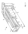
- reference numeral 1 generally designates the feeder for feeding a machine tool.
- the feeder 1 is composed of a frame that consists of a tubular beam 2 that has a rectangular cross-section and lies horizontally between two heads that are rigidly coupled thereto at the opposite ends.
- a side wall 3 is fixed to the beam 2, and posts 4 are fixed thereto in a cantilevered fashion in order to support panels 5 that form the lateral housing of the feeder.
- the posts 4 are shaped so as to form a right angle and have, at their top, an inclined surface 6 that constitutes the magazine from which the bars B are taken individually to be inserted in the guide of the feeder. Pick-up is performed by a singling lever system 7, which is not described in detail since it is fully conventional and does not relate to the present invention.
- the guide of the feeder can be of various kinds. In the described example, it is assumed that it is composed of two superimposed half-shells 8 and 9; the lower one 8 is fixed in a cantilevered fashion to the upper edge of the wall 3, which protrudes from the beam 2, by means of a profiled element 10.
- the half-shells 8 and 9 have mutually opposite cavities that form the channel 11 for guiding a bar toward the machine tool.
- the upper half-shell 9 is articulated to the lower half-shell 8 so that the edges of the two half-shells that are directed toward the loading surface 6 can be spaced or open in order to allow the insertion of a bar B in the channel 11 and then moved closer one another in order to close the channel and keep the bar guided during its advancement toward the machine tool.
- a bar pusher 12 which is actuated by means that are external to the guide, to which it is connected by means of a pair of bridges 13 and 14.
- the openable edges of the half-shells remain in any case spaced, in the guide closure position, by a slot 15 whose gap is wider than the bridges are thick.
- the slot 15 is enlarged for the sake of clarity.
- the ends of the bridges 13 and 14 that are external to the half-shells are rigidly coupled to a carriage, generally designated by the reference numeral 16, which is composed of two L-shaped brackets 17 and 18, with a first arm 19 that lies horizontally above the upper edge of the wall 3 and the profiled element 10 and a second arm 20 that runs vertically downward from the end of the first arm 19.
- the horizontal arms 19 and 20 are connected by a rod 21 for coupling the bridges 13 and 14 and respectively by a plate 22 that is flat and parallel to the wall 3.
- Two sliders 24 are rigidly coupled, with suitable spacer blocks 23 interposed, to the plate 22 in its upper part and are provided with grooves for slidingly engaging a horizontal rail 25 that has a dovetail cross-section and is fixed to the wall 3.
- the carriage 16 is provided in a lower region with additional arms 26 that extend toward the wall 3 and support additional sliders 27 for resting slidingly on said wall 3.
- the dimensions of the carriage 16 are such that it can slide in the axial compartment 28 comprised between the wall 3 and the housing 5.
- the armature winding 29 (also known as stator) of a linear motor 30 for moving the carriage 16 along the rail 25 is fixed to the wall 22 under the sliders 24.
- the inductor elements of the linear motor 30 that cooperate with the winding 29 are constituted by magnets forming an inductor bar 31, distributed on a first bar 32 (also known as magnetic track), which is fixed to the wall 3 below and horizontally with respect to the rail 25 in front of said winding 29.
- the characteristics of the linear motor 30 ensure a uniform advancement of the carriage 16 and of the bar pusher 12 and therefore a constant and progressive thrust on the bar to be fed into the lathe.
- the linear motor is capable of providing a precise dynamic response that allows perfect synchronization with the operating steps of the lathe.
- a barrier that closes the compartment 28 in an upward region is arranged above the sliders 24.
- Said barrier is constituted by a first strip 33, which is fixed to the top of the wall 3, and by a second strip 34, which is fixed to the top of the posts 4.
- the two strips 33, 34 protrude longitudinally toward each other and support respectively, along their opposite edges, a double brush 35 and a single or double brush 36, whose upper bristles engage between the bristles of the double brush 35.
- Figures 5 and 6 illustrate a feeder in which the linear motor comprises a second magnetic track, composed of a second bar 37 provided with permanent magnets.
- the second bar 37 is arranged opposite the first bar 32 and is rigidly coupled thereto, so as to form an interspace 38 along which the stator 29, supported by the arms 19 of the brackets 17 and 18, moves.
- FIGS 7 and 8 illustrate a third embodiment, in which the stator 29 is of the tubular type and is crossed by a longitudinal bar 39, which constitutes the inductor of the linear motor.
- the opposite ends of the bar 39 are rigidly coupled to supports 40 which are rigidly coupled to the wall 3.
- so-called retractable supports i.e., supports adapted to allow the passage of the stator 29 during the forward and return strokes of the carriage while continuing to support said carriage upstream and downstream, are used.
Landscapes
- Engineering & Computer Science (AREA)
- Mechanical Engineering (AREA)
- Turning (AREA)
Applications Claiming Priority (2)
| Application Number | Priority Date | Filing Date | Title |
|---|---|---|---|
| ITBO20020134 | 2002-03-20 | ||
| IT2002BO000134A ITBO20020134A1 (it) | 2002-03-20 | 2002-03-20 | Caricatore di barre per l'alimentazione di macchine utensili |
Publications (2)
| Publication Number | Publication Date |
|---|---|
| EP1346786A2 true EP1346786A2 (de) | 2003-09-24 |
| EP1346786A3 EP1346786A3 (de) | 2003-11-19 |
Family
ID=11439980
Family Applications (1)
| Application Number | Title | Priority Date | Filing Date |
|---|---|---|---|
| EP03004924A Withdrawn EP1346786A3 (de) | 2002-03-20 | 2003-03-07 | Stangenzuführvorrichtung zum Zuführen an Werkzeugmaschinen |
Country Status (3)
| Country | Link |
|---|---|
| US (1) | US20030180124A1 (de) |
| EP (1) | EP1346786A3 (de) |
| IT (1) | ITBO20020134A1 (de) |
Families Citing this family (1)
| Publication number | Priority date | Publication date | Assignee | Title |
|---|---|---|---|---|
| WO2007098489A2 (en) * | 2006-02-22 | 2007-08-30 | Kneebusch William C | Method and apparatus for feeding bars into a cutting lathe |
Family Cites Families (7)
| Publication number | Priority date | Publication date | Assignee | Title |
|---|---|---|---|---|
| CH446005A (fr) * | 1965-08-23 | 1967-10-31 | Esco Sa | Dispositif d'avance pour tour automatique |
| GB1288385A (de) * | 1969-02-07 | 1972-09-06 | ||
| US3703112A (en) * | 1970-06-11 | 1972-11-21 | Warner Swasey Co | Machine tool with bar feed control |
| CH636030A5 (de) * | 1979-02-08 | 1983-05-13 | Tornos Sa Fabrique De Machine | Stangenfoermigen werkstoff verarbeitender drehautomat. |
| IT1178975B (it) * | 1984-06-19 | 1987-09-16 | Bisiach & Carru | Struttura porta a carro porta le mobile su rotaie |
| IT1221384B (it) * | 1988-06-22 | 1990-06-27 | Iemca Spa | Dispositivo per l' introduzione di barre poligonali e sagomante nella pinza del mandrino di macchine utensili |
| US5535653A (en) * | 1993-09-08 | 1996-07-16 | J. F. Berns Company, Inc. | Bar stock supporting and feeding apparatus |
-
2002
- 2002-03-20 IT IT2002BO000134A patent/ITBO20020134A1/it unknown
-
2003
- 2003-03-07 EP EP03004924A patent/EP1346786A3/de not_active Withdrawn
- 2003-03-10 US US10/383,637 patent/US20030180124A1/en not_active Abandoned
Also Published As
| Publication number | Publication date |
|---|---|
| ITBO20020134A1 (it) | 2003-09-22 |
| ITBO20020134A0 (it) | 2002-03-20 |
| US20030180124A1 (en) | 2003-09-25 |
| EP1346786A3 (de) | 2003-11-19 |
Similar Documents
| Publication | Publication Date | Title |
|---|---|---|
| CN103722236B (zh) | 数控双头多根切割锯 | |
| US20180304331A1 (en) | Bending machine | |
| CN111156250B (zh) | 导轨顶面沉头孔边缘异物排出的直线导轨防尘结构 | |
| CN110695448B (zh) | 铝塑型材锯切设备 | |
| EP1346786A2 (de) | Stangenzuführvorrichtung zum Zuführen an Werkzeugmaschinen | |
| CN203599633U (zh) | 数控双头多根切割锯 | |
| TWI803708B (zh) | 刷子塞孔機以及用於塞孔的方法 | |
| AU619499B2 (en) | An automatic bookbinding machine | |
| CN116532997A (zh) | 一种全自动铝型材开料机 | |
| US20060185454A1 (en) | Linear guide unit | |
| CN210589739U (zh) | 一种木地板裁切机 | |
| CN109624257B (zh) | 一种管材加工设备及加工工艺 | |
| CN112935827A (zh) | 一种建筑模板连接件加工装置 | |
| US11862920B2 (en) | Contact loading assembly for electrical connector assembling machine | |
| CN114670011B (zh) | 一种隐藏轨的组装生产线 | |
| CN217799638U (zh) | 一种激光切管机 | |
| CN215545411U (zh) | 蛇形弯管切断机 | |
| US4366610A (en) | Device for inserting bars into tubes | |
| GB2125729A (en) | End-forming of timber strips and an end-forming woodworking machine | |
| CN211464683U (zh) | 一种可切割钢筋的板材切割机 | |
| CN210702557U (zh) | 一种3d打印设备用自动更换刀具装置 | |
| KR101620844B1 (ko) | 한옥창호 창살의 조립홈 가공장치 | |
| CN220859591U (zh) | 一种拉头安装机构 | |
| CN219598637U (zh) | 一种型材和转角的组装设备 | |
| CN119260460B (zh) | 一种智能机床用防护罩及使用方法 |
Legal Events
| Date | Code | Title | Description |
|---|---|---|---|
| PUAI | Public reference made under article 153(3) epc to a published international application that has entered the european phase |
Free format text: ORIGINAL CODE: 0009012 |
|
| AK | Designated contracting states |
Kind code of ref document: A2 Designated state(s): AT BE BG CH CY CZ DE DK EE ES FI FR GB GR HU IE IT LI LU MC NL PT RO SE SI SK TR |
|
| AX | Request for extension of the european patent |
Extension state: AL LT LV MK |
|
| PUAL | Search report despatched |
Free format text: ORIGINAL CODE: 0009013 |
|
| AK | Designated contracting states |
Kind code of ref document: A3 Designated state(s): AT BE BG CH CY CZ DE DK EE ES FI FR GB GR HU IE IT LI LU MC NL PT RO SE SI SK TR |
|
| AX | Request for extension of the european patent |
Extension state: AL LT LV MK |
|
| 17P | Request for examination filed |
Effective date: 20040323 |
|
| AKX | Designation fees paid |
Designated state(s): AT BE BG CH CY CZ DE DK EE ES FI FR GB GR HU IE IT LI LU MC NL PT RO SE SI SK TR |
|
| 18D | Application deemed to be withdrawn |
Effective date: 20061003 |
|
| STAA | Information on the status of an ep patent application or granted ep patent |
Free format text: STATUS: THE APPLICATION IS DEEMED TO BE WITHDRAWN |
|
| R18D | Application deemed to be withdrawn (corrected) |
Effective date: 20061003 |