EP1346264B1 - Analoge elektronische uhr mit vorrichtung zur zeitkorrektur nach einer mangelhaften energiezufuhr - Google Patents
Analoge elektronische uhr mit vorrichtung zur zeitkorrektur nach einer mangelhaften energiezufuhr Download PDFInfo
- Publication number
- EP1346264B1 EP1346264B1 EP01985360A EP01985360A EP1346264B1 EP 1346264 B1 EP1346264 B1 EP 1346264B1 EP 01985360 A EP01985360 A EP 01985360A EP 01985360 A EP01985360 A EP 01985360A EP 1346264 B1 EP1346264 B1 EP 1346264B1
- Authority
- EP
- European Patent Office
- Prior art keywords
- motor
- time
- electronic watch
- power source
- voltage
- Prior art date
- Legal status (The legal status is an assumption and is not a legal conclusion. Google has not performed a legal analysis and makes no representation as to the accuracy of the status listed.)
- Expired - Lifetime
Links
Images

Classifications
-
- G—PHYSICS
- G04—HOROLOGY
- G04G—ELECTRONIC TIME-PIECES
- G04G99/00—Subject matter not provided for in other groups of this subclass
-
- G—PHYSICS
- G04—HOROLOGY
- G04G—ELECTRONIC TIME-PIECES
- G04G19/00—Electric power supply circuits specially adapted for use in electronic time-pieces
- G04G19/08—Arrangements for preventing voltage drop due to overloading the power supply
Definitions
- the present invention relates to an electronic watch which comprises analogue display means consisting of at least one needle driven by at least one motor, a time base for controlling drive means of said motor, a rechargeable power source, motor stopping means acting in particular on said drive means and time counting means in synchronism with said analog display means for a sufficient supply voltage of the source.
- a watch comprising means for detecting insufficient power supply to the motor is known in particular from the document WO 98/33098 .
- This document presents an electronic watch comprising electrically driven and electronically controlled needles containing time data, a power source and means for detecting the insufficiency of this source. In case of insufficient power the needles are brought and maintained on reference positions programmed in advance in the electronic means.
- This watch has some disadvantages. Indeed, the hands of the watch are the reflection of the value of a counter of the electronic means. This is why it is necessary to bring the needles into a reference position, during a power failure, to force the value of this counter to a programmed reference value before the watch is switched on. Thus, this clock synchronized needles can no longer be used as a timer. It is therefore necessary to have a second counter that counts the time during a power failure. On the other hand, during normal operation of the watch, which represents the majority of the operating time, the two counters contain the same values. These two counters unnecessarily complicate the electronic means of the watch.
- EP-A-1 014 227 discloses an electronic watch according to the preamble of claim 1.
- the main purpose of the invention is therefore to overcome the drawbacks of the abovementioned prior art by providing an electronic watch which comprises simplified electronic means that do not require the programming of a reference value for the time-release following an insufficiency of time. 'food.
- the subject of the invention is an electronic watch of the type mentioned in the introduction, which is characterized in that, when a lack of power is detected by said stop means, said display means are stopped and the corresponding value of said counting means is stored in means of storage, said counting means continuing to operate, and in that time difference calculation means send, as soon as the supply is again sufficient, time difference signals between the stored value and the value of the means of counting said training means for the time setting of said analog display means.
- said motor stopping means are actuated for a first threshold voltage corresponding to the detection of a power failure of the motor and they are kept actuated as long as a second voltage, of threshold greater than the first voltage of threshold has not been reached by the power source, which avoids problems related to the variation of supply voltage due to load variations when stopping elements such as the engine.
- This second threshold voltage corresponds to a determined load level of the power source.
- the storage means may be composed in particular of a non-volatile memory.
- Figure 1 shows the elements of the watch necessary for the understanding of the invention.
- the electronic watch comprises analog display means 1 generally consisting of at least two hands 2. One serves to indicate the hours and the other the minutes. It is possible to provide a third needle for indicating, for example, seconds.
- the needles 2 are driven by at least one motor 3.
- the hour hand and the minute hand are driven by a stepping motor and that of the seconds is driven by another stepper motor. Indeed, for the sake of saving energy, the motor driving the seconds hand can be stopped earlier.
- a time base 4 makes it possible to define for each motor 3 the pitch for the advance of the needle 2 associated with said motor.
- the time base 4, generally used, consists in particular of a crystal oscillator, referenced 5 and 6, and different frequency divider stages 7 of the oscillator 6 to drive each motor 3 with the desired pitch.
- Drive means 8 or motors 3 are provided for this purpose.
- the motor 3 is powered by a rechargeable power source 9 of the accumulator or battery type.
- This power source 9 can be recharged in various ways, including the use of photovoltaic cells, oscillating weight, or by electrical contacts. The latter method will be used preferably to satisfy a need for fast and complete recharging.
- Voltage comparators 11 and 12 are placed at the output of the supply source 9. They receive as input a fraction of the supply voltage obtained by a voltage divider, for example a resistive bridge, and a voltage V ' S1 , respectively V ' S2 . These voltages are a reflection of the threshold voltages V S1 and V S2 (see FIGS. 2 to 4).
- V S1 corresponds to a voltage sufficient to ensure synchronization between the time indication of the analog display 1 and the pulses supplied by the time base 4 to the drive means of the motor 8.
- the value of this voltage is chosen with a safety factor in relation to the minimum voltage necessary for the correct operation of the motor 3.
- V S2 corresponds to a determined load level for which the load is deemed sufficient to restart the engine. The latter could still function properly below this voltage.
- This second threshold voltage also makes it possible to avoid the effects as discussed with reference to FIG.
- V ' S1 and V' S2 are achieved by means of a conventional circuit known to those skilled in the art.
- This circuit not shown, comprises means for supplying a reference voltage to which a resistive voltage divider bridge is applied, defining the two voltages V ' S1 and V' S2 . These two voltages are therefore lower than the threshold voltages V S1 and V S2 .
- the comparator 11 compares the fractional supply voltage with the reflection voltage V ' S1 , respectively V' S2 .
- These comparison means 11 and 12 are operational as long as the supply voltage is greater than a minimum voltage V OUT (see FIG. 4).
- switching means not shown, leaving only the comparator 11 active when discharging the power source 9, and conversely leaving the comparator 12 active when charging the power source 9.
- Stop means 14 of the engine retrieve the results of the comparisons. These means make it possible, in particular, to detect an insufficiency of supply of the source 9. According to the state of the power supply and according to the preceding state of the motor provided by a signal 13, these stop means 14 will send to the means of power supply. drive 8 a motor status control signal 15, which will be either an engine stop signal or a start signal of the engine. The evolution of these engine states as a function of the comparisons made by the comparators 11 and 12 will be studied in detail in FIG. 2.
- the means for stopping the engine are in particular connected to a reset circuit 17.
- This time reset circuit 17 is composed of at least one counter 18 for counting the time according to the pulses, received by the time base 4, storage means composed of at least one memory 19 for storing the contents of the counter 18 and means for calculating the time difference 20 allowing to obtain the offset 24 between the position of the hands 2 and the exact time.
- the counter 18 operates continuously as long as the power source 9 delivers a minimum voltage V OUT sufficient to supply the time base 4 and operate said counter 18. Below this voltage V OUT , no function is ensured. to work properly. In general, this voltage V OUT is substantially lower than the first threshold voltage V S1 , which leaves the user with a sufficient amount of time, for example, a minimum of several hours, to be aware of the insufficiency of feeding, the needles 2 being stopped. The user can then recharge the battery or battery 9 while keeping accurate time information.
- the motor 3 is stopped as well as the needles 2.
- the stop means 14 then send the information signal 16a concerning the stopping of the motor to a memory 19.
- the value then contained in the counter 18 is stored in the memory 19.
- a nonvolatile memory 19 is used.
- an information signal 16b is sent to the difference calculation means 20.
- these means 20 perform the subtraction between the current value 22 of the counter 18 and the stored value 23 in the memory 19
- the result obtained is in the form of time difference signals 21 which are sent to the driving means of the motor 8 in order to reset the hands 2 to the time. Needles 2 are brought on time by the shortest path.
- the drive means 8 control the rotation of the motor 3 in one direction or the other.
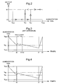
- FIG. 2 represents the operation of the motor stopping means 14 as a function of the comparisons made by the comparators 11 and 12 and as a function of the state of the motor 15, seen in FIG. 1.
- the supply voltage delivered by the source 9. This voltage can vary between 0 and V MAX .
- the zero voltage corresponds to the voltage delivered when the battery or the accumulator 9 is totally discharged.
- the voltage V MAX corresponds to the maximum voltage delivered when the battery or accumulator is fully charged.
- the voltage V OUT corresponds to the minimum voltage for which the data of the counter 18 is accurate.
- the voltages V S1 and V S2 correspond to the two threshold voltages whose associated reflective voltages V ' S1 and V' S2 make it possible to control the state of the motor.
- In ordinate is represented the state in which is the motor. If the state corresponds to A, the motor is stopped. If the state is M, the motor is running.
- V MAX the voltage delivered is V MAX .
- the energy supplied is sufficient, the motor is therefore running, that is to say in the M state.
- the battery or the accumulator 9 discharges.
- the supply voltage becomes lower than the threshold voltage V S1 , the energy supplied by the source is no longer sufficient to ensure synchronization between the time base 4 and the hourly indication of the hands 2.
- the means stopping of the motor 14 are actuated and the motor 3 is stopped via the drive means of the motor 8. The motor 3 goes to the state A.
- the hands 2 are also stopped.
- the value of the time counter 18 is stored, the counter continues to operate.
- the majority of the energy consumed by the device is the energy consumed by the engine.
- the motor 3 is restarted only from a second threshold voltage V S2 greater than V S1 and corresponding to a determined minimum charge level.
- the stop means 14 remain actuated, during charging, for a value between V S1 and V S2 , because the state of the engine is A.
- Figures 3 and 4 show a conventional discharge / recharge cycle of the power source 9 as a function of time, according to the prior art ( Figure 3) and according to the invention ( Figure 4).
- a device As described in the introduction of this description, a device, according to Figure 3, leads to the creation of a transitional period that we want to avoid.
- two reflective voltages V ' S1 and V' S2 associated with the threshold voltages V S1 and V S2 are used to manage the means for stopping the motor 14, which makes it possible to avoid the disadvantage, mentioned above, current in the devices of the prior art provided with battery or accumulator 9.
- V S2 a second threshold voltage V S2 greater than V S1 is provided.
- the value of V S2 is taken in such a way that it is greater than the voltage V S1 to which is added the overvoltage due to the stopping of the main consumer, that is to say, when the motor stops. 3.
- the power source 9 goes directly into a lower energy operating mode. Therefore, the discharge slope is much less pronounced between instants t1 and t2.
- the moment t2 represents the moment when the user realizes that the hands 2 of his watch are stopped and decides to recharge the battery or the accumulator 9.
- the recharge is represented between times t2 and t3.
Landscapes
- Physics & Mathematics (AREA)
- General Physics & Mathematics (AREA)
- Engineering & Computer Science (AREA)
- Power Engineering (AREA)
- Electromechanical Clocks (AREA)
Claims (5)
- Elektronische Uhr, die analoge Anzeigemittel (1), die aus wenigstens einem Zeiger (2) gebildet sind, der durch wenigstens einen Motor (3) angetrieben wird, eine Zeitbasis (4) zum Steuern der Antriebsmittel (8) des Motors, eine wiederaufladbare Versorgungsquelle (9), Mittel (14) zum Anhalten des Motors (3), die insbesondere auf die Antriebsmittel (8) einwirken, und Mittel (18) zum Zählen der Zeit synchron zu den analogen Anzeigemitteln (1) für eine ausreichende Versorgungsspannung umfasst, dadurch gekennzeichnet, dass ab der Erfassung einer unzureichenden Versorgung durch die Anhaltemittel (14) die Anzeigemittel (1) angehalten werden und der entsprechende Wert der Zählmittel (18) in Speichermitteln (19) gespeichert wird, wobei die Zählmittel (18) weiterhin arbeiten, und dass Zeitdifferenzberechnungsmittel (20) Signale (21) für eine Zeitdifferenz zwischen dem gespeicherten Wert und dem Wert der Zählmittel zu den Antriebsmitteln (8) schicken, um die analogen Anzeigemittel wieder auf die Zeit zu stellen, sobald die Versorgung erneut ausreicht.
- Elektronische Uhr nach Anspruch 1, dadurch gekennzeichnet, dass die Anhaltemittel (14) des Motors bei einer ersten entsprechenden Schwellenspannung (VS1) bei Erfassung einer unzureichenden Versorgung des Motors (3) betätigt werden und dass sie so lange im betätigten Zustand gehalten werden, wie eine zweite Schwellenspannung (VS2), die höher als die erste Schwellenspannung (VS1) ist, von der Versorgungsquelle nicht erreicht ist.
- Elektronische Uhr nach Anspruch 2, dadurch gekennzeichnet, dass die zweite Schwellenspannung (VS2) einem bestimmten Ladepegel der Versorgungsquelle (9) entspricht.
- Elektronische Uhr nach Anspruch 1, dadurch gekennzeichnet, dass die Anhaltemittel (14) während einer Zeitdauer, die ausreicht, um Wirkungen einer Ladungsänderung der Versorgungsquelle zu vermeiden, bei Erfassung einer unzureichenden Versorgung betätigt gehalten werden.
- Elektronische Uhr nach einem der Ansprüche 1 bis 4, dadurch gekennzeichnet, dass die Anzeigemittel (1) dann, wenn die Anhaltemittel (14) des Motors deaktiviert werden, auf dem kürzesten Weg wieder auf die Zeit gestellt werden.
Priority Applications (1)
| Application Number | Priority Date | Filing Date | Title |
|---|---|---|---|
| EP01985360A EP1346264B1 (de) | 2000-12-18 | 2001-11-29 | Analoge elektronische uhr mit vorrichtung zur zeitkorrektur nach einer mangelhaften energiezufuhr |
Applications Claiming Priority (4)
| Application Number | Priority Date | Filing Date | Title |
|---|---|---|---|
| EP00204579A EP1215545A1 (de) | 2000-12-18 | 2000-12-18 | Analoge elektronische Uhr mit Vorrichtung zur Zeitkorrektur nach einer mangelhaften Energiezufuhr |
| EP00204579 | 2000-12-18 | ||
| PCT/EP2001/014208 WO2002050617A1 (fr) | 2000-12-18 | 2001-11-29 | Montre electronique analogique ayant un dispositif de remise a l'heure suite a une insuffisance d'alimentation |
| EP01985360A EP1346264B1 (de) | 2000-12-18 | 2001-11-29 | Analoge elektronische uhr mit vorrichtung zur zeitkorrektur nach einer mangelhaften energiezufuhr |
Publications (2)
| Publication Number | Publication Date |
|---|---|
| EP1346264A1 EP1346264A1 (de) | 2003-09-24 |
| EP1346264B1 true EP1346264B1 (de) | 2007-08-01 |
Family
ID=8172442
Family Applications (2)
| Application Number | Title | Priority Date | Filing Date |
|---|---|---|---|
| EP00204579A Withdrawn EP1215545A1 (de) | 2000-12-18 | 2000-12-18 | Analoge elektronische Uhr mit Vorrichtung zur Zeitkorrektur nach einer mangelhaften Energiezufuhr |
| EP01985360A Expired - Lifetime EP1346264B1 (de) | 2000-12-18 | 2001-11-29 | Analoge elektronische uhr mit vorrichtung zur zeitkorrektur nach einer mangelhaften energiezufuhr |
Family Applications Before (1)
| Application Number | Title | Priority Date | Filing Date |
|---|---|---|---|
| EP00204579A Withdrawn EP1215545A1 (de) | 2000-12-18 | 2000-12-18 | Analoge elektronische Uhr mit Vorrichtung zur Zeitkorrektur nach einer mangelhaften Energiezufuhr |
Country Status (7)
| Country | Link |
|---|---|
| US (1) | US6934223B2 (de) |
| EP (2) | EP1215545A1 (de) |
| JP (1) | JP4554884B2 (de) |
| KR (1) | KR100880347B1 (de) |
| CN (1) | CN1222850C (de) |
| DE (1) | DE60129738T2 (de) |
| WO (1) | WO2002050617A1 (de) |
Families Citing this family (8)
| Publication number | Priority date | Publication date | Assignee | Title |
|---|---|---|---|---|
| US20050105400A1 (en) * | 2003-11-17 | 2005-05-19 | Tai Wai Luk | Electronic timepiece with analog display and a method of operating same |
| FR2867575B1 (fr) * | 2004-03-09 | 2006-05-19 | Brandt Ind | Procede de gestion d'un affichage d'une information horaire dans un appareil electrique |
| DE602006011129D1 (de) * | 2006-05-18 | 2010-01-28 | Microcomponents Ag | Analoge Anzeige und Uhr für Kraftfahrzeuge |
| JP4947180B2 (ja) * | 2010-04-12 | 2012-06-06 | カシオ計算機株式会社 | 電子時計 |
| CN103869692A (zh) * | 2012-12-17 | 2014-06-18 | 飞亚达(集团)股份有限公司 | 一种指针式时钟校时方法 |
| JP2016206057A (ja) * | 2015-04-24 | 2016-12-08 | セイコーエプソン株式会社 | 電子時計 |
| JP6597089B2 (ja) * | 2015-09-10 | 2019-10-30 | カシオ計算機株式会社 | アナログ電子時計及び指針早送り制御方法 |
| CN107239033A (zh) * | 2017-07-14 | 2017-10-10 | 成都天奥电子股份有限公司 | 一种卫星时钟指针指示方式 |
Family Cites Families (7)
| Publication number | Priority date | Publication date | Assignee | Title |
|---|---|---|---|---|
| JP3057340B2 (ja) * | 1992-03-12 | 2000-06-26 | セイコーインスツルメンツ株式会社 | 電子時計 |
| JP2564739B2 (ja) * | 1992-09-08 | 1996-12-18 | 株式会社精工舎 | 時 計 |
| DK0848842T3 (da) | 1996-06-26 | 1999-11-08 | Konrad Schafroth | Urværk |
| DE69738445T2 (de) * | 1996-08-01 | 2008-12-24 | Citizen Holdings Co., Ltd. | Elektronische zeitmessvorrichtung |
| CH691090A5 (fr) | 1997-01-23 | 2001-04-12 | Ebauchesfabrik Eta Ag | Montre comportant des moyens de détection de l'insuffisance de la source d'alimentation. |
| JPH11218587A (ja) * | 1997-11-25 | 1999-08-10 | Seiko Instruments Inc | 熱電素子付き電子時計 |
| JP3551861B2 (ja) * | 1998-12-11 | 2004-08-11 | セイコーエプソン株式会社 | 計時装置及びその制御方法 |
-
2000
- 2000-12-18 EP EP00204579A patent/EP1215545A1/de not_active Withdrawn
-
2001
- 2001-11-29 KR KR1020037007502A patent/KR100880347B1/ko not_active Expired - Fee Related
- 2001-11-29 US US10/450,853 patent/US6934223B2/en not_active Expired - Lifetime
- 2001-11-29 DE DE60129738T patent/DE60129738T2/de not_active Expired - Lifetime
- 2001-11-29 WO PCT/EP2001/014208 patent/WO2002050617A1/fr active IP Right Grant
- 2001-11-29 EP EP01985360A patent/EP1346264B1/de not_active Expired - Lifetime
- 2001-11-29 CN CNB018207405A patent/CN1222850C/zh not_active Expired - Fee Related
- 2001-11-29 JP JP2002551651A patent/JP4554884B2/ja not_active Expired - Fee Related
Also Published As
| Publication number | Publication date |
|---|---|
| CN1481520A (zh) | 2004-03-10 |
| JP4554884B2 (ja) | 2010-09-29 |
| KR100880347B1 (ko) | 2009-01-28 |
| EP1215545A1 (de) | 2002-06-19 |
| US6934223B2 (en) | 2005-08-23 |
| EP1346264A1 (de) | 2003-09-24 |
| WO2002050617A1 (fr) | 2002-06-27 |
| JP2004516482A (ja) | 2004-06-03 |
| CN1222850C (zh) | 2005-10-12 |
| US20040027925A1 (en) | 2004-02-12 |
| DE60129738D1 (de) | 2007-09-13 |
| KR20030059313A (ko) | 2003-07-07 |
| DE60129738T2 (de) | 2008-04-30 |
Similar Documents
| Publication | Publication Date | Title |
|---|---|---|
| EP0822470B1 (de) | Elektronisches Uhrwerk, das einen Generator enthält, der von einer Zugfeder getrieben wird | |
| EP1346264B1 (de) | Analoge elektronische uhr mit vorrichtung zur zeitkorrektur nach einer mangelhaften energiezufuhr | |
| US6956794B2 (en) | Electronically controlled timepiece, and power supply control method and time correction method therefore | |
| EP0022270B1 (de) | Stellungsdetektor für einen Schrittmotor | |
| EP0744675B1 (de) | Zeitmessinstrument insbesondere elektrische Armbanduhr analoger Art | |
| EP1857893B1 (de) | Analoge Anzeige und Uhr für Kraftfahrzeuge | |
| EP0135104B1 (de) | Verfahren und Vorrichtung zum Ansteuern eines Schrittmotors | |
| CH690523A5 (fr) | Pièce d'horlogerie comportant une génératrice d'énergie électrique. | |
| EP1544692B1 (de) | Elektromechanische Uhr, die mit einer Gangreserveanzeige ausgerüstet ist | |
| EP1247145B1 (de) | Uhr die eine vorrichtung zur anzeige des zustandes der batterie aufweist | |
| EP1739511B1 (de) | Verfahren zur Synchronisierung einer analogen Anzeige und eines flüchtigen Zähler in einer Uhr | |
| EP0954770B1 (de) | Uhr mit detektions- und sparvorrichtungen im falle von nicht ausreichender energieversorgung | |
| EP0203330B1 (de) | Elektronisches Uhrwerk mit Detektion für den Ablauf der Lebensdauer der Batterie | |
| EP0875807B1 (de) | Elektronisches Uhrwerk gespeist von einem Generator, der durch eine mechanische Energiequelle angetrieben wird | |
| EP0140089B1 (de) | Verfahren zur Steuerung eines Schrittmotors | |
| EP0028414A1 (de) | Zeitmesser mit einer Vorrichtung zum Speichern | |
| WO2014012790A1 (fr) | Procede de gestion ameliore d'un appareil electronique | |
| EP0848306B1 (de) | Zeitmessgerät mit einem Generator zur Erzeugung elektrischer Energie | |
| EP1014230B1 (de) | Zeitmessgerät mit Generator zur Erzeugung elektrischer Energie | |
| EP3299906A1 (de) | Elektronische uhr mit zwei zeigern vom analogen typ | |
| FR2668866A1 (fr) | Procede de commande d'un moteur pas a pas et dispositif pour la mise en óoeuvre de ce procede. | |
| EP0190591A1 (de) | Motorwerk geeignet für hohe Geschwindigkeit | |
| CH712944A2 (fr) | Pièce d'horlogerie électronique à deux aiguilles du type analogique. |
Legal Events
| Date | Code | Title | Description |
|---|---|---|---|
| PUAI | Public reference made under article 153(3) epc to a published international application that has entered the european phase |
Free format text: ORIGINAL CODE: 0009012 |
|
| 17P | Request for examination filed |
Effective date: 20030718 |
|
| AK | Designated contracting states |
Kind code of ref document: A1 Designated state(s): AT BE CH CY DE DK ES FI FR GB GR IE IT LI LU MC NL PT SE TR |
|
| RIN1 | Information on inventor provided before grant (corrected) |
Inventor name: GUANTER, JEAN-CHARLES Inventor name: MARTIN, JEAN-CLAUDE |
|
| RIN1 | Information on inventor provided before grant (corrected) |
Inventor name: MARTIN, JEAN-CLAUDE Inventor name: GUANTER, JEAN-CHARLES |
|
| RBV | Designated contracting states (corrected) |
Designated state(s): CH DE FR GB LI |
|
| GRAP | Despatch of communication of intention to grant a patent |
Free format text: ORIGINAL CODE: EPIDOSNIGR1 |
|
| GRAS | Grant fee paid |
Free format text: ORIGINAL CODE: EPIDOSNIGR3 |
|
| GRAA | (expected) grant |
Free format text: ORIGINAL CODE: 0009210 |
|
| AK | Designated contracting states |
Kind code of ref document: B1 Designated state(s): CH DE FR GB LI |
|
| REG | Reference to a national code |
Ref country code: GB Ref legal event code: FG4D Free format text: NOT ENGLISH |
|
| REG | Reference to a national code |
Ref country code: CH Ref legal event code: EP |
|
| REF | Corresponds to: |
Ref document number: 60129738 Country of ref document: DE Date of ref document: 20070913 Kind code of ref document: P |
|
| REG | Reference to a national code |
Ref country code: CH Ref legal event code: NV Representative=s name: ICB INGENIEURS CONSEILS EN BREVETS SA |
|
| GBT | Gb: translation of ep patent filed (gb section 77(6)(a)/1977) |
Effective date: 20071017 |
|
| PLBE | No opposition filed within time limit |
Free format text: ORIGINAL CODE: 0009261 |
|
| STAA | Information on the status of an ep patent application or granted ep patent |
Free format text: STATUS: NO OPPOSITION FILED WITHIN TIME LIMIT |
|
| 26N | No opposition filed |
Effective date: 20080506 |
|
| PGFP | Annual fee paid to national office [announced via postgrant information from national office to epo] |
Ref country code: GB Payment date: 20091102 Year of fee payment: 9 |
|
| GBPC | Gb: european patent ceased through non-payment of renewal fee |
Effective date: 20101129 |
|
| PG25 | Lapsed in a contracting state [announced via postgrant information from national office to epo] |
Ref country code: GB Free format text: LAPSE BECAUSE OF NON-PAYMENT OF DUE FEES Effective date: 20101129 |
|
| REG | Reference to a national code |
Ref country code: FR Ref legal event code: PLFP Year of fee payment: 15 |
|
| PGFP | Annual fee paid to national office [announced via postgrant information from national office to epo] |
Ref country code: DE Payment date: 20151022 Year of fee payment: 15 |
|
| PGFP | Annual fee paid to national office [announced via postgrant information from national office to epo] |
Ref country code: FR Payment date: 20151023 Year of fee payment: 15 |
|
| REG | Reference to a national code |
Ref country code: DE Ref legal event code: R119 Ref document number: 60129738 Country of ref document: DE |
|
| REG | Reference to a national code |
Ref country code: FR Ref legal event code: ST Effective date: 20170731 |
|
| PG25 | Lapsed in a contracting state [announced via postgrant information from national office to epo] |
Ref country code: FR Free format text: LAPSE BECAUSE OF NON-PAYMENT OF DUE FEES Effective date: 20161130 |
|
| PG25 | Lapsed in a contracting state [announced via postgrant information from national office to epo] |
Ref country code: DE Free format text: LAPSE BECAUSE OF NON-PAYMENT OF DUE FEES Effective date: 20170601 |
|
| PGFP | Annual fee paid to national office [announced via postgrant information from national office to epo] |
Ref country code: CH Payment date: 20201022 Year of fee payment: 20 |