EP1345716B1 - Feeder comprising a tubular body - Google Patents
Feeder comprising a tubular body Download PDFInfo
- Publication number
- EP1345716B1 EP1345716B1 EP01998419A EP01998419A EP1345716B1 EP 1345716 B1 EP1345716 B1 EP 1345716B1 EP 01998419 A EP01998419 A EP 01998419A EP 01998419 A EP01998419 A EP 01998419A EP 1345716 B1 EP1345716 B1 EP 1345716B1
- Authority
- EP
- European Patent Office
- Prior art keywords
- feeder
- casting
- tubular body
- feeder system
- mandrel
- Prior art date
- Legal status (The legal status is an assumption and is not a legal conclusion. Google has not performed a legal analysis and makes no representation as to the accuracy of the status listed.)
- Expired - Lifetime
Links
Images
Classifications
-
- B—PERFORMING OPERATIONS; TRANSPORTING
- B22—CASTING; POWDER METALLURGY
- B22C—FOUNDRY MOULDING
- B22C9/00—Moulds or cores; Moulding processes
- B22C9/08—Features with respect to supply of molten metal, e.g. ingates, circular gates, skim gates
- B22C9/084—Breaker cores
Landscapes
- Engineering & Computer Science (AREA)
- Mechanical Engineering (AREA)
- Molds, Cores, And Manufacturing Methods Thereof (AREA)
- Continuous Casting (AREA)
- Processing And Handling Of Plastics And Other Materials For Molding In General (AREA)
- Orthopedics, Nursing, And Contraception (AREA)
- Surgical Instruments (AREA)
- Massaging Devices (AREA)
- Casting Or Compression Moulding Of Plastics Or The Like (AREA)
- Devices For Post-Treatments, Processing, Supply, Discharge, And Other Processes (AREA)
- Hydroponics (AREA)
Abstract
Description
Die Erfindung betrifft ein Speisersystem für ein Gussstück mit einem Speiser(kopf) und einem rohrähnlichen Körper.The invention relates to a feeder system for a casting with a feeder (head) and a tube-like body.
Bei der Herstellung von Formteilen in der Gießerei wird flüssiges Metall in eine Gießform eingefüllt. Beim Erstarrungsvorgang verringert sich das Volumen des eingefüllten Materials. Daher werden regelmäßig sog. Speiser, d.h. offene oder geschlossene Räume in oder an der Gießform, eingesetzt, um das Volumendefizit bei der Erstarrung des Gussstücks auszugleichen und eine Lunkerbildung im Gussstück zu verhindern. Dazu sind die Speiser mit dem Gussstück bzw. mit dem gefährdeten Gussstückbereich verbunden und gewöhnlich oberhalb bzw. an der Seite des Formhohlraums angeordnet.In the production of molded parts in the foundry, liquid metal is poured into a casting mold. During the solidification process, the volume of the filled material is reduced. Therefore, so-called feeders, i. open or closed spaces in or on the mold, used to compensate for the volume deficit in the solidification of the casting and to prevent voids in the casting. For this purpose, the feeders are connected to the casting or to the vulnerable casting area and are usually arranged above or on the side of the mold cavity.
Im Stand der Technik sind zahlreiche Speiser bekannt. Beispielsweise beschreibt die DE 196 42 838 A1 einen Speiser für ein metallisches Gussstück in der Form einer Glocke mit einem eingezogenen Glockenrand, der von einem aufgesetzten flachen Ringteil gebildet wird.Numerous feeders are known in the art. For example, DE 196 42 838 A1 describes a feeder for a metallic casting in the form of a bell with a recessed bell rim formed by an attached flat ring member.
Die DE 41 19 192 A1 beschreibt einen federnden Dorn zum Halten von Speisern. Dabei werden die Speisereinsätze auf einem mit der Gießform verbundenen Dorn aufgesteckt und vorzugsweise im Oberkasten eingeformt. Da das Material der Speiser sehr nachgiebig ist und der Sanddruck beim Formen in der Formanlage leicht zu einer Beschädigung des eingesetzten Speisers führen kann, ist es bekannt, den Dorn federnd axial beweglich auszubilden, so dass der eingeformte Speiser dem Sanddruck in Richtung auf das Modell hin ausweichen kann.DE 41 19 192 A1 describes a resilient mandrel for holding feeders. The feeder inserts are attached to a mandrel connected to the mold and preferably formed in the upper box. Since the material of the feeder is very yielding and the sand pressure during molding in the molding plant can easily lead to damage of the feeder used, it is known to form the spring resiliently axially movable, so that the molded feeder the sand pressure in the direction of the model can dodge.
Die DE 42 00 183 A1 betrifft einen zweiteiligen Speiser mit einem am Gussstück anliegenden Speiserfuß aus einem exothermen Material und mit einem an den Speiserfuß anzusetzenden, den Hohlraum aufweisenden Oberteil, wobei der Speiserfuß eine langgestreckt-ovale Verbindungsöffnung zum Gussstück aufweist und die ovale Verbindungsöffnung zum Durchtritt eines den Speiser am Gießmodell während des Formvorgangs fixierenden Dorns eingerichtet ist.DE 42 00 183 A1 relates to a two-part feeder with an adjacent to the casting Feiserfuß of an exothermic material and to be applied to the Feiserfuß, the cavity having upper part, wherein the Feiserfuß has an elongated-oval connection opening to the casting and the oval connection opening to the passage a spinner is fixed to the casting model during the molding operation.
Normalerweise werden die Speiser etwa in Anschnitthöhe angeordnet und außerdem mit einem wärmeisolierenden Material bzw. exothermen Massen so ausgerüstet, dass die im Speiser befindliche Schmelze später als das Gussstück selbst erstarrt. Nach der Erstarrung bleibt der Speiser mit dem Gussstück verbunden, so dass der Restspeiser anschließend abgetrennt werden muss. Die saubere und leichte Abtrennung des Speisers vom Gussstück ist dabei in vielen Fällen problematisch. Regelmäßig muss nach dem Abtrennen des Speisers die Gussoberfläche noch entgratet und geglättet werden. Das ist ein aufwendiger und entsprechend teurer Arbeitsgang, der auch zu Beschädigungen der Oberfläche des Gussstücks an der Verbindungsstelle mit dem Speiser führen kann. Um derartige Beschädigungen zu verringern und das Abtrennen des Speisers zu erleichtern, werden häufig sog. Brechkerne (auch Brechkante, Sandleiste oder Einschnürkern genannt) vorgesehen. Diese werden zwischen dem Speiser und der Gießform angebracht und benötigen entsprechende Aufsatzflächen.Normally, the feeders are arranged approximately at the gate height and also equipped with a heat-insulating material or exothermic masses so that the melt located in the feeder solidifies later than the casting itself. After solidification, the feeder remains connected to the casting so that the remainder of the feeder must then be separated. The clean and easy separation of the feeder from the casting is problematic in many cases. Regularly, after cutting off the feeder, the casting surface must still be deburred and smoothed. This is a complex and correspondingly expensive operation, which can also lead to damage to the surface of the casting at the junction with the feeder. In order to reduce such damage and to facilitate the separation of the feeder, so-called refractive cores (also called breaking edge, sanding strip or constrictor core) are frequently provided. These are placed between the feeder and the mold and require appropriate attachment surfaces.
Insgesamt sind die bekannten Speiser entweder verhältnismäßig aufwendig in ihrem Aufbau bzw. der Handhabung bei der Herstellung der Gießform und/oder gewährleisten kein leichtes und präzises Abtrennen des Restspeisers vom fertigen Gussstück oder benötigen eine relativ große Aufsatzfläche.Overall, the known feeders are either relatively expensive in their construction or handling in the production of the mold and / or ensure no easy and precise separation of the residual feed from the finished casting or require a relatively large top surface.
Ziel der vorliegenden Erfindung war es somit, ein Speisersystem bereitzustellen, das die Nachteile des Standes der Technik vermeidet und insbesondere einfach aufgebaut ist, leicht an der Gießform angebracht bzw. aufgeformt werden kann, nur geringe Aufsatzflächen benötigt und dennoch eine präzise positionierte Brechkante unmittelbar am Gusstück zum leichten und sicheren Abtrennen des Restspeisers vom fertigen Gussstück ermöglicht.The aim of the present invention was thus to provide a feeder system which avoids the disadvantages of the prior art and in particular has a simple structure, can be easily attached to the casting mold or formed, only requires small attachment surfaces and still requires a precisely positioned breaking edge directly on the casting allows easy and safe separation of the residual feed from the finished casting.
Diese Aufgabe wird durch ein Speisersystem gemäß Anspruch 1 gelöst. Vorteilhafte Ausführungsformen sind in den Unteransprüchen angegeben.This object is achieved by a feeder system according to
Vorliegend umfasst der Begriff Speiser jegliche im Stand der Technik bekannte bzw. dem Fachmann geläufige Form von Speisern, Speiserumhüllungen, Speisereinsätzen und Speiserkappen sowie Heizkissen.In the present case, the term feeder includes any known in the art or familiar to the expert form of feeders, feeder covers, feeder inserts and feeder caps and heating pads.
Die vorliegende Erfindung ist prinzipiell für alle Arten von Speisern brauchbar, bei denen der rohrähnliche Körper in der nachstehend angegebenen Weise angeordnet werden kann.The present invention is in principle useful for all types of feeders in which the tube-like body can be arranged in the manner indicated below.
Insbesondere ist die vorliegende Erfindung für sog. Mini-Speiser geeignet, die herkömmlich mit Brechkern oder durch Zuhilfenahme eines Federdorns aufgeformt werden.In particular, the present invention is suitable for so-called. Mini-feeder, which are conventionally formed with breaker core or by using a spring mandrel.
Das erfindungsgemäße Speisersystem besteht aus mindestens zwei Teilen. Zum einen ist auf der vom Gussstück abgewandten Seite ein Speiser bzw. Speiserkopf vorhanden, der einen Hohlraum zur Aufnahme des flüssigen Metalls während des Gießens bereitstellt.The feeder system according to the invention consists of at least two parts. On the one hand, it is on the side facing away from the casting Side of a feeder or head is provided, which provides a cavity for receiving the liquid metal during casting.
Zum Gussstück hin schließt sich ein rohrähnlicher Körper an, der, direkt oder indirekt, den vom Speiserkopf gebildeten Hohlraum mit dem Hohlraum der Gussform verbindet.Towards the casting, a tube-like body connects, which connects, directly or indirectly, the cavity formed by the feeder head with the cavity of the mold.
Der rohrähnliche Körper kann jede beliebige und im Einzelfall geeignete Länge, Wandstärke und Durchmesser aufweisen. Die Wandstärke wird in Abhängigkeit von dem verwendeten Material in der Regel zwischen 0,1 mm und 10 mm, insbesondere zwischen 0,3 mm und 5 mm, besonders bevorzugt 0,3 mm bis 0,5 mm, liegen. Die optimalen Abmessungen können im Einzelfall anhand routinemäßiger Versuche bestimmt werden bzw. sind dem Fachmann aufgrund seiner Erfahrungen bekannt. Die Wandstärken variieren auch aufgrund des Materials und können z.B. für Stahlblech und bei Verwendung eines Federdorn-Minispeisers bei etwa 0,3 mm bis 0,5 mm liegen.The tube-like body may have any length and wall thickness and diameter suitable in the individual case. The wall thickness, depending on the material used, is generally between 0.1 mm and 10 mm, in particular between 0.3 mm and 5 mm, particularly preferably 0.3 mm to 0.5 mm. The optimum dimensions can be determined on a case-by-case basis by means of routine tests or are known to the person skilled in the art on the basis of his experience. The wall thicknesses also vary due to the material and may be e.g. for sheet steel and when using a spring mandrel minispeiser at about 0.3 mm to 0.5 mm.
In der Regel weist der rohrähnliche Körper eine Länge zwischen etwa 15 und etwa 300 mm, insbesondere zwischen etwa 35 und etwa 100 mm auf. Die Länge des rohrähnlichen Körpers wird bei einer erfindungsgemäßen Ausführungsform so gewählt, dass mindestens der Abstand zwischen dem Speiser (vor dem Formen, ggf. auf dem Dorn) und dem Gussstück überbrückt wird.As a rule, the tube-like body has a length of between about 15 and about 300 mm, in particular between about 35 and about 100 mm. The length of the tube-like body is chosen in an embodiment according to the invention so that at least the distance between the feeder (before molding, possibly on the mandrel) and the casting is bridged.
Der Innendurchmesser des rohrähnlichen Körpers kann im Prinzip beliebig gewählt werden, wobei die Öffnung groß genug sein sollte, um das Fließen der Schmelze in bzw. aus dem Speiser während des Gieß- und Erstarrungsvorgangs zu gewährleisten. Der Durchmesser des rohrähnlichen Körpers orientiert sich in der Regel, jedoch nicht zwingend, am Speiser-Innendurchmesser, da nach einer Ausführungsform der vorliegenden Erfindung der rohrähnliche Körper in den Speiser(kopf) eingepasst bzw. eingesteckt wird. Es ist jedoch auch eine andersartige Anbringung am oder im Speiser(kopf) möglich.The inner diameter of the tube-like body can in principle be chosen arbitrarily, wherein the opening should be large enough to ensure the flow of the melt into and out of the feeder during the casting and solidification process. The diameter of the tube-like body is usually oriented, but not necessarily, on the feeder inner diameter, as according to one embodiment of the present invention Invention, the tube-like body in the feeder (head) is fitted or plugged. However, it is also a different attachment to or in the feeder (head) possible.
Der rohrähnliche Körper kann eine beliebige Querschnittsform aufweisen, insbesondere eine runde, ovale bzw. vier- oder mehreckige Geometrie.The tubular body may have any cross-sectional shape, in particular a round, oval or polygonal or polygonal geometry.
Nach einer Ausführungsform der vorliegenden Erfindung handelt es sich bei dem rohrähnlichen Körper um ein Rohr mit einem über die gesamte Länge im wesentlichen einheitlichen Querschnitt. Vorzugsweise liegt das Verhältnis von Wandstärke zum Gesamtdurchmesser des Rohres zwischen etwa 1:2 und 1:200, insbesondere 1:5 bis 1:120 und besonders bevorzugt 1:10 bis 1:100. Das Verhältnis von Länge zu Gesamtdurchmesser des Rohres liegt vorzugsweise zwischen etwa 1:4 und 15:1, insbesondere 1:1 und 6:1. Insbesondere richten sich die Verhältnisse nach Speiser- und Gießformgeometrie.According to one embodiment of the present invention, the tube-like body is a tube with a substantially uniform cross-section over its entire length. Preferably, the ratio of wall thickness to the overall diameter of the tube is between about 1: 2 and 1: 200, in particular 1: 5 to 1: 120, and particularly preferably 1:10 to 1: 100. The ratio of length to overall diameter of the tube is preferably between about 1: 4 and 15: 1, in particular 1: 1 and 6: 1. In particular, the ratios depend on the shape of the feeder and the casting mold.
Der Speiser bzw. Speiserkopf kann aus jedem im Stand der Technik bekannten isolierenden und/oder exothermen Material gebildet sein, um sicherzustellen, dass die im Speiser befindliche Schmelze später als das Gussstück selbst erstarrt. Beispielsweise kann der Speiser aus den in der DE 199 25 167 der gleichen Anmelderin offenbarten exothermen Speisermassen hergestellt werden.The feeder head may be formed of any insulating and / or exothermic material known in the art to ensure that the melt in the feeder solidifies later than the casting itself. For example, the feeder can be prepared from the exothermic feeder compositions disclosed in DE 199 25 167 of the same Applicant.
Der rohrähnliche Körper kann aus jedem geeigneten Werkstoff, der eine entsprechende Festigkeit aufweist und keine störenden Reaktionen auf das zu speisende Gussstück ausübt, gebildet werden. Diese Materialien sind dem einschlägigen Fachmann bekannt und umfassen beispielsweise Metall, Kunststoff, Pappe, Keramik oder ähnliche Materialien.The tube-like body may be formed of any suitable material which has a corresponding strength and does not exert any disturbing reactions on the casting to be fed. These materials are known to those skilled in the art and include, for example, metal, plastic, cardboard, ceramics or similar materials.
Nach einer bevorzugten Ausführungsform besteht der rohrähnliche Körper aus einem dem Gussprogramm ähnlichen Werkstoff, wie Aluminium oder Eisenblech.According to a preferred embodiment, the tube-like body consists of a casting program similar material, such as aluminum or iron sheet.
Der rohrähnliche Körper liegt bei einer vorteilhaften erfindungsgemäßen Ausführungsform mit dem Aussenumfang eng am Speiser bzw. Speiserkopf an und ist vorzugsweise mit dem Fachmann auf diesem Gebiet geläufigen Mitteln am Speiser(kopf) befestigt, z.B. mittels eines Klebstoffs wie Heißkleber oder Wasserglas, durch einen Keil oder mittels Passung. Er kann auch einfach in den Speiser(kopf) eingesteckt sein.The tube-like body is in an advantageous embodiment of the present invention with the outer circumference closely to the feeder or feeder head and is preferably attached to the feeder (head) by means known to those skilled in the art, e.g. by means of an adhesive such as hot glue or water glass, by a wedge or by means of fit. He can also simply be plugged into the feeder (head).
Nach einer weiteren bevorzugten Ausführungsform der Erfindung ist der rohrähnliche Körper jedoch gegenüber dem Speiser bzw. Speiserkopf und/oder dem Gussstück bzw. dem Formhohlkörper zumindest innerhalb gewisser Grenzen beweglich. Dadurch kann einerseits ein besonders unkompliziertes Anbringen des Speisers gewährleistet werden, und zum anderen eine optimale Positionierung der Brechkante durch die während des Anformens bzw. Verdichtens des Formstoffs erfolgende Verschiebung zwischen Speiser und rohrähnlichem Körper bzw. rohrähnlichem Körper und Gussstück bewirkt werden.According to a further preferred embodiment of the invention, however, the tube-like body is movable relative to the feeder or feeder head and / or the casting or the hollow body at least within certain limits. As a result, on the one hand, a particularly uncomplicated attachment of the feeder can be ensured, and on the other hand an optimal positioning of the breaking edge can be effected by the displacement occurring between the feeder and the tube-like body or casting during the molding or compacting of the molding material.
So lässt sich aufgrund der Verdichtung des Formstoffs und der entsprechenden Relativverschiebung zwischen Speiser bzw. rohrähnlichem Körper und dem Gussstück bzw. Formhohlkörper der Abstand zwischen dem rohrähnlichen Körper und dem Gussstück vor dem Formen leicht so einstellen, dass nach dem Formen bzw. der Verdichtung des Formstoffs der rohrähnliche Körper eine optimal positionierte Brechkante ausbildet, die möglichst nahe an dem fertigen Gussstück liegt.Thus, due to the compaction of the molding material and the relative displacement between the feeder or tubular body and the casting or hollow body, the distance between the pipe-like body and the casting can be easily adjusted prior to molding such that after molding or densification of the molding material the tube-like body forms an optimally positioned crushing edge which is as close as possible to the finished casting.
Erfindungsgemäß Verjüngt sich der rohrähnliche Körper zum Gussstück zugewandten Ende hin oder weist einen sich verjüngenden Abschnitt oder eine Verengung des Innendurchmessers auf.According to the invention, the tube-like body tapers towards the casting-facing end or has a tapering section or a narrowing of the inner diameter.
Nach einer bevorzugten erfindungsgemäßen Ausführungsform verjüngt sich der rohrähnliche Körper zum Gussstück hin und bildet direkt am Übergang zur Gussform bzw. in unmittelbarer Nähe eine Brechkante aus. Natürlich kann nach einer Ausführungsform der Erfindung auch nur ein bestimmter Abschnitt, vorzugsweise der dem Gussstück zugewandte Abschnitt, eine Verjüngung oder eine Verengung des (Innen) durchmessers aufweisen. Somit dient der rohrähnliche Körper einerseits der Bereitstellung eines aufformbaren Speiserhalses und andererseits der Bereitstellung einer präzisen und fest positionierten Brechkante. Die Brechkante ist vorzugsweise als eine Einschnürung der Öffnung bzw. des Innnendurchmessers am oder in der Nähe des dem Gussstück zugewandten Ende des rohrähnlichen Körpers vorgesehen.According to a preferred embodiment of the invention, the tube-like body tapers toward the casting and forms a breaking edge directly at the transition to the casting mold or in the immediate vicinity. Of course, according to an embodiment of the invention, only a certain portion, preferably the portion facing the casting, may have a taper or a constriction of the (inner) diameter. Thus, on the one hand, the tube-like body serves to provide a deformable neck of the feeder and, on the other hand, to provide a precise and firmly positioned breaking edge. The breaking edge is preferably provided as a constriction of the opening or the inside diameter at or in the vicinity of the casting-facing end of the tube-like body.
Des weiteren kann, wie vorstehend ausgeführt, durch die Dimensionierung des rohrähnlichen Körpers die Lage und Ausprägung der Brechkante optimiert werden, z.B. durch Verwendung eines verhältnismäßig schmalen Rohres mit kleinem Durchmesser oder eine entsprechende Anordnung des Speiser bzw. Speiserkopfes, so dass dieser nach dem Anformen bzw. Verdichten des Formstoffs recht nahe (doch nicht direkt auf dem) Gussstück liegt.Furthermore, as stated above, the dimensioning of the tube-like body optimizes the position and shape of the breaking edge, for example by using a relatively narrow tube with a small diameter or a corresponding arrangement of the feeder or feeder head, so that the latter after molding or Compressing the molding material quite close (yet not directly on the) casting lies.
Nach einer bevorzugten Ausführungsform umfasst das erfindungsgemäße Speisersystem, wie vorstehend erwähnt, weiterhin einen Dorn, insbesondere einen Federdorn.According to a preferred embodiment, the feeder system according to the invention, as mentioned above, further comprises a mandrel, in particular a spring mandrel.
Der mit dem Rohr (rohrähnlichen Körper) verbundene Speiser wird durch den Federdorn entsprechend hochgehalten. Dabei steht das Rohr auf der Form bzw. auf dem angeschrägten Grund des Federdorns auf. Während des Formvorgangs wird der Speiser über das Rohr nach unten in die entsprechende Endposition durch den Federdorn geführt. Das Rohr bleibt fest in der ursprünglichen Position. So wird sichergestellt, dass unmittelbar am Gussstück eine definierte Brechkante bereitgestellt wird.The feeder connected to the pipe (pipe-like body) is held up by the spring mandrel accordingly. The tube stands on the form or on the beveled base of the spring mandrel. During the molding process, the feeder is guided down the pipe to the corresponding end position by the spring mandrel. The tube remains firmly in the original position. This ensures that a defined breaking edge is provided directly on the casting.
Dabei kann im Rahmen der vorliegenden Erfindung jeder dem Fachmann als geeignet erscheinende Kern, Dorn oder Federdorn verwendet werden. Zum Gussstück hin kann der rohrähnliche Körper entweder vollständig über den Federdorn greifen, oder auf dessen Fuß aufstehen. In beiden Fällen wird (direkt bzw. indirekt) eine Verbindung zwischen dem Formhohlraum und dem rohrähnlichen Körper hergestellt.In the context of the present invention, any core, mandrel or spring mandrel that appears suitable for the person skilled in the art can be used. Towards the casting, the tube-like body can either grip completely over the spring mandrel or stand up on its base. In both cases, a connection is made (directly or indirectly) between the mold cavity and the tube-like body.
Nach einer weiteren vorteilhaften erfindungsgemäßen Ausführungsform kann der rohrähnliche Körper als Federdorn- bzw. Führungsdornersatz verwendet werden. Der Speiser wird dabei über den rohrähnlichen Körper, der auf der Gussform aufsteht, geführt. Zentriert wird ggf. über einen feststehenden Dorn, der unterschiedlich lang sein kann. Vorzugsweise weist der feststehende Dorn maximal die Länge des rohrähnlichen Körpers auf. In vielen Fällen kann es jedoch vorteilhaft sein, dass der feststehende Dorn kürzer als der rohrähnliche Körper ist und letzterer zumindest teilweise über den feststehenden Dorn geschoben wird. Während des Verdichtens schiebt sich dann der Speiser über den rohrähnlichen Körper. Nach einer vorteilhaften erfindungsgemäßen Ausführungsform wird der Speiser im oberen Bereich durch den rohrähnlichen Körper zerstört. Die Speiserbruchstücke werden dabei im Formsand eingebettet.According to a further advantageous embodiment of the invention, the tubular body can be used as Federdorn- or guide mandrel replacement. The feeder is guided over the tube-like body which rests on the mold. If necessary centering over a fixed mandrel, which can be of different lengths. Preferably, the fixed mandrel has a maximum length of the tube-like body. In many cases, however, it may be advantageous for the fixed mandrel to be shorter than the tubular body and the latter is at least partially pushed over the fixed mandrel. During compression, the feeder then slides over the tube-like body. According to an advantageous embodiment of the invention, the feeder is destroyed at the top by the tube-like body. The food particles are embedded in the molding sand.
Der rohrähnliche Körper muss für jedes Gussstück so eingestellt werden, dass der Abstand zwischen Speiser und Gussstück noch zu einer ausreichenden Speisung führt. Häufig wird dieser Abstand zwischen 5 bis 25 mm liegen.The tube-like body must be adjusted for each casting so that the distance between feeder and casting still leads to a sufficient supply. Often this distance will be between 5 to 25 mm.
Nach oben kann der rohrähnliche Körper offen oder geschlossen sein.Upwards, the tube-like body may be open or closed.
Nach einer vorteilhaften erfindungsgemäßen Ausführungsform kann der rohrähnliche Körper, falls er an der vom Gussstück abgewandten Seite offen ist, durch einen verhältnismäßig langen Aufnahmedorn unterstützt werden, wobei dann vorzugsweise der rohrähnliche Körper aus einem festen Werkstoff, wie Stahlblech, gefertigt ist, z.B. mit einer Materialstärke von etwa 0,7 mm. Es sind aber auch andere feste Werkstoffe, wie Kunststoff, z.B. PE, oder Keramik, vorteilhaft. Vorzugsweise ist der rohrähnliche Körper im oberen Bereich durchlöchert, um eine gute Entzündung des Speisers zu gewährleisten. Zum Gussstück hin sollten Löcher bzw. Öffnungen im rohrähnlichen Körper nicht vorhanden sein, soweit dies zum Eindringen von Formsand beim Anformen führen würde.According to an advantageous embodiment of the invention, the tube-like body, if it is open on the side facing away from the casting, can be supported by a relatively long mandrel, in which case preferably the tubular body is made of a solid material, such as steel sheet, e.g. with a material thickness of about 0.7 mm. However, other solid materials such as plastic, e.g. PE, or ceramic, advantageous. Preferably, the tube-like body is perforated in the upper region in order to ensure a good ignition of the feeder. For casting down holes or openings in the tube-like body should not be present, as far as this would lead to the penetration of molding sand during molding.
Gemäß einer weiteren erfindungsgemäßen Ausführungsform wurde gefunden, dass es in einigen Fällen auch zur einfachen Handhabung bevorzugt sein kann, dass der rohrähnliche Körper vor dem Anformen bzw. der Verdichtung des Formstoffes nicht direkt mit dem Gussstück bzw. dem Formhohlkörper verbunden ist oder auf dem Federdorn (falls vorhanden) aufsteht.According to a further embodiment of the invention, it has been found that in some cases it may also be preferred for ease of handling that the tube-like body is not connected directly to the casting or the hollow body before molding or compression of the molding material or get up on the spring thorn (if available).
Dabei kann das Speisersystem so ausgelegt sein, dass sich der rohrähnliche Körper während des Anformens bzw. des Verdichtens des Formstoffs zum Gussstück bzw. Formhohlkörper hin bewegt. Nach dieser erfindungsgemäßen Ausführungsform ist der rohrähnliche Körper verhältnismäßig dünnwandig ausgebildet, so dass er sich während des Anformens bzw. des Verdichtens des Formstoffes durch diesen zum Gussstück schneiden kann. Dies kann noch dadurch erleichtert werden, dass der rohrähnlichen Körper am zum Gussstück hin gewandten Ende mit einer Art Schneide versehen ist oder dessen Wandstärke dort abnimmt bzw. besonders gering ist.In this case, the feeder system can be designed so that the tube-like body moves during the molding or the compression of the molding material to the casting or hollow body. According to this embodiment of the invention, the tubular body is relatively thin-walled, so that it can cut during the molding or the compression of the molding material through this to the casting. This can be further facilitated by the fact that the tube-like body is provided at the end facing the casting with a kind of cutting edge or whose wall thickness decreases there or is particularly low.
Vorteilhafterweise wird das Speisersystem dabei so dimensioniert und gegenüber dem Gussstück angeordnet, dass sich bei abgestimmtem Federweg nach dem Anformen bzw. abgeschlossenem Verdichten des Formstoffs am rohrähnlichen Körper zwischen Speiser und Gussstück eine definierte Brechkante ausbildet.Advantageously, the feeder system is dimensioned in this case and arranged opposite the casting, so that a defined crushing edge is formed between the feeder and the casting with a coordinated spring deflection after molding or complete compression of the molding material on the pipe-like body.
Vorzugsweise weist der rohrähnliche Körper, um sich während der Verdichtung des Formstoffs gut zum Gussstück schieben bzw. schneiden zu können, einerseits eine verhältnismäßig dünne Formwandung auf, die ein Vordringen durch den Formstoff bis zum Gussstück bzw. zum Formhohlkörper ermöglicht. Vorzugsweise wird eine Wandstärke des rohrähnlichen Körpers von etwa 0,05 bis 1 mm, insbesondere 0,2 bis 0,5 mm unter Verwendung eines festen Werkstoffs wie Stahlblech, Kunststoff oder Keramik verwendet. Natürlich muss die Rohrwandung eine ausreichende Stabilität aufweisen, so dass sie während der Verdichtung des Formstoffs nicht so zerstört wird, dass keine durchspeisbare Verbindung zwischen Formhohlkörper und Speiser mehr besteht. Deshalb hängt die jeweils bevorzugte Wandstärke des rohrähnlichen Körpers von dem verwendeten Material ab. Geeignete Wandstärken sind dem Fachmann auf diesem Gebiet in Abhängigkeit von dem gewählten Material geläufig oder können anhand von routinemäßigen Versuchen optimiert werden.Preferably, the tube-like body in order to push or cut well during the compression of the molding material to the casting, on the one hand a relatively thin mold wall, which allows a penetration through the molding material to the casting or the hollow body. Preferably, a wall thickness of the tube-like body of about 0.05 to 1 mm, in particular 0.2 to 0.5 mm using a solid material such as steel, plastic or ceramic is used. Of course, the tube wall must have sufficient stability, so that it is not destroyed during the compression of the molding material so that no durchspeisbare connection between hollow body and feeder more. Therefore, the particular preferred wall thickness of the tube-like body depends on the material used. Suitable wall thicknesses will be apparent to those skilled in the art, depending on the material chosen, or may be optimized through routine experimentation.
Nach einer bevorzugten Ausführungsform wird der Schneidvorgang dadurch unterstützt, dass der rohrähnliche Körper im Speiser einen Anschlag bzw. eine Auflage findet und somit zusammen mit dem Speiser bzw. dem Speiserkopf zum Gussstück hin gedrückt wird.According to a preferred embodiment, the cutting operation is assisted in that the tube-like body finds a stop or a support in the feeder and is thus pressed together with the feeder or the feeder head to the casting.
Diese Abstützung kann mit Hilfe eines Anschlags bzw. einer Auflage erfolgen. Unter Anschlag soll dabei hier besondere Ausformung an einer Wandung, insbesondere einer Innenwandung des Speisers bzw. Speiserkopfes verstanden werden, die zumindest während dem Anformen bzw. Verdichten des Formstoffes das dem Gussstück abgewandte Ende des rohrähnlichen Körpers punktförmig oder flächig kontaktiert.This support can be done by means of a stop or a support. In this case, stop should be understood here to be a special shape on a wall, in particular an inner wall of the feeder or feeder head, which contacts the end of the tube-like body facing away from the casting punctiform or flat at least during the molding or compression of the molding material.
Natürlich kann die Abstützung des rohrähnlichen Körpers gegenüber dem Speiser bzw. Speiserkopf auch durch eine entsprechende Verklebung, Verkeilung oder Passung zwischen rohrähnlichem Körper und Speiser bzw. Speiserkopf erfolgen, wie dies bereits beispielsweise in der DE 100 59 481.6 beschrieben ist, oder durch einen Auflagepunkt bzw. eine Auflagefläche, die den rohrähnlichen Körper gegenüber dem Speiser bzw. Speiserkopf zumindest nach dem Anformen bzw. Verdichten des Formstoffes abstützt.Of course, the support of the tube-like body relative to the feeder or feeder head also by a corresponding bonding, wedging or fitting between the tube-like body and feeder or feeder head done, as already described for example in DE 100 59 481.6, or by a support point or ., A support surface which supports the tube-like body relative to the feeder or feeder head at least after molding or compression of the molding material.
Falls ein Federdorn vorhanden ist, so sitzt der rohrähnliche Körper vor dem Anformen bzw. Verdichten des Formstoffes vorzugsweise nicht auf dem Fuss des Federdorns auf, sondern schiebt sich während der Verdichtung des Formstoffes bis zum Fuss des Federdorns vor. Erfindungsgemäß ist es auch möglich, dass sich der rohrähnliche Körper in Abwesenheit eines Federdorn selbständig zum Gussstück bzw. Formhohlkörper schneidet bzw. schiebt.If a spring mandrel is present, the tube-like body preferably does not sit on the foot of the spring mandrel before the molding or compression of the molding material, but pushes during the compression of the molding material to the foot of the spring mandrel before. According to the invention it is also possible that the tube-like body in the absence of a spring mandrel independently cuts or pushes to the casting or hollow body.
Es wurde gefunden, dass sich das erfindungsgemäße Speisersystem sehr einfach und universell an den Gussformen anbringen und aufformen lässt, und eine reproduzierbare und optimal positionierte Brechkante, auch bei Verwendung eines Dorns bzw. Federdorns, sicherstellt. Nach dem Formen und ggf. dem Entfernen des Kernes oder (Feder-)dorns bleibt der rohrähnliche Körper in der Form zurück. Der Zusammenbau des Speisersystems kann entweder werkseitig oder erst beim Kunden an der Gussform erfolgen.It has been found that the feeder system according to the invention can be very simply and universally attached to the molds and molded, and ensures a reproducible and optimally positioned crushing edge, even when using a mandrel or spring mandrel. After forming and possibly removing the core or (spring) mandrel, the tube-like body remains in the mold. The assembly of the feeder system can be done either at the factory or only at the customer on the mold.
Weiterhin macht das erfindungsgemäße Speisersystem andere Verfahren wie den Einsatz eines handelsüblichen Brechkerns, z.B. eines Croning-Brechkerns zur Erzeugung einer geeigneten Brechkante überflüssig.Furthermore, the feeder system according to the invention makes other methods such as the use of a commercially available breaker core, e.g. a croning refractive core to produce a suitable breaking edge superfluous.
Soweit gemäß der vorstehenden erfindungsgemäßen Ausführungsformen auch auf die Anordnung des Speisers bzw. Speiserkopfes, des rohrähnlichen Körpers, des Feder- bzw. Führungsdornes oder des feststehenden Dornes gegenüber dem Gussstück bzw. Formhohlkörper Bezug genommen wurde, betrifft ein weiterer Aspekt der vorliegenden Erfindung auch eine Gussanordnung, umfassend das vorstehend definierte Speisersystem und das Gussstück/den Formhohlkörper (und einen Formstoff) bzw. ein Verfahren zum Vorbereiten einer Gussform unter Verwendung des erfindungsgemäßen Speisersystems.As far as according to the above embodiments according to the invention also on the arrangement of the feeder or feeder head, the tube-like body, the spring or guide mandrel or the fixed mandrel relative to the casting or hollow body reference has been made, another aspect of the present invention also relates to a casting assembly comprising the feeder system defined above and the casting / the hollow body (and a molding material) or a method for preparing a casting mold using the feeder system according to the invention.
Nach einem weiteren Aspekt betrifft die Erfindung die Verwendung eines rohrähnlichen Körpers zur Ausbildung eines aufformbaren Speiserhalses mit Brechkante bei Speisern für Gussstücke gemäß Anspruch 18.According to a further aspect, the invention relates to the use of a tube-like body for forming a deformable feeder neck with breaking edge in feeders for castings according to claim 18.
Die Erfindung wird anhand der beigefügten Zeichnungen näher erläutert, wobei
- Fig. 1 einen herkömmlichen Speiser mit Federdorn darstellt;
- Fig. 2 ein erfindungsgemäßes Speisersystem mit rohrähnlichem Körper darstellt, der eine Verjüngung zum Gussstück hin aufweist;
- Fig. 3a ein erfindungsgemäßes Speisersytem mit rohrähnlichem Körper vor dem Formen bzw. der Verdichtung des Formstoffs darstellt;
- Fig. 3b ein erfindungsgemäßes Speisersytem mit rohrähnlichem Körper nach der Verdichtung des Formstoffs darstellt; und
- Figs. 4a und 4b eine weitere erfindungsgemäße Ausführungsform des Speisersystems darstellen, wobei der rohrähnliche Körper im vom Gussstück abgewandten Teil Öffnungen bzw. Löcher aufweist.
- Fig. 1 shows a conventional feeder with spring mandrel;
- Fig. 2 illustrates a feeder system according to the invention with a tube-like body having a taper towards the casting;
- Fig. 3a illustrates a feeder system according to the invention with a tube-like body prior to molding or densification of the molding material;
- Fig. 3b represents a feeder system according to the invention with a tube-like body after the compression of the molding material; and
- Figs. 4a and 4b illustrate a further embodiment of the feeder system according to the invention, the tube-like body having openings or holes in the part facing away from the casting.
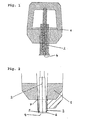
Gemäß Fig. 1 ist ein herkömmlicher Speiser 1 aus einer exothermen und/oder isolierenden Masse über einen Federdorn 2 an dem Gussstück 4 aufgesetzt. Für das Abtrennen bzw. Abschlagen des Speiserrests ist keine optimale Brechkante ausgebildet.1, a
In Fig. 2 ist ein erfindungsgemäßes Speisersystem dargestellt, wobei über den Federdorn 2 ein rohrähnlicher Körper 3 geführt ist, der sich zum Gussstück 4 hin verjüngt. Dadurch wird eine Brechkante 5 ausgebildet. Der rohrähnliche Körper verjüngt sich zum Gussstück hin und sitzt auf dem Fuß bzw. Sockel 6 des Federdorns auf. Auf das Rohr ist ein Speiser(kopf) 1 aufgesetzt, wobei zur Abdichtung zwischen Speiser und Rohrumfang eine Heißklebernaht 7 vorgesehen ist. Nach dem Formen nimmt der Speiser die durch grobe Schraffur gekennzeichnete Stellung ein, wobei die Relativbewegung zwischen rohrähnlichem Körper und Speiser erfolgt und die Positionierung der Brechkante am rohrähnlichen Körper gegenüber dem Gussstück unverändert bleibt. Damit ist eine optimale Positionierung der Brechkante unabhängig von der endgültigen Lage des Speisers nach dem Formen gewährleistet.In Fig. 2, an inventive feeder system is shown, wherein over the
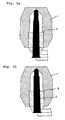
In Fig. 3 ist ein erfindungsgemäßes Speisersystem dargestellt, wobei an der Innenwandung des Speiser(kopf)es 1 ein Vorsprung bzw. ein Anschlag 8 für den rohrähnlichen Körper 3 vorgesehen ist. Der rohrähnliche Körper 3 verjüngt sich zum Gussstück bzw. Formhohlkörper 4 hin und kann sich während des Anformens bzw. der Verdichtung des Formstoffs durch den Formstoff schneiden bzw. zum Gussstück hin vorschieben.In Fig. 3, a feeder system according to the invention is shown, wherein on the inner wall of the feeder (head) 1 there is a projection or a
Wie in der Beschreibung ausgeführt, kann der Federweg bei der Verdichtung des Formstoffs so abgestimmt werden, dass sich die Brechkante am Fuß des Dorns 2 nahe am Gussstück ausbildet. Es ist auch möglich, dass der rohrähnliche Körper keine Verjüngung aufweist und im wesentlich zylindrisch ausgebildet ist.As stated in the description, the spring travel in the compression of the molding material can be adjusted so that the breaking edge forms at the foot of the
In Fig. 3a ist das Speisersystem vor der Verdichtung des Formstoffs dargestellt, wobei das dem Gussstück zugewandte Ende des rohrähnlichen Körpers nicht auf dem Fuß 9des Federdorns aufsitzt bzw. direkt mit dem Gussstück oder dem Formhohlkörper verbunden ist.In Fig. 3a, the feeder system is shown prior to the compression of the molding material, wherein the casting facing the end of the tube-like body is not seated on the
In Fig. 3b ist das Speisersystem nach der Verdichtung des Formstoffs dargestellt, wobei der rohrähnliche Körper direkt mit dem Formhohlkörper verbunden ist bzw. auf dem Fuß 9 des Federdorns 2, falls vorhanden, oder dem Gussstück aufsitzt.In Fig. 3b, the feeder system is shown after the compression of the molding material, wherein the tubular body is directly connected to the hollow body or on the
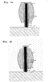
In Figs. 4a und 4b ist eine weitere erfindungsgemäße Ausführungsform dargestellt, wobei der rohrähnliche Körper 3 im vom Gussstück abgewandten Teil Löcher bzw. Öffnungen 10 aufweist. Bei der dargestellten Ausführungsform steht der rohrähnliche Körper bereits vor dem Anformen bzw. Verdichten des Formstoffes am Gussstück 4 auf. Nach dem Anformen bzw. Verdichten des Formstoffes (Fig. 4b) ist der Speiserkopf 1 bewusst im oberen Bereich 1' zerstört worden, wobei eine Relativbewegung zwischen dem rohrähnlichen Körper 3 und dem Speiserkopf 1 erfolgt ist.In Figs. 4a and 4b, another embodiment of the invention is shown, wherein the tube-
Claims (27)
- Feeder system for a casting with a feeder and a tubular body, wherein the tubular body connects the feeder directly or indirectly to the casting, tapers towards the end which faces the casting and has a tapering portion or a contraction of the inside diameter and therefore helps to form a breaking edge.
- Feeder system according to Claim 1, characterised in that the feeder is formed as a feeder head.
- Feeder system according to either of the preceding Claims, characterised in that the tubular body is formed in a cylindrical manner.
- Feeder system according to any one of the preceding Claims, characterised in that a stop or a support for the end of the tubular body which lies opposite the casting is provided in the feeder.
- Feeder system according to any one of the preceding Claims, characterised in that the stop is a projection on the inside of the feeder.
- Feeder system according to any one of the preceding Claims, characterised in that the stop or the support consists of a plurality of support points.
- Feeder system according to any one of the preceding Claims, characterised in that the stop or the support consists of an annular support surface.
- Feeder system according to any one of the preceding Claims, characterised in that the stop or the support is provided at the lateral inner wall of the feeder.
- Feeder system according to any one of the preceding Claims, characterised in that the stop or the support is provided at the upper inner wall of the feeder.
- Feeder system according to any one of the preceding Claims, characterised in that the tubular body is relatively thin-walled, so that it can be cut or advance towards the casting during the start of moulding or compression of the moulding material.
- Feeder system according to any one of the preceding Claims, characterised in that the tubular body can move with respect to the feeder.
- Feeder system according to any one of the preceding Claims, characterised in that a spring mandrel or guide mandrel is also provided, and the tubular body can be at least partly pushed over this.
- Feeder system according to any one of the preceding Claims, characterised in that the tubular body does not stand by way of the side which faces the casting on the spring or guide mandrel before starting to mould or compressing the moulding material.
- Feeder system according to any one of the preceding Claims, characterised in that the tubular body is seated on the base of the spring or guide mandrel at least after starting to mould or compressing the moulding material and a breaking edge is thereby formed near the casting.
- Feeder system according to Claim 12, characterised in that the tubular body replaces the spring or guide mandrel, and a stationary mandrel is optionally provided to centre the tubular body.
- Feeder system according to Claim 15, characterised in that the stationary mandrel is at most as long as the tubular body, and the tubular body is pushed at least partly over the stationary mandrel.
- Feeder system according to Claim 15, characterised in that the stationary mandrel is shorter than the tubular body, and the tubular body is pushed at least partly over the stationary mandrel.
- Use of a tubular body, which tapers towards the end which faces the casting and has a tapering portion or a contraction of the inside diameter, for forming a feeder neck which can be moulded on and has a breaking edge in feeders for castings.
- Casting arrangement, comprising a feeder system according to any one of the preceding Claims, a casting or a moulded hollow body and a moulding material.
- Casting arrangement according to Claim 19, also comprising a spring or guide mandrel.
- Casting arrangement according to Claim 19 or 20, characterised in that the tubular body does not stand by way of the side which faces the casting on the mould before starting to mould or compressing the moulding material.
- Casting arrangement according to any one of Claims 19 to 21, characterised in that the tubular body can move with respect to the casting.
- Method for providing a casting arrangement according to any one of Claims 19 to 22, characterised in that the tubular body is fitted before starting to mould or compressing the moulding material and the feeder is subsequently mounted.
- Method according to Claim 23, characterised in that the tubular body is not directly connected to the casting or the moulded hollow body before starting to mould or compressing the moulding material, but is rather cut up to the casting during compression of the moulding material.
- Method according to Claim 23 or 24, characterised in that the tubular body does not stand on a provided mandrel before starting to mould or compressing the moulding material, but is rather cut up to the casting during compression of the moulding material.
- Method according to Claim 23, characterised in that the tubular body forms a breaking edge on the side which faces the casting, and the feeder does not lie directly on the casting after starting to mould or compressing the moulding material
- Method according to Claim 23, characterised in that the upper part of the feeder is destroyed by the tubular body during the start of moulding or compression of the moulding material.
Applications Claiming Priority (5)
| Application Number | Priority Date | Filing Date | Title |
|---|---|---|---|
| DE2000159481 DE10059481B4 (en) | 2000-11-30 | 2000-11-30 | Feeder with a tube-like body |
| DE10059481 | 2000-11-30 | ||
| DE10142357 | 2001-08-30 | ||
| DE2001142357 DE10142357B4 (en) | 2001-08-30 | 2001-08-30 | Feeder with a tube-like body |
| PCT/EP2001/012730 WO2002043899A2 (en) | 2000-11-30 | 2001-11-02 | Feeder comprising a tubular body |
Publications (3)
| Publication Number | Publication Date |
|---|---|
| EP1345716A2 EP1345716A2 (en) | 2003-09-24 |
| EP1345716B1 true EP1345716B1 (en) | 2007-01-03 |
| EP1345716B2 EP1345716B2 (en) | 2013-07-24 |
Family
ID=26007847
Family Applications (1)
| Application Number | Title | Priority Date | Filing Date |
|---|---|---|---|
| EP01998419.4A Expired - Lifetime EP1345716B2 (en) | 2000-11-30 | 2001-11-02 | Feeder comprising a tubular body |
Country Status (8)
| Country | Link |
|---|---|
| US (2) | US6904952B2 (en) |
| EP (1) | EP1345716B2 (en) |
| JP (2) | JP4379856B2 (en) |
| AT (1) | ATE350181T1 (en) |
| AU (1) | AU2002223665A1 (en) |
| DE (2) | DE20115140U1 (en) |
| ES (1) | ES2280436T5 (en) |
| WO (1) | WO2002043899A2 (en) |
Cited By (3)
| Publication number | Priority date | Publication date | Assignee | Title |
|---|---|---|---|---|
| EP3819042A1 (en) | 2019-11-06 | 2021-05-12 | GTP Schäfer Gießtechnische Produkte GmbH | Feeder insert with resilient metal foot |
| DE202019005681U1 (en) | 2019-11-06 | 2021-06-16 | GTP Schäfer Gießtechnische Produkte GmbH | Feeder insert with springy metal base |
| DE202022105722U1 (en) | 2022-10-11 | 2022-11-04 | Ask Chemicals Gmbh | Feeder with moveable spout |
Families Citing this family (22)
| Publication number | Priority date | Publication date | Assignee | Title |
|---|---|---|---|---|
| DE20115140U1 (en) * | 2000-11-30 | 2002-01-31 | Luengen Gmbh & Co Kg As | Feeder with a tubular body |
| GB0325134D0 (en) | 2003-10-28 | 2003-12-03 | Foseco Int | Improved feeder element for metal casting |
| ATE435082T1 (en) * | 2004-03-31 | 2009-07-15 | Luengen Gmbh As | FEEDER WITH MOLDABLE SPOUT |
| DE102004017062A1 (en) * | 2004-04-02 | 2005-10-20 | Luengen Gmbh & Co Kg As | Umbrella or dowel feeder |
| DE102005008324A1 (en) * | 2005-02-23 | 2006-08-24 | AS Lüngen GmbH & Co. KG | Cast metal feeder having feeder head having hollow space with at least one hole open to environment and tube-shaped body used in metal casting operations has element for preventing tube-shaped body from falling out |
| DE102005011644A1 (en) * | 2005-03-14 | 2006-09-21 | AS Lüngen GmbH & Co. KG | Exothermic and insulating feeder inserts with high gas permeability |
| DE102005025701B4 (en) * | 2005-06-04 | 2007-03-08 | GTP Schäfer Gießtechnische Produkte GmbH | Feeder with yielding feeder base |
| DE102006025441A1 (en) * | 2006-05-31 | 2007-12-06 | Süd-Chemie AG | Test device for tube bundle reactors |
| JP5031700B2 (en) * | 2008-09-09 | 2012-09-19 | 有限会社フオセコ・ジャパン・リミテッド | Sand mold manufacturing method and jig |
| PL2489450T3 (en) * | 2011-02-17 | 2014-12-31 | Foseco Int | Feeder element |
| ES2669183T3 (en) | 2013-02-15 | 2018-05-24 | Chemex Gmbh | Insert of feeding device and procedure for its arrangement in a foundry mold |
| DE102013209775B3 (en) * | 2013-05-27 | 2014-10-23 | Chemex Gmbh | feeder sleeve |
| EP2815819B1 (en) * | 2013-06-21 | 2017-07-05 | LMA Motif Al. Döküm San. Müm. Ltd. Sti. | Exothermic feeder |
| DE202013104863U1 (en) | 2013-10-30 | 2013-11-15 | GTP Schäfer Gießtechnische Produkte GmbH | Feeder insert with a stopper arranged in its lid area |
| GB201415516D0 (en) | 2014-09-02 | 2014-10-15 | Foseco Int | Feeder system |
| CN105522115B (en) * | 2014-09-30 | 2017-12-19 | 济南圣泉倍进陶瓷过滤器有限公司 | Feeding device and system and high pressure moulding method |
| ES2781584T3 (en) | 2015-09-02 | 2020-09-03 | Foseco Int | Feeding system |
| TR201510862B (en) | 2015-09-02 | 2018-08-27 | Foseco Int | FEEDING ELEMENT |
| EP3334547A1 (en) | 2015-09-02 | 2018-06-20 | Foseco International Limited | Feeder system |
| DE102015120866A1 (en) * | 2015-12-01 | 2017-06-01 | HÜTTENES-ALBERTUS Chemische Werke Gesellschaft mit beschränkter Haftung | Process for producing refractory composite particles and feeder elements for the foundry industry, corresponding feeder elements and uses |
| DE102017131280A1 (en) * | 2017-12-22 | 2019-06-27 | Chemex Foundry Solutions Gmbh | A method of manufacturing a molded article and a feeder insert for use in such a method |
| CN110744030B (en) * | 2019-11-05 | 2021-10-19 | 杭州杭富锅炉成套设备有限公司 | Method for manufacturing small radius of boiler pipeline |
Family Cites Families (20)
| Publication number | Priority date | Publication date | Assignee | Title |
|---|---|---|---|---|
| JPS4328011Y1 (en) * | 1965-01-22 | 1968-11-19 | ||
| JPS5220414B1 (en) * | 1969-01-28 | 1977-06-03 | ||
| US4025047A (en) * | 1974-04-11 | 1977-05-24 | Aikoh Co., Ltd. | Moulding for the heat retention of feeder head in casting molten metals |
| GB1464720A (en) * | 1974-12-03 | 1977-02-16 | ||
| GB1597832A (en) * | 1977-03-01 | 1981-09-09 | Foseco Trading Ag | Breaker core assembly for use in the casting of molten metals |
| DE3122597A1 (en) † | 1981-06-06 | 1982-12-23 | Mannesmann Rexroth GmbH, 8770 Lohr | "FOOD FOR A CAST PIECE" |
| GB8400970D0 (en) * | 1984-01-13 | 1984-02-15 | Foseco Int | Metal casting moulds |
| US4526338A (en) | 1984-04-23 | 1985-07-02 | General Foundry Products Corporation | High pressure molding riser |
| DE3614629A1 (en) * | 1986-04-30 | 1987-11-05 | Grohe Armaturen Friedrich | Casting device |
| DE4200183A1 (en) | 1991-01-14 | 1992-07-16 | Erich Kuehn | Two=part feeder esp. for iron castings - comprising bottom part of exothermic material with elongated oval feed opening and fitting hollow top part forming cavity |
| DE4119192A1 (en) | 1991-06-11 | 1992-12-17 | Hoesch Ag | Spring-supported feeder material for sand moulds - with spring area protected from sand and dust particles by a jar-shaped cover |
| JPH08103850A (en) * | 1994-09-30 | 1996-04-23 | Kurimoto Ltd | Feeder head neck down core for casting |
| DE19503456C1 (en) * | 1995-02-03 | 1995-11-02 | Daimler Benz Ag | Arrangement consisting of a pot=shaped feeder supported by a mandrel on a casting pattern |
| DE19642838A1 (en) | 1996-10-17 | 1997-07-31 | Daimler Benz Ag | Feeder for metal casting comprising exothermic material with flat ring set on one end |
| DE19925167A1 (en) | 1999-06-01 | 2000-12-14 | Luengen Gmbh & Co Kg As | Exothermic feeder mass |
| GB0003857D0 (en) * | 2000-02-19 | 2000-04-05 | Gough Michael J | Refractory compositions |
| DE10039519B4 (en) * | 2000-08-08 | 2007-05-31 | Chemex Gmbh | feeder sleeve |
| DE20115140U1 (en) * | 2000-11-30 | 2002-01-31 | Luengen Gmbh & Co Kg As | Feeder with a tubular body |
| DE10059481B4 (en) | 2000-11-30 | 2012-02-23 | AS Lüngen GmbH | Feeder with a tube-like body |
| DE20112425U1 (en) * | 2001-07-27 | 2001-10-18 | Gtp Schaefer Giestechnische Pr | Feeder insert with metallic feeder foot |
-
2001
- 2001-09-13 DE DE20115140U patent/DE20115140U1/en not_active Expired - Lifetime
- 2001-11-02 JP JP2002545862A patent/JP4379856B2/en not_active Expired - Fee Related
- 2001-11-02 US US10/433,236 patent/US6904952B2/en not_active Expired - Lifetime
- 2001-11-02 DE DE50111827T patent/DE50111827D1/en not_active Expired - Lifetime
- 2001-11-02 AT AT01998419T patent/ATE350181T1/en not_active IP Right Cessation
- 2001-11-02 ES ES01998419T patent/ES2280436T5/en not_active Expired - Lifetime
- 2001-11-02 AU AU2002223665A patent/AU2002223665A1/en not_active Abandoned
- 2001-11-02 EP EP01998419.4A patent/EP1345716B2/en not_active Expired - Lifetime
- 2001-11-02 WO PCT/EP2001/012730 patent/WO2002043899A2/en active IP Right Grant
-
2005
- 2005-06-06 US US11/145,798 patent/US7320355B2/en not_active Expired - Lifetime
-
2008
- 2008-10-14 JP JP2008265811A patent/JP2009006401A/en active Pending
Cited By (4)
| Publication number | Priority date | Publication date | Assignee | Title |
|---|---|---|---|---|
| EP3819042A1 (en) | 2019-11-06 | 2021-05-12 | GTP Schäfer Gießtechnische Produkte GmbH | Feeder insert with resilient metal foot |
| DE202019005681U1 (en) | 2019-11-06 | 2021-06-16 | GTP Schäfer Gießtechnische Produkte GmbH | Feeder insert with springy metal base |
| DE202022105722U1 (en) | 2022-10-11 | 2022-11-04 | Ask Chemicals Gmbh | Feeder with moveable spout |
| WO2024079189A1 (en) | 2022-10-11 | 2024-04-18 | Ask Chemicals Gmbh | Riser with a movable spout |
Also Published As
| Publication number | Publication date |
|---|---|
| DE50111827D1 (en) | 2007-02-15 |
| WO2002043899A2 (en) | 2002-06-06 |
| ES2280436T5 (en) | 2013-12-13 |
| ES2280436T3 (en) | 2007-09-16 |
| JP2004532737A (en) | 2004-10-28 |
| JP4379856B2 (en) | 2009-12-09 |
| EP1345716B2 (en) | 2013-07-24 |
| ATE350181T1 (en) | 2007-01-15 |
| US20040050526A1 (en) | 2004-03-18 |
| DE20115140U1 (en) | 2002-01-31 |
| US7320355B2 (en) | 2008-01-22 |
| US20060000574A1 (en) | 2006-01-05 |
| US6904952B2 (en) | 2005-06-14 |
| JP2009006401A (en) | 2009-01-15 |
| AU2002223665A1 (en) | 2002-06-11 |
| EP1345716A2 (en) | 2003-09-24 |
| WO2002043899A3 (en) | 2002-09-26 |
Similar Documents
| Publication | Publication Date | Title |
|---|---|---|
| EP1345716B1 (en) | Feeder comprising a tubular body | |
| EP1850987B1 (en) | Feeder comprising a mobile socket | |
| EP1184104B1 (en) | Feeder insert | |
| EP2097193B1 (en) | Feeder insert and feeder element | |
| EP2899003B1 (en) | Die cast mould for producing a casting and a method for manufacturing a unitary toilet bowl | |
| EP1732719B1 (en) | Feeder provided with a deformable socket | |
| EP3003601B2 (en) | Feeder sleeve, forming element for the feeder sleeve and method for casting metal using the same | |
| DE102005019385A1 (en) | Foundry casting funnel feeding molten metal into mold, includes supported ceramic filter insert near top opening above feeder chamber | |
| DE102015101913B3 (en) | Injector with integrated loose filter, casting system consisting of the insert feeder and a mold model and method for producing a casting mold | |
| EP2982458B1 (en) | Assembly for use in the manufacture of a divisible mould | |
| DE10142357B4 (en) | Feeder with a tube-like body | |
| EP3727723A1 (en) | Method for producing a moulded part and feeder insert for use in such a method | |
| EP0779844A1 (en) | Feeder for use in casting molten metal | |
| DE10059481B4 (en) | Feeder with a tube-like body | |
| WO2020169462A1 (en) | One-piece feeder body for use while casting metals | |
| EP1779944B1 (en) | Feeder head with plug for closing its entry | |
| DE102010022834B4 (en) | Spring thorn and casting model with spring thorn | |
| EP3368234B1 (en) | Pin having an expandable casing, and casting model having a pin, and method for casting metals | |
| DE202016103215U1 (en) | Modular feeder system | |
| DE102015101912A1 (en) | Injection feeder with integrated loose filter, casting system consisting of the sprue feeder and a mold model and method for producing a casting mold and casting method using this casting system | |
| DE102017119443B3 (en) | Infeed feeder with integrated filter | |
| DE102004007094B3 (en) | Process for production of a cast metal housing for a streaming fluid with a tube section, and connecting flange with a sealing surface useful in production of pump housings for streaming fluids | |
| DE202023100381U1 (en) | Feeder with lid | |
| WO2022180103A1 (en) | Vertically divided feeder for being used when pouring metals into casting moulds, and method for the production thereof | |
| WO1999008291A1 (en) | Ventilation valve |
Legal Events
| Date | Code | Title | Description |
|---|---|---|---|
| PUAI | Public reference made under article 153(3) epc to a published international application that has entered the european phase |
Free format text: ORIGINAL CODE: 0009012 |
|
| 17P | Request for examination filed |
Effective date: 20030519 |
|
| AK | Designated contracting states |
Kind code of ref document: A2 Designated state(s): AT BE CH CY DE DK ES FI FR GB GR IE IT LI LU MC NL PT SE TR |
|
| AX | Request for extension of the european patent |
Extension state: AL LT LV MK RO SI |
|
| 17Q | First examination report despatched |
Effective date: 20041019 |
|
| GRAP | Despatch of communication of intention to grant a patent |
Free format text: ORIGINAL CODE: EPIDOSNIGR1 |
|
| GRAS | Grant fee paid |
Free format text: ORIGINAL CODE: EPIDOSNIGR3 |
|
| GRAA | (expected) grant |
Free format text: ORIGINAL CODE: 0009210 |
|
| AK | Designated contracting states |
Kind code of ref document: B1 Designated state(s): AT BE CH CY DE DK ES FI FR GB GR IE IT LI LU MC NL PT SE TR |
|
| PG25 | Lapsed in a contracting state [announced via postgrant information from national office to epo] |
Ref country code: IE Free format text: LAPSE BECAUSE OF FAILURE TO SUBMIT A TRANSLATION OF THE DESCRIPTION OR TO PAY THE FEE WITHIN THE PRESCRIBED TIME-LIMIT Effective date: 20070103 Ref country code: DK Free format text: LAPSE BECAUSE OF FAILURE TO SUBMIT A TRANSLATION OF THE DESCRIPTION OR TO PAY THE FEE WITHIN THE PRESCRIBED TIME-LIMIT Effective date: 20070103 Ref country code: NL Free format text: LAPSE BECAUSE OF FAILURE TO SUBMIT A TRANSLATION OF THE DESCRIPTION OR TO PAY THE FEE WITHIN THE PRESCRIBED TIME-LIMIT Effective date: 20070103 Ref country code: FI Free format text: LAPSE BECAUSE OF FAILURE TO SUBMIT A TRANSLATION OF THE DESCRIPTION OR TO PAY THE FEE WITHIN THE PRESCRIBED TIME-LIMIT Effective date: 20070103 |
|
| REG | Reference to a national code |
Ref country code: GB Ref legal event code: FG4D Free format text: NOT ENGLISH |
|
| REF | Corresponds to: |
Ref document number: 50111827 Country of ref document: DE Date of ref document: 20070215 Kind code of ref document: P |
|
| REG | Reference to a national code |
Ref country code: IE Ref legal event code: FG4D Free format text: LANGUAGE OF EP DOCUMENT: GERMAN |
|
| PG25 | Lapsed in a contracting state [announced via postgrant information from national office to epo] |
Ref country code: SE Free format text: LAPSE BECAUSE OF FAILURE TO SUBMIT A TRANSLATION OF THE DESCRIPTION OR TO PAY THE FEE WITHIN THE PRESCRIBED TIME-LIMIT Effective date: 20070403 |
|
| GBT | Gb: translation of ep patent filed (gb section 77(6)(a)/1977) |
Effective date: 20070411 |
|
| PG25 | Lapsed in a contracting state [announced via postgrant information from national office to epo] |
Ref country code: PT Free format text: LAPSE BECAUSE OF FAILURE TO SUBMIT A TRANSLATION OF THE DESCRIPTION OR TO PAY THE FEE WITHIN THE PRESCRIBED TIME-LIMIT Effective date: 20070604 |
|
| NLV1 | Nl: lapsed or annulled due to failure to fulfill the requirements of art. 29p and 29m of the patents act | ||
| ET | Fr: translation filed | ||
| REG | Reference to a national code |
Ref country code: ES Ref legal event code: FG2A Ref document number: 2280436 Country of ref document: ES Kind code of ref document: T3 |
|
| REG | Reference to a national code |
Ref country code: IE Ref legal event code: FD4D |
|
| PLBI | Opposition filed |
Free format text: ORIGINAL CODE: 0009260 |
|
| 26 | Opposition filed |
Opponent name: GTP SCHAEFER GIESSTECHNISCHE PRODUKTE GMBH Effective date: 20071002 |
|
| PLAX | Notice of opposition and request to file observation + time limit sent |
Free format text: ORIGINAL CODE: EPIDOSNOBS2 |
|
| PLAF | Information modified related to communication of a notice of opposition and request to file observations + time limit |
Free format text: ORIGINAL CODE: EPIDOSCOBS2 |
|
| PG25 | Lapsed in a contracting state [announced via postgrant information from national office to epo] |
Ref country code: GR Free format text: LAPSE BECAUSE OF FAILURE TO SUBMIT A TRANSLATION OF THE DESCRIPTION OR TO PAY THE FEE WITHIN THE PRESCRIBED TIME-LIMIT Effective date: 20070404 |
|
| BERE | Be: lapsed |
Owner name: AS LUNGEN G.M.B.H. & CO. KG Effective date: 20071130 |
|
| PLBB | Reply of patent proprietor to notice(s) of opposition received |
Free format text: ORIGINAL CODE: EPIDOSNOBS3 |
|
| PG25 | Lapsed in a contracting state [announced via postgrant information from national office to epo] |
Ref country code: MC Free format text: LAPSE BECAUSE OF NON-PAYMENT OF DUE FEES Effective date: 20071130 |
|
| PG25 | Lapsed in a contracting state [announced via postgrant information from national office to epo] |
Ref country code: LI Free format text: LAPSE BECAUSE OF NON-PAYMENT OF DUE FEES Effective date: 20071130 Ref country code: CH Free format text: LAPSE BECAUSE OF NON-PAYMENT OF DUE FEES Effective date: 20071130 |
|
| REG | Reference to a national code |
Ref country code: CH Ref legal event code: PL |
|
| PLAB | Opposition data, opponent's data or that of the opponent's representative modified |
Free format text: ORIGINAL CODE: 0009299OPPO |
|
| PG25 | Lapsed in a contracting state [announced via postgrant information from national office to epo] |
Ref country code: BE Free format text: LAPSE BECAUSE OF NON-PAYMENT OF DUE FEES Effective date: 20071130 |
|
| PLAY | Examination report in opposition despatched + time limit |
Free format text: ORIGINAL CODE: EPIDOSNORE2 |
|
| PG25 | Lapsed in a contracting state [announced via postgrant information from national office to epo] |
Ref country code: AT Free format text: LAPSE BECAUSE OF NON-PAYMENT OF DUE FEES Effective date: 20071102 |
|
| PLAH | Information related to despatch of examination report in opposition + time limit modified |
Free format text: ORIGINAL CODE: EPIDOSCORE2 |
|
| PLBC | Reply to examination report in opposition received |
Free format text: ORIGINAL CODE: EPIDOSNORE3 |
|
| PG25 | Lapsed in a contracting state [announced via postgrant information from national office to epo] |
Ref country code: CY Free format text: LAPSE BECAUSE OF FAILURE TO SUBMIT A TRANSLATION OF THE DESCRIPTION OR TO PAY THE FEE WITHIN THE PRESCRIBED TIME-LIMIT Effective date: 20070103 |
|
| PG25 | Lapsed in a contracting state [announced via postgrant information from national office to epo] |
Ref country code: LU Free format text: LAPSE BECAUSE OF NON-PAYMENT OF DUE FEES Effective date: 20071102 |
|
| PG25 | Lapsed in a contracting state [announced via postgrant information from national office to epo] |
Ref country code: TR Free format text: LAPSE BECAUSE OF FAILURE TO SUBMIT A TRANSLATION OF THE DESCRIPTION OR TO PAY THE FEE WITHIN THE PRESCRIBED TIME-LIMIT Effective date: 20070103 |
|
| RAP2 | Party data changed (patent owner data changed or rights of a patent transferred) |
Owner name: AS LUENGEN GMBH |
|
| PLCK | Communication despatched that opposition was rejected |
Free format text: ORIGINAL CODE: EPIDOSNREJ1 |
|
| APBM | Appeal reference recorded |
Free format text: ORIGINAL CODE: EPIDOSNREFNO |
|
| APBP | Date of receipt of notice of appeal recorded |
Free format text: ORIGINAL CODE: EPIDOSNNOA2O |
|
| APAH | Appeal reference modified |
Free format text: ORIGINAL CODE: EPIDOSCREFNO |
|
| APBQ | Date of receipt of statement of grounds of appeal recorded |
Free format text: ORIGINAL CODE: EPIDOSNNOA3O |
|
| REG | Reference to a national code |
Ref country code: DE Ref legal event code: R082 Ref document number: 50111827 Country of ref document: DE Representative=s name: MUELLER SCHUPFNER & PARTNER PATENT- UND RECHTS, DE |
|
| REG | Reference to a national code |
Ref country code: DE Ref legal event code: R082 Ref document number: 50111827 Country of ref document: DE Representative=s name: MUELLER SCHUPFNER & PARTNER PATENT- UND RECHTS, DE Effective date: 20120119 Ref country code: DE Ref legal event code: R081 Ref document number: 50111827 Country of ref document: DE Owner name: ASK CHEMICALS FEEDING SYSTEMS GMBH, DE Free format text: FORMER OWNER: AS LUENGEN GMBH, 56170 BENDORF, DE Effective date: 20120119 |
|
| APBU | Appeal procedure closed |
Free format text: ORIGINAL CODE: EPIDOSNNOA9O |
|
| RAP2 | Party data changed (patent owner data changed or rights of a patent transferred) |
Owner name: ASK CHEMICALS FEEDING SYSTEMS GMBH |
|
| PLAO | Information deleted related to despatch of communication that opposition is rejected |
Free format text: ORIGINAL CODE: EPIDOSDREJ1 |
|
| PUAH | Patent maintained in amended form |
Free format text: ORIGINAL CODE: 0009272 |
|
| STAA | Information on the status of an ep patent application or granted ep patent |
Free format text: STATUS: PATENT MAINTAINED AS AMENDED |
|
| 27A | Patent maintained in amended form |
Effective date: 20130724 |
|
| AK | Designated contracting states |
Kind code of ref document: B2 Designated state(s): AT BE CH CY DE DK ES FI FR GB GR IE IT LI LU MC NL PT SE TR |
|
| REG | Reference to a national code |
Ref country code: DE Ref legal event code: R102 Ref document number: 50111827 Country of ref document: DE Effective date: 20130724 |
|
| REG | Reference to a national code |
Ref country code: ES Ref legal event code: DC2A Ref document number: 2280436 Country of ref document: ES Kind code of ref document: T5 Effective date: 20131213 |
|
| REG | Reference to a national code |
Ref country code: FR Ref legal event code: PLFP Year of fee payment: 15 |
|
| REG | Reference to a national code |
Ref country code: FR Ref legal event code: PLFP Year of fee payment: 16 |
|
| REG | Reference to a national code |
Ref country code: FR Ref legal event code: PLFP Year of fee payment: 17 |
|
| PGFP | Annual fee paid to national office [announced via postgrant information from national office to epo] |
Ref country code: FR Payment date: 20171124 Year of fee payment: 17 |
|
| PG25 | Lapsed in a contracting state [announced via postgrant information from national office to epo] |
Ref country code: FR Free format text: LAPSE BECAUSE OF NON-PAYMENT OF DUE FEES Effective date: 20181130 |
|
| PGFP | Annual fee paid to national office [announced via postgrant information from national office to epo] |
Ref country code: GB Payment date: 20201123 Year of fee payment: 20 Ref country code: ES Payment date: 20201214 Year of fee payment: 20 Ref country code: IT Payment date: 20201130 Year of fee payment: 20 |
|
| PGFP | Annual fee paid to national office [announced via postgrant information from national office to epo] |
Ref country code: DE Payment date: 20210126 Year of fee payment: 20 |
|
| REG | Reference to a national code |
Ref country code: DE Ref legal event code: R071 Ref document number: 50111827 Country of ref document: DE |
|
| REG | Reference to a national code |
Ref country code: GB Ref legal event code: PE20 Expiry date: 20211101 |
|
| PG25 | Lapsed in a contracting state [announced via postgrant information from national office to epo] |
Ref country code: GB Free format text: LAPSE BECAUSE OF EXPIRATION OF PROTECTION Effective date: 20211101 |
|
| REG | Reference to a national code |
Ref country code: ES Ref legal event code: FD2A Effective date: 20220225 |
|
| PG25 | Lapsed in a contracting state [announced via postgrant information from national office to epo] |
Ref country code: ES Free format text: LAPSE BECAUSE OF EXPIRATION OF PROTECTION Effective date: 20211103 |