EP1342917B1 - Pumpeinrichtung für aggressive Flüssigkeiten - Google Patents
Pumpeinrichtung für aggressive Flüssigkeiten Download PDFInfo
- Publication number
- EP1342917B1 EP1342917B1 EP03010547A EP03010547A EP1342917B1 EP 1342917 B1 EP1342917 B1 EP 1342917B1 EP 03010547 A EP03010547 A EP 03010547A EP 03010547 A EP03010547 A EP 03010547A EP 1342917 B1 EP1342917 B1 EP 1342917B1
- Authority
- EP
- European Patent Office
- Prior art keywords
- pump
- valve
- piston
- bore
- piston pumps
- Prior art date
- Legal status (The legal status is an assumption and is not a legal conclusion. Google has not performed a legal analysis and makes no representation as to the accuracy of the status listed.)
- Expired - Lifetime
Links
- 239000007788 liquid Substances 0.000 title claims description 10
- 229910001338 liquidmetal Inorganic materials 0.000 claims description 4
- 229910052782 aluminium Inorganic materials 0.000 claims description 3
- XAGFODPZIPBFFR-UHFFFAOYSA-N aluminium Chemical compound [Al] XAGFODPZIPBFFR-UHFFFAOYSA-N 0.000 claims description 3
- 239000004411 aluminium Substances 0.000 claims 1
- 238000005086 pumping Methods 0.000 description 11
- 238000005266 casting Methods 0.000 description 6
- 229910010293 ceramic material Inorganic materials 0.000 description 2
- NHWNVPNZGGXQQV-UHFFFAOYSA-J [Si+4].[O-]N=O.[O-]N=O.[O-]N=O.[O-]N=O Chemical compound [Si+4].[O-]N=O.[O-]N=O.[O-]N=O.[O-]N=O NHWNVPNZGGXQQV-UHFFFAOYSA-J 0.000 description 1
- 239000000919 ceramic Substances 0.000 description 1
- 239000012467 final product Substances 0.000 description 1
- 239000012530 fluid Substances 0.000 description 1
- 239000000155 melt Substances 0.000 description 1
- 238000005457 optimization Methods 0.000 description 1
- 230000003647 oxidation Effects 0.000 description 1
- 238000007254 oxidation reaction Methods 0.000 description 1
- 239000002689 soil Substances 0.000 description 1
Images



Classifications
-
- F—MECHANICAL ENGINEERING; LIGHTING; HEATING; WEAPONS; BLASTING
- F04—POSITIVE - DISPLACEMENT MACHINES FOR LIQUIDS; PUMPS FOR LIQUIDS OR ELASTIC FLUIDS
- F04B—POSITIVE-DISPLACEMENT MACHINES FOR LIQUIDS; PUMPS
- F04B7/00—Piston machines or pumps characterised by having positively-driven valving
- F04B7/0038—Piston machines or pumps characterised by having positively-driven valving the distribution member forming a single inlet for a plurality of pumping chambers or a multiple discharge for one single pumping chamber
-
- F—MECHANICAL ENGINEERING; LIGHTING; HEATING; WEAPONS; BLASTING
- F04—POSITIVE - DISPLACEMENT MACHINES FOR LIQUIDS; PUMPS FOR LIQUIDS OR ELASTIC FLUIDS
- F04B—POSITIVE-DISPLACEMENT MACHINES FOR LIQUIDS; PUMPS
- F04B15/00—Pumps adapted to handle specific fluids, e.g. by selection of specific materials for pumps or pump parts
- F04B15/04—Pumps adapted to handle specific fluids, e.g. by selection of specific materials for pumps or pump parts the fluids being hot or corrosive
-
- F—MECHANICAL ENGINEERING; LIGHTING; HEATING; WEAPONS; BLASTING
- F04—POSITIVE - DISPLACEMENT MACHINES FOR LIQUIDS; PUMPS FOR LIQUIDS OR ELASTIC FLUIDS
- F04B—POSITIVE-DISPLACEMENT MACHINES FOR LIQUIDS; PUMPS
- F04B53/00—Component parts, details or accessories not provided for in, or of interest apart from, groups F04B1/00 - F04B23/00 or F04B39/00 - F04B47/00
- F04B53/16—Casings; Cylinders; Cylinder liners or heads; Fluid connections
Definitions
- the invention relates to a pumping device for aggressive liquids, especially liquid metals, eg. As lead or aluminum with several Piston dosing pumps and a pump housing with a Pump bottom, wherein the pump bottom has at least one valve, this in conjunction with several channels arranged in the bottom of the pump stands, wherein the pump bottom has a plurality of disc-like segments, wherein the individual segments to form the channels with each other connected grooves and bores, wherein the piston metering pumps are connected by a common pressure tube.
- liquid metals eg. As lead or aluminum with several Piston dosing pumps
- the pump bottom has at least one valve, this in conjunction with several channels arranged in the bottom of the pump stands, wherein the pump bottom has a plurality of disc-like segments, wherein the individual segments to form the channels with each other connected grooves and bores, wherein the piston metering pumps are connected by a common pressure tube.
- the invention is therefore based on the object, a pumping device of educate the aforementioned type such that hereby an exactly metered delivery of the liquid can be done.
- Another advantage of the separate drive for each pump is in that hereby also the promotion can be made uniform.
- the piston metering pumps of the pumping device a common housing, wherein the housing has a common Pressure channel for the piston metering pumps has. That is, at two parallel piston metering pumps in a pumping device, the piston metering pumps each a separate feed for the pumped Having casting medium, but a single output for the subsidized Medium. In particular, this is the continuous promotion of the Casting medium ensured in the mold.
- the piston pump designated overall by 1 shows the cylinder 2 and arranged in the cylinder designated 3 Piston.
- the bottom of the cylinder is generally designated 10.
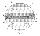
- the floor 10 consists of the three disc-shaped segments 20, 30 and 40, the are interconnected by screws 70, as this is for example, from Figure 2 results.
- the disk-shaped segment 20 has a bore 21, with which the Pump bottom is in communication with the interior of the cylinder 2. Of Further, the segment 20 has a bore 22 which in the 25, 35 designated valve chamber opens. The valve chamber 25, 35 has in the region of Output of the bore 22, the valve seat 23.
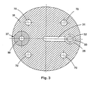
- the disc-shaped segment 30th shows a horizontally extending groove 31 which fits to the bore 21 of disc-shaped segment 20 connects, and also in the valve chamber 25, 35 opens. At the valve chamber 25, 35 closes down again a bore 32, which has the valve seat 33. Close to the bore 32 a turn horizontally extending groove 41 in the disk-shaped Segment 40, which terminates in the pressure tube designated 50.
- This Pressure tube 50 is T-shaped in its arranged at the pump bottom end (at 55), whereby it in the region of the segments 20 and 30 by a corresponding recess 37 in the segment 30 and 27 in the segment 20 is received positively.
- the pressure tube 50 can be heated designed to melt without lowering the temperature in the mold to be able to bring.
- valve In the region of the valve space 25, 35 is the valve designated 60 with the valve body 61 and the valve rod 62.
- the valve body 61 cooperates with the valve seats 23 and 33 together.
- the piston metering pump can be used as a submersible pump, with the inlet taking place through the annular gap between the bore 22 and the valve rod 62 into the valve housing 25, 35.
- the bore 32 In the case of the inlet, the bore 32 is shut off by the valve body 61 through the valve body 61.
- D. h. The liquid passes through the bore 22, the channel 31 and the bore 21 into the cylinder 2. With a corresponding downward movement of the piston 3, the liquid is when the valve body rests against the upper valve seat 23, through the bore 21st , the channel 31, the bore 32 and the channel 41 passed into the pressure tube 50.
- the disc-shaped segments 20, 30, 40 and also the pressure tube 50 are preferably made of a ceramic or according to coated to counteract the wear by the liquid metal.
- FIG. 5 In the illustration according to FIG. 5 and according to the sections according to FIG Figures 6 to 8 is a pumping device with two piston metering pumps shown.
- the arrangement of the two piston metering pumps 1 in the Pumping device is parallel, but each one designated 1 Piston pump a separate drive (not shown) shows.
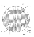
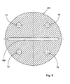
- a piston metering pump according to the figures 1 to 4 referred only to the Bottom of the pumping device with the two piston metering pumps something is different the pump bottom 100 of the pumping device consists from the six segments 110, 120, 130, 140, 150 and 160. Again, the disc-shaped segments 110 to 160 held by screws 70, such as this results from the sectional views according to FIGS. 6 to 8.
- the disc-shaped segment 110 has two holes 111, with the Pump bottom with the respective interior of the cylinder 2 in conjunction stands. Furthermore, the segment 110 has two holes 112, which in the With 135 designated valve chamber open. The valve space 135 points in the area the output of the bore 112, the valve seat 123.
- the disc-shaped Segment 130 has a horizontally extending groove 131 which in conjunction with the bore 111 is. In the area of the disk-shaped segment 140 In turn, there is a respective hole 141 with a corresponding Valve seat 142.
- a valve 180th provided with the valve body 181 and the valve rod 182nd Der Valve body works with the respective valve seats 123, 142 together.
- the disk-shaped segment 150 shows a long groove 190, which is finally in communication with the pressure tube 50. Finally, the disc-shaped segment 160 forms the conclusion of the Soil 100.
- the operation of this pumping device is essentially equal to that of Figure 1 - 4, so that in detail not discussed must become.
Landscapes
- Engineering & Computer Science (AREA)
- Mechanical Engineering (AREA)
- General Engineering & Computer Science (AREA)
- Reciprocating Pumps (AREA)
- Details Of Reciprocating Pumps (AREA)
Description
- Figur 1
- zeigt eine Kolben-Dosierpumpe in einer Seitenansicht schematisch im Schnitt;
- Figur 2
- zeigt einen Schnitt gemäß der Linie II/II aus Figur 1;
- Figur 3
- zeigt einen Schnitt gemäß der Linie III/III aus Figur 1;
- Figur 4
- zeigt einen Schnitt gemäß der Linie IV/IV aus Figur 1:
- Figur 5
- zeigt eine parallele Anordnung zweier Kolben-Dosierpumpen in einem gemeinsamen Gehäuse als Pumpeinrichtung im Schnitt;
- Figuren 6-8
- zeigen Schnitte des Bodens gemäß der Pumpeinrichtung aus Figur 5
Die Kolben-Dosierpumpe ist als Tauchpumpe einsetzbar, wobei der Einlass durch den ringförmigen Spalt zwischen der Bohrung 22 und der Ventilstange 62 in das Ventilgehäuse 25, 35 stattfindet. Im Falle des Einlasses wird durch den Ventilkörper 61 die Bohrung 32 durch den Ventilkörper 61 abgesperrt. D. h., die Flüssigkeit gelangt durch die Bohrung 22, den Kanal 31 und die Bohrung 21 in den Zylinder 2. Bei entsprechender Abwärtsbewegung des Kolbens 3 wird die Flüssigkeit dann, wenn der Ventilkörper an dem oberen Ventilsitz 23 anliegt, durch die Bohrung 21, den Kanal 31, die Bohrung 32 und den Kanal 41 in das Druckrohr 50 geleitet.
Claims (3)
- Pumpeinrichtung für aggressive Flüssigkeiten, insbesondere flüssige Metalle, z. B. Blei oder Aluminium, mit mehreren Kolben-Dosierpumpen und einem Pumpengehäuse mit einem Pumpenboden (10), wobei der Pumpenboden (10) mindestens ein Ventil (60) aufweist, das mit mehreren im Pumpenboden angeordneten Kanälen in Verbindung steht, wobei der Pumpenboden (10) mehrere scheibenartige Segmente (20, 30, 40) aufweist, wobei die einzelnen Segmente (20, 30, 40) zur Bildung der Kanäle untereinander verbundene Nuten und Bohrungen (21, 22, 31, 41) aufweisen, wobei die Kolben-Dosierpumpen durch ein gemeinsames Druckrohr verbunden sind,
dadurch gekennzeichnet, dass jede Kolben-Dosierpumpe (1) einen gesonderten Antrieb aufweist. - Pumpeinrichtung nach Anspruch 1,
dadurch gekennzeichnet dass die Kolben-Dosierpumpen (1) parallel zueinander angeordnet sind. - Pumpeinrichtung nach Anspruch 1,
dadurch gekennzeichnet, dass die Kolben-Dosierpumpen (1) der Pumpeinrichtung ein gemeinsames Gehäuse aufweisen.
Applications Claiming Priority (5)
| Application Number | Priority Date | Filing Date | Title |
|---|---|---|---|
| DE29906403U | 1999-04-10 | ||
| DE29906403 | 1999-04-10 | ||
| DE20001099U | 2000-01-22 | ||
| DE20001099U DE20001099U1 (de) | 1999-04-10 | 2000-01-22 | Kolbendosierpumpe für aggressive Flüssigkeiten |
| EP00926706A EP1171709B1 (de) | 1999-04-10 | 2000-04-10 | Kolben-dosierpumpe für aggressive flüssigkeiten |
Related Parent Applications (2)
| Application Number | Title | Priority Date | Filing Date |
|---|---|---|---|
| EP00926706A Division EP1171709B1 (de) | 1999-04-10 | 2000-04-10 | Kolben-dosierpumpe für aggressive flüssigkeiten |
| EP00926706.3 Division | 2000-04-10 |
Publications (2)
| Publication Number | Publication Date |
|---|---|
| EP1342917A1 EP1342917A1 (de) | 2003-09-10 |
| EP1342917B1 true EP1342917B1 (de) | 2005-11-02 |
Family
ID=8072029
Family Applications (1)
| Application Number | Title | Priority Date | Filing Date |
|---|---|---|---|
| EP03010547A Expired - Lifetime EP1342917B1 (de) | 1999-04-10 | 2000-04-10 | Pumpeinrichtung für aggressive Flüssigkeiten |
Country Status (2)
| Country | Link |
|---|---|
| EP (1) | EP1342917B1 (de) |
| DE (2) | DE20001099U1 (de) |
Family Cites Families (8)
| Publication number | Priority date | Publication date | Assignee | Title |
|---|---|---|---|---|
| CH625439A5 (de) * | 1977-10-07 | 1981-09-30 | Injecta Ag | |
| GB2013776B (en) * | 1977-12-24 | 1982-03-31 | Lucas Industries Ltd | Metering pump |
| US4758135A (en) * | 1986-12-30 | 1988-07-19 | Weatherford U.S., Inc. | Pump head |
| US5014219A (en) | 1988-05-06 | 1991-05-07 | White James A | Mask controled neural networks |
| US5013219A (en) * | 1989-02-09 | 1991-05-07 | The University Of Delaware | Positive displacement piston pump |
| JPH0539775A (ja) * | 1991-08-05 | 1993-02-19 | Kubota Corp | 非鉄金属溶湯用セラミツクポンプ |
| US5181551A (en) * | 1991-09-25 | 1993-01-26 | Electrovert Ltd. | Double acting cylinder for filling dies with molten metal |
| DE4303759C2 (de) | 1993-02-09 | 1997-05-15 | Eberhard Maucher | Dosierpumpe |
-
2000
- 2000-01-22 DE DE20001099U patent/DE20001099U1/de not_active Expired - Lifetime
- 2000-04-10 EP EP03010547A patent/EP1342917B1/de not_active Expired - Lifetime
- 2000-04-10 DE DE50004501T patent/DE50004501D1/de not_active Expired - Fee Related
Also Published As
| Publication number | Publication date |
|---|---|
| DE20001099U1 (de) | 2000-08-17 |
| EP1342917A1 (de) | 2003-09-10 |
| DE50004501D1 (de) | 2003-12-24 |
Similar Documents
| Publication | Publication Date | Title |
|---|---|---|
| DE4138313A1 (de) | Verdraengungspumpenanordnung | |
| DE1751934B2 (de) | Mit einem Stromteiler ausgestattetes Steuerventil für Flüssigkeitsmotoren | |
| DE2821801A1 (de) | Ventilanordnung mit einem membranventil | |
| DE2652211A1 (de) | Walzgeruest mit kuehlmittel-sprueheinrichtung | |
| DE102013018281B4 (de) | Volumetrische Dosiereinheit | |
| DE19802461C2 (de) | Kühlmittelverdichter | |
| EP0475978A1 (de) | Walze. | |
| EP0266639A2 (de) | Vorrichtung zur Durchflusssteuerung | |
| EP1342917A1 (de) | Pumpeinrichtung für aggressive Flüssigkeiten | |
| DE2504562B2 (de) | Hydrostatische Axialkolbenpumpe | |
| EP1171709A1 (de) | Kolben-dosierpumpe für aggressive flüssigkeiten | |
| DE69018831T2 (de) | Ansaugventil für eine pumpe zum auffangen von verunreinigungen. | |
| DE2426958A1 (de) | Fuer einen als motor oder pumpe wirkenden druckmittelmechanismus vorgesehener kolben | |
| DE384924C (de) | Steuerungsvorrichtung | |
| EP0476450B1 (de) | Axialkolbenpumpe, insbesondere für Wasser-Hochdruckreiniger | |
| DE1703210A1 (de) | Als Pumpe oder Motor verwendbare Hydromaschine | |
| DE3542648C2 (de) | ||
| EP4390125B1 (de) | Doppelkolbenpumpe mit axial verschiebbarem steuerkolben | |
| DE8912797U1 (de) | Radialkolbenpumpe | |
| DE102004022226A1 (de) | Dosierverteiler mit verbesserter Dosiergenauigkeit durch Leckageleitung und Verfahren zum Verteilen und Dosieren eines Verteilermediums | |
| DE102010005984B4 (de) | Regelölpumpe | |
| DE3401693A1 (de) | Ventil, insbesondere fuer die verwendung in fuellvorrichtungen | |
| DE510858C (de) | Pumpe, insbesondere fuer Kunstseidespinnmaschinen, bei welcher die Kolben in radial angeordneten, rings verteilten zylindrischen Bohrungen eines Umlaufkoerpers gefuehrt sind | |
| DE3781512T2 (de) | Hydraulisches ventil fuer lenkvorrichtungen. | |
| DE69500739T2 (de) | Presskopf für eine Vorrichtung zur Herstellung von Kaugummi |
Legal Events
| Date | Code | Title | Description |
|---|---|---|---|
| PUAI | Public reference made under article 153(3) epc to a published international application that has entered the european phase |
Free format text: ORIGINAL CODE: 0009012 |
|
| AC | Divisional application: reference to earlier application |
Ref document number: 1171709 Country of ref document: EP Kind code of ref document: P |
|
| AK | Designated contracting states |
Kind code of ref document: A1 Designated state(s): AT BE CH CY DE DK ES FI FR GB GR IE IT LI LU MC NL PT SE |
|
| 17P | Request for examination filed |
Effective date: 20040303 |
|
| AKX | Designation fees paid |
Designated state(s): AT BE CH CY DE DK ES FI FR GB GR IE IT LI LU MC NL PT SE |
|
| 17Q | First examination report despatched |
Effective date: 20040708 |
|
| GRAP | Despatch of communication of intention to grant a patent |
Free format text: ORIGINAL CODE: EPIDOSNIGR1 |
|
| RAP1 | Party data changed (applicant data changed or rights of an application transferred) |
Owner name: FCT INGENIEURKERAMIK GMBH |
|
| RIN1 | Information on inventor provided before grant (corrected) |
Inventor name: DER ERFINDER HAT AUF SEINE NENNUNG VERZICHTET. |
|
| GRAS | Grant fee paid |
Free format text: ORIGINAL CODE: EPIDOSNIGR3 |
|
| GRAA | (expected) grant |
Free format text: ORIGINAL CODE: 0009210 |
|
| RIN1 | Information on inventor provided before grant (corrected) |
Inventor name: MAUCHER, EBERHARD |
|
| AC | Divisional application: reference to earlier application |
Ref document number: 1171709 Country of ref document: EP Kind code of ref document: P |
|
| AK | Designated contracting states |
Kind code of ref document: B1 Designated state(s): AT BE CH CY DE DK ES FI FR GB GR IE IT LI LU MC NL PT SE |
|
| PG25 | Lapsed in a contracting state [announced via postgrant information from national office to epo] |
Ref country code: IT Free format text: LAPSE BECAUSE OF FAILURE TO SUBMIT A TRANSLATION OF THE DESCRIPTION OR TO PAY THE FEE WITHIN THE PRESCRIBED TIME-LIMIT;WARNING: LAPSES OF ITALIAN PATENTS WITH EFFECTIVE DATE BEFORE 2007 MAY HAVE OCCURRED AT ANY TIME BEFORE 2007. THE CORRECT EFFECTIVE DATE MAY BE DIFFERENT FROM THE ONE RECORDED. Effective date: 20051102 Ref country code: GB Free format text: LAPSE BECAUSE OF FAILURE TO SUBMIT A TRANSLATION OF THE DESCRIPTION OR TO PAY THE FEE WITHIN THE PRESCRIBED TIME-LIMIT Effective date: 20051102 Ref country code: NL Free format text: LAPSE BECAUSE OF FAILURE TO SUBMIT A TRANSLATION OF THE DESCRIPTION OR TO PAY THE FEE WITHIN THE PRESCRIBED TIME-LIMIT Effective date: 20051102 Ref country code: FI Free format text: LAPSE BECAUSE OF FAILURE TO SUBMIT A TRANSLATION OF THE DESCRIPTION OR TO PAY THE FEE WITHIN THE PRESCRIBED TIME-LIMIT Effective date: 20051102 Ref country code: IE Free format text: LAPSE BECAUSE OF FAILURE TO SUBMIT A TRANSLATION OF THE DESCRIPTION OR TO PAY THE FEE WITHIN THE PRESCRIBED TIME-LIMIT Effective date: 20051102 |
|
| REG | Reference to a national code |
Ref country code: GB Ref legal event code: FG4D Free format text: NOT ENGLISH |
|
| REG | Reference to a national code |
Ref country code: CH Ref legal event code: EP |
|
| REF | Corresponds to: |
Ref document number: 50011527 Country of ref document: DE Date of ref document: 20051208 Kind code of ref document: P |
|
| REG | Reference to a national code |
Ref country code: CH Ref legal event code: NV Representative=s name: R. A. EGLI & CO. PATENTANWAELTE |
|
| PG25 | Lapsed in a contracting state [announced via postgrant information from national office to epo] |
Ref country code: DK Free format text: LAPSE BECAUSE OF FAILURE TO SUBMIT A TRANSLATION OF THE DESCRIPTION OR TO PAY THE FEE WITHIN THE PRESCRIBED TIME-LIMIT Effective date: 20060202 Ref country code: GR Free format text: LAPSE BECAUSE OF FAILURE TO SUBMIT A TRANSLATION OF THE DESCRIPTION OR TO PAY THE FEE WITHIN THE PRESCRIBED TIME-LIMIT Effective date: 20060202 Ref country code: SE Free format text: LAPSE BECAUSE OF FAILURE TO SUBMIT A TRANSLATION OF THE DESCRIPTION OR TO PAY THE FEE WITHIN THE PRESCRIBED TIME-LIMIT Effective date: 20060202 |
|
| PG25 | Lapsed in a contracting state [announced via postgrant information from national office to epo] |
Ref country code: ES Free format text: LAPSE BECAUSE OF FAILURE TO SUBMIT A TRANSLATION OF THE DESCRIPTION OR TO PAY THE FEE WITHIN THE PRESCRIBED TIME-LIMIT Effective date: 20060213 |
|
| PG25 | Lapsed in a contracting state [announced via postgrant information from national office to epo] |
Ref country code: PT Free format text: LAPSE BECAUSE OF FAILURE TO SUBMIT A TRANSLATION OF THE DESCRIPTION OR TO PAY THE FEE WITHIN THE PRESCRIBED TIME-LIMIT Effective date: 20060403 |
|
| PG25 | Lapsed in a contracting state [announced via postgrant information from national office to epo] |
Ref country code: AT Free format text: LAPSE BECAUSE OF NON-PAYMENT OF DUE FEES Effective date: 20060410 |
|
| PG25 | Lapsed in a contracting state [announced via postgrant information from national office to epo] |
Ref country code: MC Free format text: LAPSE BECAUSE OF NON-PAYMENT OF DUE FEES Effective date: 20060430 Ref country code: LI Free format text: LAPSE BECAUSE OF NON-PAYMENT OF DUE FEES Effective date: 20060430 Ref country code: BE Free format text: LAPSE BECAUSE OF NON-PAYMENT OF DUE FEES Effective date: 20060430 Ref country code: CH Free format text: LAPSE BECAUSE OF NON-PAYMENT OF DUE FEES Effective date: 20060430 |
|
| NLV1 | Nl: lapsed or annulled due to failure to fulfill the requirements of art. 29p and 29m of the patents act | ||
| GBV | Gb: ep patent (uk) treated as always having been void in accordance with gb section 77(7)/1977 [no translation filed] |
Effective date: 20051102 |
|
| REG | Reference to a national code |
Ref country code: IE Ref legal event code: FD4D |
|
| PLBE | No opposition filed within time limit |
Free format text: ORIGINAL CODE: 0009261 |
|
| STAA | Information on the status of an ep patent application or granted ep patent |
Free format text: STATUS: NO OPPOSITION FILED WITHIN TIME LIMIT |
|
| 26N | No opposition filed |
Effective date: 20060803 |
|
| PG25 | Lapsed in a contracting state [announced via postgrant information from national office to epo] |
Ref country code: DE Free format text: LAPSE BECAUSE OF NON-PAYMENT OF DUE FEES Effective date: 20061101 |
|
| REG | Reference to a national code |
Ref country code: CH Ref legal event code: PL |
|
| EN | Fr: translation not filed | ||
| PG25 | Lapsed in a contracting state [announced via postgrant information from national office to epo] |
Ref country code: FR Free format text: LAPSE BECAUSE OF FAILURE TO SUBMIT A TRANSLATION OF THE DESCRIPTION OR TO PAY THE FEE WITHIN THE PRESCRIBED TIME-LIMIT Effective date: 20061222 |
|
| BERE | Be: lapsed |
Owner name: FCT INGENIEURKERAMIK G.M.B.H. Effective date: 20060430 |
|
| PG25 | Lapsed in a contracting state [announced via postgrant information from national office to epo] |
Ref country code: LU Free format text: LAPSE BECAUSE OF NON-PAYMENT OF DUE FEES Effective date: 20060410 |
|
| PG25 | Lapsed in a contracting state [announced via postgrant information from national office to epo] |
Ref country code: CY Free format text: LAPSE BECAUSE OF FAILURE TO SUBMIT A TRANSLATION OF THE DESCRIPTION OR TO PAY THE FEE WITHIN THE PRESCRIBED TIME-LIMIT Effective date: 20051102 Ref country code: FR Free format text: LAPSE BECAUSE OF FAILURE TO SUBMIT A TRANSLATION OF THE DESCRIPTION OR TO PAY THE FEE WITHIN THE PRESCRIBED TIME-LIMIT Effective date: 20051102 |