Technical Field
The present invention relates to an OFDM signal
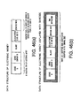
transmission system used for digital terrestrial
broadcasting and electronic commerce using
communications.
Background Art
Regardless of the type of a transmission path such
as satellite, cable and terrestrial, broadcasting is
being digitalized more and more on a worldwide scale in
recent years. Of these digital broadcasting systems, the
European and Japanese digital broadcasting systems use
an Orthogonal Frequency Division Multiplex (hereinafter
referred to as "OFDM") transmission system.
The OFDM transmission system modulates multiple
carriers orthogonal to one another with information to
be transmitted for every symbol period, multiplexes those
modulated signals and transmits the multiplexed signal.
When the number of carriers used increases, the symbol
period of each modulated signal becomes extremely long,
and therefore the OFDM transmission system is
characterized in that it is less susceptible to multi-path
interference.
Furthermore, the OFDM transmission system provides
a redundant period called a "guard period" for every symbol
period, thereby prevents interference between symbols
and further enhances resistance to multi-path
interference. Such a redundant period can be provided
because the symbol period of an OFDM signal is extremely
long and a reduction of the transmission capacity due
to the addition of the redundant period can be confined
within an allowable range.
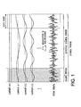
FIG.1 is a schematic view showing a configuration
of an OFDM signal. Hereinafter, a period necessary to
transmit information will be referred to as an "effective
symbol period and the effective symbol period plus a guard
period" as a whole will be referred to as a "symbol period".
As shown in the hatching in the figure, the guard period
of the OFDM signal is a cyclic copy of the last part (copy
part) of the effective symbol period.
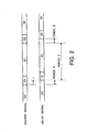
Then, FIG.2 will explain how the guard period
increases the resistance to multi-path interference. A
desired signal or a delay signal in the figure denotes
an OFDM signal that has arrived with a time difference
of τ and G1 and G2 denote guard periods of the first and
second symbols respectively and S0, S1 and S2 denote
effective symbol periods of the 0th, first and second
symbol respectively. Here, the desired signal and the
delay signal receive different symbols during period A
and period B and receive the same signal during period
C. That is, as far as time difference τ is shorter than
the guard period, interference between symbols by the
delay signal remains within the guard period and never
adversely affects the effective symbol period of the
desired signal.
Using the OFDM transmission system as the
transmission system for digital terrestrial broadcasting
makes it possible to implement an SFN (Single Frequency
Network) that constructs a relay network using a single
frequency by capitalizing on this feature of high
resistance to multi-path interference and use frequency
resources effectively.
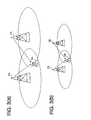
FIG.3(a) shows a case where a large-scale SFN is
constructed using a high power relay station and FIG.3 (b)
shows a case where a small-scale SFN is constructed using
a small power relay station. When FIG.3(a) is compared
with FIG.3(b), the distance between relay station 1A and
relay station 2A is larger in FIG.3(a) and the time
difference until a broadcast signal arrives from the
respective relay stations at reception point 3A is also
greater. Therefore, constructing the large-scale SFN
shown in FIG.3(a) requires a longer guard period than
constructing the small-scale SFN shown in FIG.3(b).
However, taking a longer guard period requires an
increased redundant time accordingly, and for all the
increased symbol period based on the OFDM transmission
system, reducing the transmission capacity poses a
problem when high definition television (hereinafter
referred to as "HDTV") video signals with a high volume
of information are broadcast.
Therefore, when minimizing the reduction of
transmission capacity due to a guard period to construct
a large-scale SFN, it is advantageous to take a longer
symbol period.
On the other hand, the digital terrestrial
broadcasting system in Japan adopts Differential
Quaternary Phase Shift Keying (hereinafter referred to
as "DQPSK") or time interleave that scatters data of
symbols adjacent in terms of time as the modulation system
of each carrier, and thereby allows stable reception even
in a mobile unit reception environment where the
transmission path characteristic changes with time.
In this case, a shorter symbol period is less
susceptible to time variations and allows stable
reception performance even during a high-speed movement.
Thus, an optimal symbol period length varies
depending on the service contents when HDTV video images
are broadcast using a large-scale SFN or when services
are broadcast to a mobile unit traveling at high speed,
etc.
In order to respond to such a demand, as shown in
FIG.4, the digital terrestrial broadcasting system in
Japan provides three types of mode with different
effective symbol period lengths and four types of guard
period ratio (ratio of guard period length to effective
symbol period length) for the respective modes.
Hereafter, this combination of a total of 12 types will
be referred to as "transmission mode". Of these types,
for example, both the guard period ratio 1/8 and the guard
period ratio 1/4 in mode 3 have the same guard period
length of 126µ sec.
Once the locations of relay stations of a broadcaster
are determined, it is possible to estimate a maximum value
of differences in time required for a broadcast signal
to arrive from each relay station at a reception point
within the service area and a necessary guard period length
is determined from the numerical value. This numerical
value varies from one relay network to another, and
therefore the guard period length and the accompanying
effective symbol period length may vary depending on the
region or broadcaster etc.
Furthermore, when the guard period length
determined by a relay station is, for example,
aforementioned 126µsec, the broadcaster can select
whether the guard period ratio in mode 3 should be set
to 1/8 or the guard period ratio in mode 2 should be set
to 1/4. At this time, it is also possible to switch between
these two transmission modes depending on the service
content of a program, for example, using the guard period
ratio 1/8 in mode 3 to increase the transmission capacity
for a program broadcasting HDTV images and the guard period
ratio 1/4 in mode 2 to provide services to high-speed
mobile units stably for a program broadcasting services
for mobile units.
Furthermore, after a broadcasting service is
started, when the distance between relay stations
decreases due to additions of relay stations and the
aforementioned time difference decreases, the necessary
guard period length also decreases. However, since the
guard period is a redundant period which would originally
be unnecessary for transmission of information, the guard
period length is naturally changed to a minimum necessary
length from the standpoint of effective use of frequency
resources.
As shown above, the transmission mode expressed by
a combination of the effective symbol period length and
guard period ratio may vary depending on the region or
broadcaster and a certain broadcaster may also change
with time.
On the other hand, demodulation processing for an
OFDM signal on the receiving side extracts only the period
necessary for demodulation from a received signal,
applies Fast Fourier Transform (hereinafter referred to
as "FFT") to the signal, thereby separates the carriers
sent after being multiplexed and then applies detection
processing according to each carrier modulation system.
In the process of that processing, the transmission mode
such as an effective symbol period length and guard period
ratio constitutes indispensable information.
Thus, when the transmissionmode of a received signal
is unknown, the method for automatically acquiring the
aforementioned transmission mode information from the
received signal itself through signal processing is
disclosed in Patent Gazette No.2863747 or Patent Gazette
No.2879034, etc.
The prior arts disclosed in these literatures take
advantage of the fact that a guard period of an OFDM signal
is a cyclic copy of a signal at the tail of an effective
symbol period, calculate a correlation between the
received signal and a signal obtained by delaying the
received signal by an estimated effective symbol period
length, analyze the waveform of this correlation signal,
and thereby decide the effective symbol period length
and guard period length.
Conventionally, people have been conducting various
kinds of electronic commerce, for example, purchasing
products using a communication network such as the
Internet. In such electronic commerce, products to be
traded are posted on a homepage, for example. The user
accesses this homepage from his/her own terminal over
the Internet, selects a product to be purchased and at
the same time enters user information that identifies
the user.
Then, the user enters a credit number and an ID during
a settlement period and specifies a settlement method
such as payment on delivery. A homepage operating
organization (center) authorizes the placement of an
order for the product upon completion of such entries
and a supplier that has received the order delivers the
product to the user and receives payment according to
the specified settlement method.
However, according to the transmission system using
the aforementioned OFDM system, an OFDM signal is received
and then the transmission mode is decided from the received
signal, and therefore the time after the user selects
desired information until the user receives the
information includes a time for the above-described
decision, which prevents quick response to the user's
demand.
Furthermore, when a broadcaster switches between
transmission modes according to the service content of
a program as described above, demodulation processing
is temporarily broken up immediately after the switchover
and it is not until transmission mode decision processing
is recovered from that state and the decision result is
obtained that it is possible to output information after
the switchover of the transmission mode, and therefore
a supply of information to the user is suspended for a
long time.
Furthermore, the aforementioned electronic
commerce using a communication network involves problems
concerning security and complexity of settlement. With
regard to the security with the use of a credit card,
there is concern about falsification, etc. With regard
to settlement, settlement with a simpler procedure is
accompanied by lower reliability of security. On the
other hand, attempting to achieve both the security and
ease of settlement results in an increase in the scale
of system configuration.
Disclosure of Invention
It is an object of the present invention to provide
an electronic commerce system with a simple configuration
capable of achieving both reliability of security and
ease of settlement.
This object is attained by providing a portable
terminal with a reception section for receiving product
information and service information and a barcode
formation section for forming a barcode based on the
received information, displaying the barcode formed by
the barcode formation section on a display section,
reading this barcode using a barcode reader provided for
a terminal at a shop, etc. and thereby conducting
electronic commerce.
Brief Description of Drawings
FIG.1 is a schematic diagram showing a conventional
configuration of an OFDM signal;
FIG.2 is a schematic diagram illustrating an effect
of a guard period;
FIG.3(a) is a schematic diagram showing a
configuration of a large-scale SFN;
FIG.3(b) is a schematic diagram showing a
configuration of a small-scale SFN;
FIG.4 illustrates a ratio of a guard period length
to an effective symbol period length in each mode according
to a digital terrestrial broadcasting system;
FIG.5 is a block diagram showing a configuration
of adigital terrestrial broadcasting reception apparatus
according to a first embodiment of the present invention;
FIG.6 is a block diagram showing an internal
configuration example of the OFDM demodulation section
in FIG.5;
FIG.7 illustrates a content of TMCC information;
FIG.8(a) is a flow chart showing a preset mode of
the CPU in FIG.5;
FIG.8(b) is a flow chart showing an audiovisual mode
of the CPU in FIG.5;
FIG.9 illustrates a content of the storage section
in FIG.5;
FIG.10 is a block diagram showing a configuration
of an OFDM signal transmission system according to a second
embodiment of the present invention;
FIG.11 is a block diagram showing a configuration
of an OFDM signal transmission system according to a third
embodiment of the present invention;
FIG.12 is a block diagram showing a configuration
of an OFDM signal transmission system according to a fourth
embodiment of the present invention;
FIG.13 is a flow chart showing an operation of the
CPU in FIG.12;
FIG.14 illustrates a content of program
information;
FIG.15 is an overall view of a T mode cellular phone
system according to a fifth embodiment of the present
invention;
FIG.16 illustrates a relationship between movements
of a T mode cellular phone and a plurality of service
areas;
FIG.17 is a block diagram showing a configuration
of a cellular base station according to the fifth
embodiment;
FIG.18(a) illustrates reception data in standby
mode;
FIG.18(b) illustrates reception data in
communication mode;
FIG.19 illustrates transmission information and a
content of transmission information;
FIG.20(a) illustrates bands of a normal
broadcasting station;
FIG.20(b) illustrates bands of a broadcasting
station that carries out partial broadcasting;
FIG.20(c) illustrates a band diagram of a dedicated
data broadcasting station;
FIG.21 is a block diagram showing a configuration
of a T mode cellular phone;
FIG.22 illustrates a transmission information
pattern table, frequency control and time control tables;
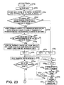
FIG.23 is a flow chart of a procedure for acquiring
transmission information, first and second transmission
information;
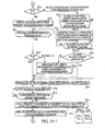
FIG.24 is a flow chart of a procedure for converting
transmission information to pattern information;
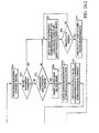
FIG.25 is a flow chart of a procedure for acquiring
transmission information of a field intensity control
system;
FIG.26 is a flow chart of a procedure for acquiring
transmission information of a frequency control system;
FIG.27 is a flow chart of a procedure for acquiring
transmission information and first and second
transmission information;
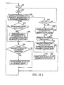
FIG.28 is a flow chart of a procedure for acquiring
transmission information and first and second
transmission information;
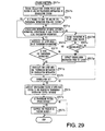
FIG.29 is a flow chart of a procedure for converting
transmission information to pattern information;
FIG.30 illustrates a procedure for authenticating
a cellular phone, virtual shop and real shop according
to a sixth embodiment of the present invention;
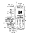
FIG.31(a) illustrates a menu screen of a cellular
phone according to the sixth embodiment of the present
invention;
FIG.31(b) illustrates a screen in barcode mode;
FIG.31(c) illustrates an airplane ticket selection
screen;
FIG.31(d) illustrates a musical entertainment
selection screen;
FIG.31(e) illustrates an attraction selection
screen;
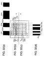
FIG.32(a) illustrates a display pitch of a main
display section;
FIG.32(b) illustrates pixels of the main display
section;
FIG.32(c) illustrates pixels of a sub-display
section;
FIG.32(d) illustrates a display pitch of a
sub-display section;
FIG.33(a) illustrates an A-A' sectional view of the
display element in FIG.32;
FIG.33(b) illustrates an B-B' sectional view of the
display element in FIG.32;
FIG.34 illustrates a barcode reader;
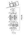
FIG.35 is a block diagram showing a configuration
of an optical detection section and display section;
FIG.36 is a flow chart showing a display procedure
of the display section;
FIG.37 illustrates configurations of a server,
client and actual shop;
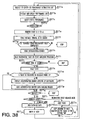
FIG.38 is a flow chart showing an admission
processing procedure;
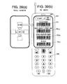
FIG.39(a) illustrates a menu screen of a cellular
phone;
FIG.39(b) illustrates a screen in barcode mode;
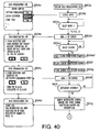
FIG.40 is a flow chart of a screen display of a
cellular phone;
FIG.41 is a flow chart of a screen display of a
cellular phone;
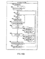
FIG.42(a) is a top view of a portable device;
FIG.42(b) illustrates a barcode display;
FIG.43(a) is a timing chart of a barcode screen
display when each barcode is displayed at predetermined
intervals;
FIG.43(b) is a timing chart of a barcode screen
display when a barcode is displayed at intervals only
at the start of data;
FIG.44 is a timing chart of a barcode screen display;
FIG.45(a) is a timing chart of a barcode screen
display;
FIG.45(b) illustrates a detection signal by a
barcode reader;
FIG.45(c) illustrates a quantity of reflected
light;
FIG.46(a) illustrates a data structure of
electronic money;
FIG.46(b) illustrates a data structure of encrypted
electronic money;
FIG.47 is a block diagram showing a configuration
of a cellular phone when a barcode is automatically
displayed through a local communication;
FIG.48(a) is a flow chart showing a processing
procedure of a cellular phone that selectively
establishes a communication session through a local radio
communication with a barcode;
FIG.48(b) is a flow chart showing a processing
procedure of a POS terminal that selectively establishes
a communication session through a local radio
communication with a barcode;
FIG.49(a) is a flow chart showing a processing
procedure of a cellular phone that establishes a
communication session through a local radio communication
by displaying a random number as a session ID with a
barcode;
FIG.49(b) is a flow chart showing a processing
procedure of a POS terminal that establishes a
communication session through a local radio communication
by displaying a random number as a session ID with a
barcode;
FIG.50 is a flow chart showing a processing procedure
of a cellular phone that automatically displays a barcode
through a local communication; and
FIG.51 illustrates a structure of coupon data when
a barcode is automatically displayed through a local
communication.
Best Mode for Carrying out the Invention
With reference now to the attached drawings,
embodiments of the present invention will be explained
in detail below.
Clocks and control signals, etc. necessary for
operation of each block in block diagrams except those
necessary to explain operations of the present invention
will be omitted as it would complicate drawings otherwise.
(1) First embodiment
FIG.5 is a block diagram showing a configuration
of digital broadcasting reception apparatus 10A according
to a first embodiment of the present invention.
This embodiment assumes a use mainly in a fixed
reception environment such as household when the
transmission mode does not change in a short time such
as a program unit though the transmission mode may vary
depending on the region or broadcaster, etc.
In FIG.5, antenna 101 supplies a digital broadcast
signal to an input of tuner 102. This tuner 102 selects
a signal of a channel of the user' s choice from the digital
broadcast signal supplied from antenna 101, converts the
frequency of the signal from a radio frequency band to
a base frequency band and supplies the output to an input
of OFDM demodulation section 103. OFDM demodulation
section 103 applies processing such as demodulation and
error correcting to the digital broadcast signal of the
base frequency band to reproduce the transmission
information string and supplies the output to an input
of information source decoding section 104.
Here, the transmission information string has a
format called "transport stream (hereinafter referred
to as "TS") of MPEG2 (Moving Picture Experts Group 2)
in which video information and speech information
subjected to high efficiency coding (compression) and
data, etc. are multiplexed.
Information source decoding section 104 separates
the transmission information string into video
information, speech information and data, decodes the
video information and speech information subjected to
high efficiency coding, then supplies the decoded video
information and speech information to an input of output
section 105 and supplies the data to CPU (Central
Processing Unit) 107 via information bus 110. Output
section 105 presents the decoded video, speech or a message,
etc. from CPU 107 to the user.
Input section 106 receives an instruction from the
user and transmits the content of the instruction to CPU
107. CPU 107 controls each block through control bus 109
based on instructions, etc. of the user from the input
section. CPU 107 further receives the data separated by
information source decoding section 104 or outputs a
message, etc. to be presented to the user to output section
105 through information bus 110. Storage section 108
stores information required for this digital broadcasting
reception apparatus 10A to operate.
Here, input section 106 includes not only buttons,
etc. provided for this digital broadcasting reception
apparatus 10A itself but also buttons provided for an
external remote controller, etc. or an interface between
the remote controller and this apparatus.
FIG.6 is a block diagram showing an internal
configuration example of OFDM demodulation section 103
in FIG.5 and the output of tuner 102 is supplied to an
input of quadrature detector 1031 inside OFDM
demodulation section 103. quadrature detector 1031
performs quadrature detector on the digital broadcast
signal of the base band to transform into a complex number
signal made up of an in-phase axis (hereinafter referred
to as "I-axis") and a quadrature axis (hereinafter
referred to as "Q-axis") signal and supplies the output
to guard period elimination section 1032. Guard period
elimination section 1032 removes the guard period from
the output of quadrature detector 1031 based on the
information on the guard period length from control bus
interface (I/F) section 1037 and supplies the output to
an input of Fast Fourier Transform (hereinafter referred
to as "FFT") section 1033.
FFT section 1033 applies FFT to the signal whose
guard period has been removed based on the information
on the effective symbol period length from control bus
I/F section 1037 to separate the carriers sent after being
multiplexed and supplies the output to a first input of
detection section 1034 and an input of demodulation
information decoding section 1036.
Detection section 1034 applies detection processing
to each carrier supplied from the first input based on
the demodulation information (each carrier modulation
system) supplied from the second input and supplies the
output to a first input of error correcting section 1035.
Error correcting section 1035 applies error correcting
processing to the detection result supplied from the first
input based on the demodulation information (depth of
time interleave and error correcting coding rate, etc.)
supplied from the second input and supplies the output
to information source decoding section 104 as the output
of OFDM demodulation section 103.
Demodulation information decoding section 1036
extracts the carrier that transmits demodulation
information from the output of FFT section 1033, applies
detection/error correcting processing to the carrier to
decode the demodulation information and supplies the
output to detection section 1034 and a second input of
error correcting section 1035.
Control bus I/F section 1037 interprets control
information from CPU 107 transmitted through control bus
109 and supplies transmission mode information on the
guard period length and effective symbol period length
to guard period elimination section 1032 and FFT section
1033.
A block such as detection section 1034 may also
actually use transmission mode information to generate
a control signal necessary for operation, but FIG.6 omits
such a case to prevent the drawing from being complicated.
Furthermore, in order for OFDM demodulation section 103
to operate, it is necessary to carry out synchronization
processing such as carrier frequency synchronization,
sampling frequency synchronization, symbol
synchronization and frame synchronization, but that
synchronization processing is omitted for the same reason
here.
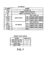
Here, the digital terrestrial broadcasting system
in Japan transmits demodulation information using a
signal called "TMCC (Transmission and Modulation
Configuration Control)" and FIG.7 shows the content.
Next, an operation of the digital broadcasting
reception apparatus of this embodiment will be explained
using the attached drawings. The digital broadcasting
reception apparatus of this embodiment has at least preset
mode and audio-visual mode as its operating modes.
FIG.8 is a flow chart showing an operation of CPU
107 and (a) shows an operation of the CPU in preset mode
and (b) shows an operation of the CPU in audio-visual
mode.
In preset mode, information to identify the current
location is acquired from input section 106 (step S1).
Then, start address A of the channel selection information
corresponding to the identified current location and
information count n is acquired (step S2) and address
A to address A+ (n-1) of the channel selection information
are assigned to button 0 to (n-1) of input section 106
one by one (steps S3, S4, S5 and S6).
Here, an address, postal code, telephone number,
etc. are used as the information to identify the current
location and storage section 108 stores information
associating such information with the start address of
the channel selection information corresponding to each
region and information count beforehand and CPU 107
references the information and can thereby acquire the
start address of the channel selection information
corresponding to the current location and information
count.
In the audio-visual mode, the input of button j to
which the channel selection information address is
assigned in the preset mode is acquired from input section
106 first (step S11). Then, address A+j assigned to
button j is accessed (step S12) to acquire the channel
selection information of address A+j from storage section
108 (step S13). Then, frequency information Fj is
transmitted to tuner 102 (step S14) and transmission
information Mj is transmitted to OFDM demodulation
section 103 (step S15).
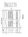
FIG.9 shows an example of the content of storage
section 108 and assignment to the buttons of input section
106. As shown in the figure, frequency information and
transmission mode information are stored at the addresses
as channel selection information.
The above-described configuration of this
embodiment eliminates the need for the user to select
a desired broadcaster, receive a digital broadcast signal
and decide the transmission mode from the received signal,
and can thereby provide desired information in response
to the user's demand immediately.
By the way, the method of storing channel selection
information in storage section 108 has not been explained
in particular, but the channel selection information may
be stored during manufacturing beforehand or the channel
selection information may be updated as required. Using
the latter method makes it possible to respond to a
relatively long-term change of the transmission mode such
that the distance between relay stations is shortened
due to an addition of a relay station after the broad casting
service is started and the guard period length is changed.
Furthermore, as the method of acquiring new channel
selection information, it is possible to use a method
of multiplexing the transmission information string in
a digital broadcast signal with the channel selection
information, a method of providing separate communication
means and acquiring channel selection information via
a communication channel or a method of acquiring channel
selection information via a recording medium, etc.
(2) Second embodiment
FIG.10 is a block diagram showing a configuration
of an OFDM signal transmission system according to a second
embodiment of the present invention. In FIG.10,
components assigned the same reference numerals as those
in FIG.5 operate in the same way as in the first embodiment.
This embodiment assumes a use mainly in a mobile
reception environment such as an automobile and cellular
phone when the transmission mode does not change in a
short time such as a program unit though the transmission
mode may vary depending on the region or broadcaster,
etc.
Furthermore, this embodiment operates in the same
way as the first embodiment except that it identifies
the current location using a Global Positioning System
(hereinafter referred to as "GPS").
In FIG.10, GPS antenna 111 of digital broadcasting
reception apparatus 10B supplies signals from GPS
satellites 20A, 20B and 20C to an input of GPS processing
section 112. GPS processing section 112 measures the time
required for a signal to arrive from each satellite using
pseudo-random codes included in signals from GPS
satellites 20A, 20B and 20C, thereby calculates the
distance from each satellite and identifies the current
location based on the principle of triangulation. CPU
section 107 uses the current location identified by GPS
processing section 112 in the preset mode explained in
the first embodiment.
The above-described configuration of this
embodiment eliminates the need for the user to select
a desired broadcaster, receive a digital broadcast signal
and decide the transmission mode from the received signal,
and can thereby provide desired information in response
to the user's demand immediately and furthermore always
identify the current location using GPS even in a mobile
reception environment in which the current location is
changing from moment to moment, which eliminates the need
to frequently enter information to identify the current
location according to the movement.
(3) Third embodiment
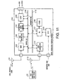
FIG.11 is a block diagram showing a configuration
of an OFDM signal transmission system according to a third
embodiment of the present invention. In FIG.11,
components assigned the same reference numerals as those
in FIG.5 operate in the same way as in the first embodiment.
This embodiment assumes a use mainly in a mobile
reception environment such as an automobile and cellular
phone as in the case of the second embodiment when the
transmission mode does not change in a short time such
as a program unit though the transmission mode may vary
depending on the region or broadcaster, etc.
Furthermore, this embodiment operates in the same
way as the first embodiment except that it identifies
the current location using a position registration
function in a cell-based mobile communication system.
The cell-based mobile communication system is a
system whereby a service area is divided into multiple
small areas called "cells", a base station is placed in
each cell and the base station tracks and accesses the
user according to the movement of the user. Since the
user moves across a plurality of cells in this system,
it is necessary to always localize the mobile unit to
know the cell in which the mobile unit is. This system
is also provided with a position registration function
as the control technology indispensable to smoothly
continue communication when the mobile unit changes from
one cell to another.
Using the position registration function, the
mobile unit acquires position information from the base
station, registers the information in the own unit and
also notifies it to a network. Then, upon detection of
any position change, the mobile unit updates the position
registration in the own unit and also notifies it to the
network. Furthermore, when power of the mobile unit is
turned off and turned on again, the mobile unit compares
the position information from the base station at that
time with the position information in the own unit and
if both position information pieces do not match, the
mobile unit updates the position registration in the own
unit and notifies the new position information to the
network.
In FIG.11, radio communication antenna 113 of
digital broadcasting reception apparatus 10C supplies
a signal from radio communication base station 30 to radio
communication interface (I/F) section 114 and also emits
a signal supplied from radio communication I/F section
114 to radio communication base station 30. Radio
communication I/F section 114 extracts the position
information included in the signal from radio
communication base station 30 supplied from radio
communication antenna 113, identifies the current
location and transmits the information to CPU 107. CPU
107 uses the current location information transmitted
from radio communication I/F section 114 in the preset
mode explained in the first embodiment.
The above-described configuration of this
embodiment eliminates the need for the user to select
a desired broadcaster, receive a digital broadcast signal
and decide the transmission mode from the received signal,
and can thereby provide desired information in response
to the user's demand immediately and at the same time
can always identify the current location using the
position registration function in a cell-based mobile
radio communication even in a mobile reception
environment in which the current location changes from
moment to moment, which eliminates the need to frequently
enter information to identify the current location
according to the movement of the mobile unit.
(4) Fourth embodiment
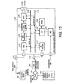
FIG.12 is a block diagram showing a configuration
of an OFDM signal transmission system according to a fourth
embodiment of the present invention. In FIG.12,
components assigned the same reference numerals as those
in FIG.5 and FIG.11, operate in the same way as in the
first embodiment and the third embodiment.
This embodiment assumes a use mainly in a mobile
reception environment such as an automobile and cellular
phone when the transmission mode varies depending on the
region or broadcaster, etc. and the transmission mode
changes in a short time such as a program unit.
Furthermore, this embodiment transmits program
information including transmission mode information
using a channel different from the channel for
broadcasting and uses the information when a channel is
selected.
In FIG. 12, program information distribution center
50 acquires/stores program information frombroad casting
station 60 through communication channel 40 and
distributes the program information according to a
request from digital broadcasting reception apparatus
10D.
On the other hand, unlike the first to third
embodiments, digital broadcasting reception apparatus
10D can provide the user's desired information without
the preset mode as the operating state.
FIG.13 is a flow chart showing an operation of CPU
107 in digital broadcasting reception apparatus 10D.
First, a menu is presented to the user through output
section 105 (step S20). When the user desires digital
broadcasting (steps S21, S23), digital broadcasting
reception apparatus 10D sends a request for program
information distribution to program information
distribution center 50 using radio communication I/F
section 114 and radio communication antenna 113 (step
S23). At this time, not only the request but also the
current location are notified using the position
registration function explained in Embodiment 3.
Upon reception of the distribution request and
current location from digital broadcasting reception
apparatus 10D through radio communication base station
30 and communication channel 40, program information
distribution center 50 distributes information on the
program supplied by the broadcasting station that can
be received at the current location to digital
broadcasting reception apparatus 10D through
communication channel 40 and radio communication base
station 30 (step S23).
CPU 107 in digital broadcasting reception apparatus
10D acquires the program information from program
information distribution center 50 through radio
communication antenna 113 and radio communication I/F
section 114 and stores the information in storage section
108 (step S24) and presents a list of programs that can
be received at the current location through output section
105 (step S25).
Then, when the user selects a desired program from
the above-described list (step S26), CPU 107 acquires
the channel selection information corresponding to the
above program from storage section 108 (step S27),
transmits the frequency information to tuner 102 (step
S28) and transmits the transmission mode information to
OFDM demodulation section 103 (step S29).
FIG.14 shows an example of the content of the program
information. In this example, the program information
includes titles and genres as content information,
frequency information and transmission mode information
as channel selection information and start time and end
time as time information for each program.
The above-described configuration of this
embodiment makes it possible not only to provide a program
of the user's choice without a preset operation but also
to always identify the current location using the position
registration function in a cell-based mobile radio
communication even in a mobile reception environment in
which the current location changes from moment to moment,
eliminating the need to frequently enter information to
identify the current location according to the movement
of the mobile unit.
By the way, if the system is set so that the program
information also including schedules a certain time ahead,
for example, within 24 hours or within one week is
distributed and digital broadcasting reception apparatus
10D stores the content in storage section 108, such an
operation that the user reserves a desired program and
the program is automatically presented at the time of
starting the program will also be available.
Furthermore, this embodiment has described that
channel selection information is associated with the
program as the program information, but in the case where
the transmission mode does not change in a short time
such as a program unit though the transmission mode may
vary depending on the region or broadcaster, etc., program
information distribution center 50 can also distribute
the channel selection information associated with the
broadcaster and digital broadcasting reception apparatus
10D can also assign the information to the buttons, etc.
of input section 106 as in the case of the first to third
embodiments.
Furthermore, if the transmission mode changes after
such assignment or if the current location changes due
to movement, digital broadcasting reception apparatus
10D notifies the user via output section 105 that it is
impossible to receive and requests program information
distribution center 50 for the redistribution of the
information, presents a new list and updates the
assignment information, and can thereby improve
convenience for the user.
(5) Fifth embodiment
The fifth embodiment will describe transmission
information management carried out by a transmission
information control section made up of a CPU. Frequency
control of transmission information, time control such
as elapsed time after use, field intensity control,
control and prediction of channel region identification
service content, etc., information compression using
patterned information, etc. will be explained in detail.
Transmission information is included in either or both
of transmission data of a cellular phone from a base station
or transmission data from a TV broadcasting station, but
this embodiment will describe an example of information
sent from a cellular phone base station.
(5-1) Overall configuration
FIG.15 is an overall view showing a relationship
between TV reception type cellular phone 501, terrestrial
TV station 502 and cellular phone base station 503.
Terrestrial TV station 502 sends broadcast signal 504
in downward uni-direction to cellular phone 501, which
receives part of data of a specific channel of this
broadcast signal 504. Broadcast signal 504 is also sent
to a fixed receiver having fixed antenna 514, that is,
digital TV receiver 505.
(Cellular reception) On the other hand, TV reception type
cellular phone 501 receives downlink signal 506, 506a
or 506b which are signals from one or a plurality of
cellular phone base stations 503, 503a or 503b near
cellular phone 501, and sends uplink signal 507, 507a
or 507b to any one or a plurality of stations cellular
phone base stations 503, 503a or 503b. Cellular phone
base station 503 is connected to public network 511 via
cellular phone control section 510. In the case of a
specific cellular phone service company, cellular phone
control section 510 is connected to Internet 513 through
server 512.
(Fixed reception) As described above, in the case where
transmission data is also received by TV receiver 505
of digital TV with a fixed antenna 514 with high sensitivity
such as a household TV, instead of the aforementioned
partial broadcast data, all data in a specific channel
is received. Some of TV receivers 505 are connected to
local fixed telephone station 515 via a telephone line
and can access Internet 513 via public network 511.
There are great differences in reception conditions
when the aforementioned digital TV broadcast data is
received by cellular phone 501 and when the digital TV
broadcast data is received by fixed TV receiver 505. When
the digital TV broadcast data is received by TV reception
type cellular phone 501, the receiver moves. When the
aforementioned SFN (Single Frequency Network) channel
broadcast data is received, the receiver moves from one
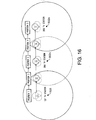
place to another as shown in FIG. 16 and even if the receiver
moves into the service area of the next broadcasting
station, it receives a TV signal with the same frequency
having completely the same information, and therefore
the receiver has no trouble with TV reception and continues
to receive the broadcast data seamlessly and its movement
causes no problem.
However, in the case of receiving broadcast data
of a non-SFN channel, in the process in which the receiver
moves from position 1 (FIG.16) to position 5, the receiver
using the conventional method cannot receive signals from
first TV station 502 in certain points between position
2 and position 3 due to a reduction of field intensity.
Therefore, the user of the TV reception type cellular
phone switches between frequencies using a tuner in an
attempt to search for the channel corresponding to the
broadcast data. Then, the user finally comes to know the
presence of second TV station 502a and tries to receive
the broadcast data. However, in the case of digital TV
broadcasting, unlike analog broadcasting, the receiver
cannot manage to receive signals by simply tuning the
frequency. It is impossible to receive physical layers
without matching transmission information parameters
such as a guard time and error coding gain. For this reason,
the conventional TV reception type cellular phone changes
parameters in various ways in a round-robin system in
an attempt to find which parameter is best suited.
There are several tens to several thousands of types
of combinations of parameters. For this reason, it takes
time to match parameters. After obtaining the
demodulation information of the first layer of the
received signal, it is possible to demodulate the second
and higher layers, and therefore it is possible to obtain
information. Since it takes time to determine parameters
in this way, if frequencies are included, there is a period
of time, for example, several seconds to a maximum of
several tens of seconds during which no TV reception signal
can be output. In the case where the channel through which
the receiver managed to receive signals is not
broadcasting the service desired by the user, the user
switches over to another channel to continue to search
for the service of the user's choice. In this case, too,
it takes time to determine parameters and therefore it
takes further extra time.
The present invention receives at least a base
station ID from downlink signal 506 of cellular phone
base station 503, obtains positional information from
the base station ID, obtains transmission information
including parameters to demodulate the modulated signal
of TV broadcasting from the positional information and
demodulates the signal. Or the present invention can skip
the channel demodulation procedure by reading the
transmission information of the regional TV broadcasting
station corresponding to the base station ID obtained
using a transmission information control database which
is a correspondence list pre-recorded in the cellular
phone. Therefore, it is possible to shorten a channel
reception time or channel switching time.
Here, FIG.17 shows a configuration of cellular phone
base station 503. Base station 503 comprises cellular
phone base station antenna 516, base station
transmission/reception circuit 517, communication
control section 518 called "RNC (Radio Network
Controller)" connected therewith through a channel in
ATM (Asynchronous Transmission Mode), etc. and PDSL
(Panasonic digital soft laboratory) 520 connected to
backbone 519. These are the blocks required for
communications by cellular phones.
Cellular base station 503 transmits data as shown
in FIG.18. That is, cellular phone data 522 which is basic
information of transmission data in standby mode in
FIG.18(a) and cellular phone data 523 which is basic
information in communication mode in FIG.18(b) include
base station ID 521 or base station number 521. Therefore,
the base station ID can be received in all cellular phone
service areas and this base station ID can be used as
auxiliary information for TV reception.
Furthermore, base station 503 according to the
present invention sends part or the whole of TV reception
transmission information data 524 necessary for TV
reception. In the case of this transmission information,
transmission information of another broadcasting station
can also be sent included in the TV broadcast signal.
In this case, once TV reception is successful, it is
possible to acquire transmission information of other
stations, and therefore effects similar to those in the
case of base station transmission can be obtained.
However, once TV reception is suspended, information on
the base station is required.
(5-2) Explanations of first and second transmission
information
TV reception data 524 in FIG.18 will be explained.
FIG.19 is a flow chart showing a specific content of this
TV reception data in compliance with the ISDB-T standard
which is the OFDM-based digital TV broadcasting standard
in Japan. An OFDM-based TV broadcasting standard such
as DVB standard also has similar parameters.
FIG.18(a) illustrates transmission data in standby
mode of a cellular phone, and the cellular phone uses
a first highly resistant channel and sends cellular phone
data 522, that is, base station ID 521 to identify the
base station and data of a free cellular phone
communication channel. As described above, the cellular
phone base station according to the present invention
sends TV reception data 524 necessary for
tuning/demodulation of digital TV broadcasting in
addition to this.
TV reception data 524 includes transmission
information 528 that indicates the channel of the TV
broadcasting station currently in transmission.
Transmission information 528 includes channel IDs of all
channels currently in transmission. Channels in
transmission 527 are received and used not only by fixed
reception stations but also by trains and automobiles.
When partial broadcasting is dedicated to a T mode cellular
phone, limiting partial broadcasting to the channel ID
of the broadcasting station currently providing services
has an effect of reducing the amount of information.
A case of the ISDB-T standard is shown as an example.
As shown in FIG.20(a), since broadcasting data 528 of
one channel of HD broadcasting which is TV broadcasting
with the same transmission resistance and high resolution
or 4 to 5 channels of SD broadcasting which is TV
broadcasting with normal resolution is sent using one
broadcasting with one broadcasting band of 6 MHz or 8
MHz, channel in transmission 527 can be used.
However, in this embodiment as shown in FIG.20(b),
one or two specific partial segments 529 of the 13 segments
has stronger resistance than other general segments 530.
For example, resistance is increased by changing
parameters and lowering the information transmission
efficiency, for example, using QPSK for specific partial
segments as opposed to using 64QAM for general segments
as the modulation system, or using 2K for the first as
opposed to using 8K for the latter as the FFT size.
This embodiment calls this layered type
broadcasting "partial transmission" or "partial
broadcasting". Since partial segment 529 is broadcast
with resistant parameters, partial segment 529 can be
received even by a small antenna such as antenna 531
(FIG.21) of a cellular phone. On the other hand, in the
case of partial broadcasting, since the frequency band
used is narrow and the transmission efficiency is lower,
the transmission data capacity decreases drastically from
hundred Mbps to a little over 1 Mbps.
However, in the case of a mobile device such as a
cellular phone, the display screen is as small as 1 inch
to several inches and using MPEG4 which provides a low
transmission rate of several tens of Kbps to several
hundreds of Kbps with a high compression rate or a wavelet
system makes it possible to provide a screen of quality
without any audio-visual trouble.
Furthermore, data broadcasting using a single
segment 532 or three segments as shown in FIG.20(c) is
defined by ISDB-T and this is also suitable for cellular
reception as in the case of "partial transmission". This
specification also includes this data transmission in
"partial transmission".
According to FIG.18 again, transmission information
528 includes the data of above-described channel 533 in
partial transmission for cellular phones that perform
such mobile unit reception. A channel number
(hereinafter abbreviated as "ch") being broadcast only
indicates a frequency band assigned in each country. For
example, in an area away from another area broadcasting
15ch with a distance enough to prevent mutual interference,
a different broadcasting station provides a completely
different broadcasting service using the same channel,
that is, the same frequency.
TV reception using a cellular phone requires both
stations to be identified because the mobile unit is moving.
Thus, identification information 534 is added to identify
the broadcasting stations with the same channel. It is
not until identification information 534 is added that
it is possible to identify each broadcasting station.
For example, even the same 15ch is defined as 15-1ch for
the first in area A and 15-2ch for the latter in area
B.
Thus, defining channels of each broadcasting
station by adding an identifier capable of identifying
different broadcasting stations with the same frequency
for different areas makes it possible to identify
broadcasting stations with different areas using the same
frequency band, that is, the same channel. This makes
it possible to prevent misoperation caused by settings
of wrong transmission parameters due to wrong recognition
of a broadcasting station with the same channel.
Furthermore, the base station according to the
present invention transmits field intensity information
535 for each channel. It is possible for the receiver
to control this information to select a reception channel
with higher priority from a channel group with strong
field intensity, providing more stable reception.
Then, transmission information necessary for
demodulation will be explained in detail using FIG.18
and FIG.19. First transmission information 526 includes
transmission frequency 536 that indicates a channel to
be transmitted, partial broadcasting identifier 550, FFT
size 537, guard ratio 538 that indicates the ratio of
a symbol time to a guard interval and transmit power 539
of a broadcast antenna as shown in FIG.19 or FIG.18.
As shown in FIG.19, through first transmission
information 526, it is possible to know various parameters
before the broadcast signal or demodulation. For this
reason, with the setting of the first parameters, data
in the first layer of layer transmission by OFDM or PSK
is demodulated. At the same time, demodulation
information 541 to demodulate the second layer, for
example, TMCC data of the ISDB-T standard or TPS data
of the DVB standard, etc. can be acquired from the data
demodulated from the first layer. This demodulation
information allows all data to be demodulated.
In the case of mobile unit reception for applications
such as cellular phones and automobiles, parameters of
first transmission information 526 change frequently
because these mobile units move across a plurality of
service areas of broadcasting stations. When parameters
of the first transmission information are unknown, there
is no way other than attempting to set all parameters
according to a round-robin system and try demodulation.
Since there are a total of 12 combinations of the first
transmission information in the case of the ISDB-T
standard, it is necessary to perform setting operations
a maximum of 12 times to determine parameters in the first
layer. For this reason, it takes time to output reception
data, while the present invention has an effect of
reproducing data in the first layer instantaneously.
Since this data in the first layer includes
demodulation information 541 containing parameters, etc.
necessary to demodulate layer signals from the second
layer onward or to correct errors, when a first step to
demodulate the first layer is followed by a second step
to demodulate demodulation information 541 and a third
step to extract parameters from the demodulation
information, it is possible to demodulate the second layer
using demodulation information 541.
However, as described above, in mobile applications,
parameters of transmission information frequently change.
If demodulation information 541 of this second layer can
be known beforehand, all transmission parameters can be
acquired, and therefore data can be demodulated even
faster. This high-speed demodulation system will be
explained using FIG.18 and FIG.19. FIG.18(a) is a system
for sending both first transmission information 526 and
second transmission information 525 from a cellular base
station in standby mode.
First, the effects will be explained. In standby
mode, the base station sends transmission information.
Thus, a portable terminal such as PDS and portable TV
which have no uplink, that is, transmission function,
can receive this information, and therefore this system
has an effect of drastically shortening a reception time
when data is received for the first time or when the channel
is changed.
In countries including Japan, transmission from a
device with a transmission function such as a cellular
phone is prohibited in trains or hospitals, but even in
such a case, if the mode is changed to "T mode" using
a switch, it is possible to receive and acquire transmitted
information without transmitting a signal from the
cellular phone, which widens the application range of
broadcasting reception of cellular phones.
Furthermore, when the T mode switch is turned on
before entering an area where the use of the cellular
phone is prohibited, the user sends the own area, operating
time zone, portable terminal ID and broadcasting station
ID of the broadcasting station that receives the call
data to the broadcasting station via the base station.
Then, when a call arrives at the cellular phone, a broadcast
signal including the own portable terminal ID is sent
via the broadcasting station, and therefore the arrival
of a call at the own terminal is detected, notified to
the user through a vibration motor, etc. thus providing
a paging effect, that is, performing notification of
reception.
In the T mode including the call system of the present
invention, strong transmission radio wave is not
transmitted, which has an effect of reducing the total
amount of radio wave emitted from the cellular phone and
reducing the influence of transmission radio wave on the
human body.
A method of controlling transmission information
parameters by patterning them and compressing the
information will be explained. According to the second
transmission information in FIG.18(a), second
transmission information 525 includes parameters such
as modulation system 551, coding rate 552, time interleave
length 553 and these parameters vary from one channel
to another. More specifically, as shown in the lower part
of FIG.19, in the case of the ISDB-T standard, there are
three modes of modulation system 551; DQPSK, 16QAM, 64QAM
and five modes of coding rate 552 such as error correcting
Viterbi, and four modes of time interleave length 553,
giving a total of 60 combinations of parameters of the
second transmission information.
There are 12 types of parameters of the first
transmission information and if partial broadcasting
identifier 550 is included, there are a total of 24
combinations, giving 60 × 24 = 1440 combinations in total.
These are shown as parameter setting examples of the
respective channels at the bottom right of FIG.19.
However, operations of the broadcasting station in real
digital TV broadcasting are complicated, and each
broadcasting station can be estimated to select specific
parameters from these parameters, and therefore the
parameters can be patterned.
Thus, as shown in the block diagram in FIG.21 and
data base list in FIG. 22, transmission information control
section 556 selects, for example, 16 parameters in
descending order of frequency of first transmission
information 526, selects first pattern number 554 and
records those parameters in transmission information
database memory 557. Likewise, second transmission
information 525 also selects 16 parameters, that is, 4-bit
parameters and records those parameters in memory 557
including database 559.
Thus, each broadcasting station can express all
parameters of transmission information with 16 × 16 modes
= 8 bits, that is, one-byte data, and therefore if patterns
fit within this range, recording of transmission
information even corresponding to 1000 stations in a
specific country requires only a memory capacity of 1KB.
This has the effect of reducing consumption of memory
in cellular phones which have small memory capacities.
Transmission information control section 556
performs frequency calculations and frequency control
and position detection section 558 decides the position
of the broadcasting station and controls each station,
which increases the parameter hit ratio. The operating
steps of this transmission information control system
will be explained later in further detail.
A W-CDMA (Wideband Code Division Multiple Access)
system, which is the mainstream of next-generation
cellular phones will allow conversations using cellular
phones of the same kind in Asia including Japan and Western
countries. As shown in FIG.21, T mode cellular phone 501
of the present invention has country detection section
560. For example, when a Japanese user moves to Europe
or U.S.A., it is possible to detect from the country
information in the base station ID that the country has
changed. This detection signal is notified to
transmission information control section 556, and
therefore it is also possible to receive overseas
broadcast signals according to overseas broadcasting
standards by changing the modulation system such as QPSK
and QAM, FFT size and guard period coding rate, etc.
(5-3) Explanation of cellular phone
Demodulation of a downlink signal including
transmission using cellular phones will be explained
using the block diagram of T mode cellular phone 501 in
FIG.21. A signal received from antenna 531 is separated
by duplexer 561, filtered through front end 562 and filter
563 and demodulated by demodulator 564. Then, the signal
is converted to a digital signal by A/D converter 565
and despreading section 566 that despreads the CDMA signal
reconstructs the spread data based on a sync signal of
synchronization section 567. This signal is detected by
detection section 568, subjected to Viterbi decoding by
data decoder 569, passed through output control section
570 and converted to a speech signal by speech decoder
571.
Then, switching section 572 outputs the speech
signal to speaker 573 or to earphone terminal 575 through
LPF 574 that allows low band signals to pass. By
connecting earphone 576 to this earphone terminal, the
user can listen to the speech signal received. The
present invention uses cord 577 of earphone 576 also as
an antenna to receive TV broadcasting, etc. thus
increasing sensitivity.
The received broadcast signal is switched by switch
section 579 of TV reception section 578 between the signal
received by portable antenna 531 and signal received using
the earphone cord. In this case, the received signal with
higher power or signal with a high C/N value or with a
low error rate is selected and output as a result of
comparison by signal level comparison section 588, and
therefore an optimal received signal is obtained as in
the case of a diversity antenna. Tuner 580 tunes a signal
with the frequency of a specific channel, demodulation
section 582 receives the parameters of the first and second
transmission information (FIG.19) necessary for
demodulation from demodulation control section 583 and
demodulates the signal. This OFDM demodulation method
has already been described in detail, and so explanation
thereof is omitted here.
From the demodulated signal, the original signal
is reconstructed by error correcting section 584 using
error correcting parameters such as Viterbi as shown in
FIG.19. Video decoder 587 decodes an MPEG4 or Wavelet
signal, etc. received from output section 586 via output
control section 570 into a video signal and display section
590 displays the video via display circuit 589.
Furthermore, the data signal included in the broadcast
signal is processed and displayed by sub-display circuit
591 on sub-display section 592 from output control section
570. This flow will be explained in the following
embodiment.
An operation of the cellular phone in FIG.21 during
transmission will be explained. Speech of the user is
converted to an electric signal by microphone 594,
compressed by speech decoder 595 and input to channel
CODEC 596. On the other hand, the data entered by the
user using keyboard 593 is processed by output control
section 570 and of the processed result, the data to be
sent to the base station is input to channel CODEC 596.
This coded/decoded output signal is modulated to
QPSK, etc. by primary modulator 597, spread by spreading
section 598 over a frequency band, converted to an analog
signal by D/A converter 600 through ROF 599 and further
modulated by modulator 601 having oscillator 603. This
modulated signal is mixed with the signal of oscillator
604 by mixer 602, amplified by power amplifier 605, passed
through duplexer 561 and sent from antenna 531. This is
the operation of transmission section 606 of T mode
cellular phone 501.
Thus, base station ID sent from cellular phone base
station 503 and reception information and demodulation
information necessary to receive broadcast signals are
received by reception section 607 of T mode cellular phone
501 and this data is sent to transmission information
control section 556 of TV reception section 578. Then,
using the data of memory 557 such as transmission
information database 559, reception data is processed
or used as is to tune the channel frequency using the
data of frequency control section 581. Then, using the
demodulation control signal from demodulation control
section 583, through instantaneous demodulation with
optimal parameter settings and optimal coding rate
settings of error correction by decoding control section
585, the signal is demodulated in the shortest possible
time, this produces an outstanding effect of displaying
the TV broadcast or music broadcast or data broadcast
contents instantaneously.
If this is the only effect that is required,
transmission section 606 in FIG.21 is not necessary. For
this reason, in the case of a general portable type
television, a similar effect may be obtained by only adding
reception section 607 or using the configuration of TV
reception section 578 including transmission information
control section 556 of the present invention.
As shown in FIG.18(a) and (b), an example of sending
first transmission information 526 and second
transmission information 525 using transmission radio
wave of the cellular base station has been shown, but
it is also possible to send transmission information 528
of channel numbers, etc. of another broadcasting station,
first transmission information 526 and second
transmission information 525 to the respective data areas
of TV broadcasting or partial broadcasting.
In this case, when TV reception section 578 on the
portable receiver 501 side of the lower block diagram
in FIG.21 receives a specific channel, transmission
information of the other station is output from output
section 586. The data of the channel includes
transmission information 528 (FIG.18) of the channel of
the other station receivable in the area and the first
transmission information 526 and second transmission
information 525 on those channels. When this
transmission information is extracted from output section
586 in FIG.21, the transmission information of the channel
is added and input to transmission information control
section 556, the information is recorded in transmission
information database 559.
When the channel is switched over to another channel
during reception of a program of a broadcasting station
of a specific channel, this reception information of the
channel of the other station is extracted from
transmission information database 559, transmission
information control section 556 sets parameters of the
respective sections, performs tuning, demodulation and
error correction, and therefore it is possible to output
a channel of the other station from output section 586
with the first parameter setting.
This produces an effect of drastically shortening
the time for switching over to another channel compared
to a case where parameters are unknown. In this case,
sending not only transmission information of a
broadcasting station within the current broadcasting
service area but also transmission information of a
broadcasting station within the adjacent broadcasting
service area makes mobile reception more reliable.
In this case, the transmission information is sent
with the ID of the base station having the base station
service area corresponding to the broadcasting service
area of a broadcasting station with a specific
broadcasting station ID. The receiver records this data
in transmission information database (DB) 559. Then,
even if reception is suspended and the mobile unit moves,
it is possible to identify and demodulate the transmission
information as far as the base station ID is known.
However, at the time of the first reception after
the mobile unit has moved for a great distance, reception
parameters of that area are completely unknown. In this
way when reception of TV broadcasting is suspended and
the mobile unit moves, transmission information of the
base station of the cellular phone is necessary.
Here, three methods of demodulation will be
explained. A first method will be described first. The
first method is a method of changing parameters according
to a round-robin system assuming that there is only TV
reception section 578 in FIG.21 with the simplest
configuration. This first method is suitable for a
low-priced portable TV or PDC.
The second method is a method of adding reception
section 507 of the present invention in FIG.21. This
makes it possible to receive the ID of the cellular base
station. Since the present invention has transmission
information control section 556, it is possible to
identify from the base station ID the broadcasting station
that is providing services. Transmission information
control section 556 searches for the base station ID and
transmission information of the broadcasting time of the
broadcasting station corresponding to the current time
from transmission information database 559 based on this
base station ID and the time from time information section
610, sends parameters of the corresponding date/time
transmission information of the relevant channel to tuner
580 and error correcting section 584, and thereby outputs
a desired channel instantaneously even after the mobile
unit has moved. When the channel is changed, transmission
information downloaded or received from a broadcast
signal is used.
This second method just described above has nothing
to do with the cellular base station, and therefore the
second method has an effect of not requiring a
communication infrastructure other than broadcasting.
Furthermore, the second method uses the cellular base
station, but uses only the base station ID, and therefore
has the effect of eliminating the need to change the
existing cellular base station facilities. Even if the
transmission information transmission system of the
present invention is adopted, the system will be supported
gradually because it is estimated that there are several
tens of thousand of cellular base stations in the world.
In that process of supporting the system, there are many
base stations that do not support the system and it is
those regions where the above-described second method
is effective and realistic.
In order to switch between the above-described
second and third methods of receiving transmission
information from the base station, that is, complete
support systems, using the configuration in FIG.21, base
station ID detection section 611 detects that the received
cellular signal includes only the base station ID and
no transmission information and sends this detection
signal to transmission information control section 556.
The cellular phone searches for the transmission
information of the broadcasting station corresponding
to the base station ID from transmission information
database 557 using the base station ID and if the
transmission information is found, sets parameters and
receives the broadcast signal. If no transmission
information is found, parameter set values are changed
and demodulated on a round-robin basis. It takes time
to receive the first broadcast signal after the movement,
but once the broadcast signal is received, it is possible
to download transmission information of other stations,
and therefore it is possible to output the received signal
instantly even if the channel is switched.
In this case, it is also possible to have similar
effects by connecting a specific Web site, etc. using
the cellular phone uplink, requesting for transmission
of the local transmission information and downloading
the transmission information using the downlink.
(5-4) Explanation of cellular base station
Then, the configuration and operation of cellular
base station 503 will be explained using FIG.17. First,
the overall configuration will be explained. Cellular
base station 503 in FIG.17 has cellular phone antenna
516 and transmission/reception circuit 517 and is
connected to communication control section 518 via a
dedicated communication circuit in ATM, etc. A plurality
of communication control sections 518, 518a and 518b in
different areas are connected to PDSL 520 of cellular
phone company 564 and controlled in a centralized manner
through backbone line 519 with a large transmission
capacity.
Then, a configuration with an additional function
of sending transmission information necessary for
broadcasting reception such as television of the present
invention will be described. Broadcasting reception
antenna 551 is installed near cellular phone antenna 516
which receives airwaves of the region and received signal
amplification section 620 of broadcasting reception
section 550 amplifies the signal and tuner 580 tunes the
signal. The signal is passed through quadrature detector
1031, guard period elimination section 1032, FFT 1033,
detection section 1034 and error correcting section 1035
and output as digital data. An operation of this part
has already been explained using FIG.6 and explanations
thereof are omitted.
By constantly performing this demodulation for each
channel, it is possible to obtain transmission
information on optimal parameters necessary for tuning
and demodulation. Broadcasting reception information
extraction section 542 in FIG.17 extracts some or the
whole of these parameters, sends them to broadcasting
reception information addition section 547. The signal
is then amplified by transmission section 621 and mixed
with the transmission signal of the cellular phone as
shown in FIG.18(a) and (b) . Next, the signal is sent from
base station antenna 516 to T mode cellular phones and
usedastuning/demodulation information for broadcasting
such as television.
Then, an operation of transmission information
extraction section 542 will be explained. First,
transmission information extraction section 542, which
is an information block for narrow regions, calculates
field intensity 535Z from the output of amplification
section 620 according to the amplification factor and
signal level. Transmission information extraction
section 542 calculates this field intensity and distance
and obtains transmit power 539Z of the broadcasting
station. From tuner section 580, currently transmitting
channel 527Z, partially broadcasting channel 550 and
transmission frequency 536Z are obtained. From guard
period elimination section 1032, guard ratio 538Z is
obtained. From FFT section 1033, FFT size 537Z is
obtained. From demodulation information decoding
section 1036, modulation system 551, coding rate 552 such
as Viterbi and time interleave length 553 are obtained.
Of these parameters, the parameters of transmission
information extraction section 543 are sent to
transmission information addition section 548, amplified
by transmission amplifier 621 and sent to T-mode cellular
phones of the present invention through cellular phone
antenna 516. The parameters extracted by transmission
information extraction section 544, which is an
information block for a wide region made up of first
transmission information extraction section 545 and
second information extraction section 546 are sent to
first transmission information section 526Z and second
transmission information section 525Z of transmission
information addition section 549 respectively. Then,
the parameters are sent to T mode cellular phones through
transmission amplifier 621 or sent temporarily to
broadcasting transmission information processing
section 560 for sending program information of
communication control section 518 and then sent to
cellular base station 503.
Furthermore, broadcasting station 563 includes
program information transmission section 562, sends the
program information and transmission information to
broadcasting transmission information processing
section 560 through a channel, making it possible to send
to T mode cellular phones via cellular base station 503
and download the program information and transmission
information. With regard to the program information in
this case, the same content is sent to all base stations
in the service area, while for the transmission
information, contents differing from one base station
ID to another or differing from one base station ID group
to another which corresponds to the broadcasting service
area are sent.
As shown above, providing TV broadcasting reception
antenna 551 near the cellular antenna for each cellular
base station and obtaining transmission information
parameters for each channel allows the base station to
independently receive transmission information
according the present invention. This allows the system
to be completed on the local side and has the effect of
simplifying the system configuration.
(5-5) Transmission information management system
There is a plurality of operating modes of the
transmission information management system. Each mode
will be explained using drawings.
(5-5-1) Parameter setting
A first method will be explained using the flow chart
in FIG.23 first. In step 650a, a power switch (SW) of
a model device such as a T mode cellular phone or PDA
or portable type TV is turned on first. In step 650b,
a standby mode is set to receive the downlink of the
cellular base station. In step 650c, base station ID 521
(FIG.18) in control information in the downlink signal
is acquired and/or recorded in memory 557 (FIG.21). In
step 650d, it is checked whether the downlink signal
contains transmission information 528 (FIG.18) of
broadcasting such as television and/or data of first
transmission information 526 or an identifier indicating
the presence of the above-described two pieces of
information. If the result is "Yes", the process moves
on to step 650e and if "No", the process moves on to step
650j, sets three flags and the process moves on to step
650k.
Back in step 650d, if the result is "Yes", the process
moves on to step 650e, acquires transmission information
528 and/or first transmission information 526 and/or
records in memory 557. Instep 650f, it is checked whether
the downlink signal contains second transmission
information 525 or an identifier indicating the presence
thereof. If the result is "No", flag "2" is set in step
650i and the process moves on to step 650k. If the result
is "Yes", in step 650g, the second transmission
information is acquired from the downlink data or the
acquired information is recorded in memory 557. In step
650h, flag "1" is set. In step 650k, when an instruction
"start to receive broadcasting such as television", that
is, a T mode instruction is received, it is decided in
step 650m whether or not the user receives signals using
the transmission information parameters used in the
previous reception. When there is no entry from the user,
transmission information control section 556 (FIG.21)
decides it. Based on data in transmission information
database 559, if a certain time or more has not elapsed
since the previous reception from the broadcasting
station using time control or if the base station ID 521
(FIG.18) is the same as the one at the previous reception,
the process follows "Yes", otherwise "No" and moves on
to step 651a. In the case of "Yes", the process moves
on to step 650n and sets reception using the same channel
with the previous transmission parameters and tries
reception. If reception is successful, the process moves
on to step 650p with "Yes" to start reception. If
reception is not successful, the process moves on to step
651a in FIG.24.
When the flag is "1" or "2" in step 651a, it can
be decided that at least transmission information and
first transmission information have been acquired, and
in step 651b, channels capable of receiving transmission
information 528 are displayed on a screen by the display
field intensity group as a menu screen. If the receiver
is a T mode cellular phone, based on partial transmission
identifier 550 in first transmission information 526 in
FIG.18, only signals of channels which are capable of
receiving transmission information and are performing
partial transmission are shown on display section 590
(FIG.21). When the data of program information
transmission section 562 in FIG.17 is received,
displaying program information of different channels
simultaneously has the effect of making program selection
by the user easier. When the user inputs an instruction
for receiving a specific channel from the keyboard, etc.
in step 651c, the process moves on to step 651d and if
flag=1 is "Yes", moves on to step 651f and if "No", this
means flag=2 and the second transmission information
cannot be acquired, and so the process moves on to step
651e. In step 651e, the above-described specific channel
is tuned and demodulated using the transmission
information and first transmission information, the first
layer data is obtained, demodulation information therein
is obtained, the second transmission information is
obtained and the process moves on to step 651f. In step
651f, all data of the first layer, second layer and higher
layers of a specific channel is demodulated using the
transmission information and/or first transmission
information and/or second transmission information,
after processing in steps 651g, 651f, 651w, 651y and 651z,
the process moves on to step 652a in FIG.25. Back in step
651a in FIG.24, in the case of "No", flag = "3" and so
it can be decided that the base station can obtain only
information of the base station ID. In this case, it is
checked in step 651h whether the transmission information
including transmission information for the current time
zone of the relevant base station ID is in transmission
information database 559 (FIG.21) or not. If "Yes", in
step 651i, transmission information corresponding to the
base station ID is acquired. When an instruction for
receiving a specific channel is received in step 651j,
the process moves on to step 651k to see if there is second
transmission information or not. If "Yes", the process
moves on to step 651f and demodulates the first layer,
second layer or higher layers using the parameter. If
"No", the process moves on to step 651e and reproduces
the demodulation information of the first layer. The
subsequent steps will be described later, and so
explanations thereof are omitted here.
Back in step 651h, if the result is "No", the process
moves on to step 651m and when an instruction for receiving
a specific channel is received from the user, etc., it
is checked in step 651n whether the cellular phone is
in uplink transmission prohibition mode or manner mode
or "T mode" (dedicated broadcasting reception mode) . If
"No", the process moves on to step 651p and when an
instruction for acquiring reception data is received from
the user by telephone or transmission information control
section 556 (FIG.21), that is, in the case of "Yes", the
process moves on to step 651q. Step 651q connects to a
specific database (DB) or URL server over the uplink
through a cellular line, and in step 651r, broadcasting
reception transmission information corresponding to the
relevant base station ID and/or program information are
acquired or downloaded and in step 651s, the acquired
transmission information and/or program information in
transmission information database 559 are additionally
recorded or updated and the process returns to step 651k.
Back in step 651n, when the result is "No", that
is, in the case of uplink transmission prohibition mode,
the process moves on to step 651t, tunes the frequency
of the specific channel and searches for operating
frequency control table 609 (FIG.22) in transmission
information database 559 as a parameter of first
transmission information 526. Then, the channel ID
having information with a high operating frequency is
selected from the relevant channel IDs, parameters of
different sections are set and/or set values are changed
and demodulated. It is checked in step 651u whether the
demodulation has been successful or not and if "No", in
step 651t, the parameter is changed to the parameter with
the next highest frequency to try demodulation. In the
case where demodulation is possible, that is, "Yes", in
step 651v, the first layer is demodulated, demodulation
information is obtained and the process moves on to step
to 651f for restoration.
In step 651f in FIG.24, the received signal is
demodulated using the first transmission information and
second transmission information, the reception data is
output and displayed in step 651g, and when it is confirmed
in step 651w that this output and display continue for
a certain time, that is, only in the case of "Yes", in
step 651y, the frequency information of the first, second
transmission information of the channel ID is updated
in incremental direction. In step 651z, data of latest
parameter 614 of latest operating time control table 613
(FIG.22) is updated using the latest transmission
parameter value of the corresponding channel ID. The
previous latest parameter 614 moves to next latest
parameter 615 and the data in the field of the previous
next latest parameter 615 moves into the field of the
third latest parameter as indicated by an arrow in the
figure. If the third latest parameter is the latest, it
is moved up to latest parameter 614. Thus, if the most
resent operating time, that is, the latest parameter
priority mode is set, the latest parameter is used in
step 650m in FIG.23, and therefore this time control mode
is suitable in the case of the season suitable for reception
from a broadcasting station that uses only parameters
of specific patterns or in the case of changing
transmission parameters every year. Setting the time
control mode and frequency control mode for each
broadcasting station is more effective. Then, the
process moves on to step 652a in FIG.25 as the cellular
phone moves.
(5-5-2) Switching of broadcasting channel
The method of switching between broadcasting
channels according to the movement of the cellular phone
will be explained using FIG.25.
Since the base station changes as the cellular phone
moves, the base station ID is changed in step 652a. Using
a field intensity control program shown in step 652b,
the present invention allows a broadcasting channel with
optimal field intensity to be received. An example of
a TV station is used in this explanation, but actually
TV broadcasting, music broadcasting and data broadcasting
are included and the present invention is applicable to
any of these broadcasting cases. In step 652b, a method
of calculating a distance between both stations from
position information of a transmission antenna of each
TV station and the position of the base station is shown.
The cellular phone includes position detection section
558 as shown in FIG.21. A W-CDMA system in particular
can receive from three base stations simultaneously and
controls power so that the receiving side can receive
signals with optimal power, and therefore power control
information 611 shown in FIG.18 makes it possible to find
relative positions of the cellular phone and base station
through calculations such as triangulation techniques.
Once the positional relationship between the base station
and each broadcasting antenna is known, it is possible
to know the distance between each broadcasting antenna
and cellular phone accurately. In the case where a rough
distance is acceptable, the distance between the base
station and broadcasting antenna can be used. Field
intensity 535 in FIG.18 includes field intensity of each
broadcasting station at the base station. In the case
where a rough value is acceptable, this field intensity
data can be used.
In item 2 of step 652b, field intensity control
section 612 in FIG.21 compares data of field intensity
535 of each broadcasting station before and after movement
through calculation processing as the base station ID
changes and thereby divides broadcasting stations into
three groups; a group of broadcasting stations with
increasing field intensity whose field intensity
increases as it moves, a group of broadcasting stations
with decreasing field intensity whose field intensity
decreases as it moves and a group of broadcasting stations
whose field intensity remains unchanged.
In next step 652c, if the field intensity of the
currently receiving broadcasting station falls below a
first fixed value (in the case of "Yes"), the process
moves on to step 652d and in the case of "No", the process
moves back to step 652a. When the current broadcasting
station does not belong to the field intensity decreasing
broadcasting station group ("No") in step 652d, the
process moves back to step 652b and in the case of "Yes",
it is checked in step 652e whether there is the same service
ID that is the identifier indicating the program content
of the current broadcasting station, that is, another
new broadcasting station with the same content or not,
and if "No", the process moves on to step 652i, and if
"Yes", when the field intensity of the new broadcasting
station is equal to or greater than a second value (Yes)
in next step 652f, the process jumps to step 652h. If
"No", when the field intensity of the new broadcasting
station is stronger than that of the current broadcasting
station and does not belong to the field intensity
increasing broadcasting station group ("No") in next step
652g, the process jumps to step 652i and if "Yes", in
next step 652h, switchover of the channel to the channel
of the new broadcasting station with the highest field
intensity from among new broadcasting stations with the
same service ID is started and the process moves on to
step 653a in FIG.26.
Step 652i which is the destination of jumps from
several steps means that there is no new broadcasting
station with the same service ID as the current
broadcasting station, that is, with the same program
content. Therefore, the channel that the user is
receiving needs to be changed to another channel with
a different service content. In step 652i, a message "Can
channel be changed?" is displayed and when the user enters
an instruction "OK" in step 652j, or when a default value
"OK" is set, the process moves on to step 652k. In step
652k, selection of the new broadcasting station is started,
it is checked in step 652m whether the field intensity
is equal to or greater than a certain value or not. If
"No", the process goes back to step 652k and if "Yes",
it is checked in step 652n whether the broadcasting station
belongs to a field intensity decreasing broadcasting
station group or not and if "Yes", the process goes back
to step 652k and if "No", the process moves on to step
652p.
In step 652p, frequency information on the channel
ID of the new broadcasting station in operating frequency
control table 609 (FIG.22) is searched for to find a new
broadcasting station with high frequency of use. In the
case of "No", steps 652k to 652p are repeated and if the
broadcasting station is found ("Yes"), the process moves
on to step 652q to receive the new broadcasting station
with the highest use frequency and the process moves on
to step 653a in FIG.26. Even if the cellular phone moves,
the field intensity control program of the present
invention selects the channel with the strongest field
intensity, and therefore it is possible to always receive
broadcasting service in the best reception condition.
(5-5-3) Seamless channel switching
FIG.26 shows a flow chart to show a specific method
of acquiring transmission information of the new
broadcasting station via a broadcasting reception signal
or by switching between two channels from a server or
base station via a cellular channel. In step 653a, the
first or second transmission information of the new
broadcasting station is acquired not only from the base
station but also from the broadcast received signal.
First, it is checked in step 653b whether flag = 1 or
not. If "Yes", all transmission information is obtained
from the base station and so the process moves on to step
653j. If "No", the process moves on to step 653c and it
is checked in step 653c whether the currently receiving
broadcast signal contains the base station ID or a new
broadcasting channel corresponding to an area code, other
channel transmission information 528 (FIG.18), first or
second transmission information 526 or 525 or not. If
"Yes", the process moves on to step 653d to acquire the
transmission information and records in transmission
information DB if necessary and the process moves on to
step 653j to switch from the current channel to the new
channel during the guard interval period using the first
or second transmission information of the new
broadcasting station. In this case, since the
transmission information and the first or second
transmission information are known before demodulation,
the step of demodulating the first layer is omitted and
switchover takes place shortly during the guard interval
period. This has an outstanding effect of switching the
channels without interrupting data reception, or
seamlessly. In step 653k, the new channel is demodulated
based on the first or second transmission information
and in step 653m the new channel data is output and/or
displayed and it is checked in step 653n whether the new
channel is output for a certain time or more. If "No",
the check is continued and if "Yes", in step 653p the
use frequency information of the first transmission
information and second transmission information for the
new channel and channel ID is increased and operating
frequency table 609 is updated. At the same time, the
latest time information of latest operating time control
table 613 (FIG.22) is updated.
Back in step 653c (FIG.26), if the result is No,
in step 653f, the display section inquires of the user
about whether to acquire transmission information by
means of a cellular channel or not. If "Yes", in step
653g the address or URL of the information source is sent
over the uplink. Then, in step 653h the base station ID
and the desired channel are sent, in step 653i first and
second transmission information and program service ID
are received and recorded in the transmission information
DB. Then, the process moves on to step 653j and follows
the same steps.
On the other hand, if the result in step 653f is
"No", the channel is switched in step 653q and if there
is no transmission information, a transmission channel
is searched for and the channel is switched over to the
other channel. If no first transmission information is
found in step 653f, either, the first transmission
information is searched for in step 653r by trial and
error, the first layer is demodulated to obtain the
demodulation information and the second layer is
demodulated, and if step 653s results in "OK", the process
moves on to aforementioned step 653m. If "No", step 653r
is repeated.
Following the above-described procedure, even if
the local base station from which data is being received
does not support the present invention and it is only
the base station ID that can be received, since a broadcast
received signal of each station contains transmission
information, first and second transmission information
corresponding to the base station IDs of other stations,
the present invention has the effect of switching from
one broadcasting station to another seamlessly.
Moreover, even if the above-described service is not found,
it is available from a server through a cellular channel,
which makes it possible to acquire transmission
information under any circumstances and switch between
channels seamlessly.
(5-5-4) in the case where the base station notifies the
number of a broadcasting channel under service
FIG.27 describes the procedure and effects
resulting from providing regional identification IDs for
different broadcasting stations using a channel common
to the broadcasting stations. In step 654a, the base
station sends the channel number of a broadcasting station
and broadcasting station regional identification ID or
an ID specific to the broadcasting station. In step 654b,
the cellular phone receives this information and checks
in step 654c whether the ID is actually the ID specific
to the broadcasting station. If "Yes", the process moves
on to step 654d and waits for an instruction for receiving
the channel (n). When the instruction arrives, it is
checked in step 654e with the transmission information
DB whether the transmission information of the
broadcasting station exists or not and if the broadcasting
station exists, the process moves on to step 655a in FIG.28.
If "No", the process goes back to step 654d and since
it is not a substantially specific ID, this channel is
tuned or demodulated using the transmission information
of a channel ID having transmission information with the
highest operating frequency.
(5-5-5) Updating frequency control table
FIG.28 will describe the method of controlling
frequency and updating the frequency information or
priority of frequency control data when frequency control
table 609 (FIG.22) is provided for each channel ID.
Step 655a decides whether the first layer of Ch(n)
can be received using the first transmission information
or not. If "No", the process moves on to step 655t, sets
n=0, sets n=n+1 in next step 655u and decides whether
demodulation is possible using the parameter with
priority order n of the first transmission information
or not (step 656a). If "Yes", the process moves on to
step 656b to check whether reception continues for a
certain time or more. If "Yes", frequency information
610 of the first transmission information of this nth
parameter or the first transmission pattern is increased
(step 656c). When the result of step 656b is "No", step
656c is skipped. When the (n-1)th frequency information
is smaller than this nth frequency information (Yes) in
step 656d, the nth and (n-1)th priority orders are switched
round in step 656e. Then, the process moves on to step
655b. Here, back in step 656a, if the result is "No",
the process moves on to step 656g to try demodulation
by changing the parameter of the first transmission
information until n becomes greater than n(LAST), and
if "Yes", the process moves on to aforementioned step
656b. However, when n becomes greater than n (LAST), the
parameter of the first transmission information is
changed in step 656h until it can be demodulated. When
the parameter of the first transmission information is
demodulated and reception continues for a certain time
or more in step 656i, and if the n(LAST)th frequency
information is equal to or smaller than a certain value
in step 656j, the frequency control table is updated in
step 656k using this transmission information as the
n(LAST)th first transmission information data. Or the
frequency control table including other data is updated
using this transmission information as latest data 614
of latest operating time control table 613. Then, the
process moves on to aforementioned step 656d.
On the other hand, back in step 655a, if the result
is "Yes", the process moves on to step 655b, sets n=0,
regards n+1 as n in step 655d, tries demodulation in step
655e using operating frequency control table 609 in FIG.22
or the nth operating frequency of latest operating time
control table 613 or priority information with high latest
operating frequency. In the case of demodulation, that
is, "Yes", it is checked in step 655f whether reception
continues for a certain time or more and if the result
in step 655f is "Yes", the nth frequency information of
the second transmission information of operating
frequency control table 609 is increased in step 655g
or the nth frequency information of the second
transmission information of latest operating time control
table 613 is recorded in the field of latest rank 614
and the ranks in the newness level of other parameters
are decremented by one. If the nth frequency information
is higher than the (n-1)th frequency information in step
655h, step the orders of the two are switched round in
step 655i. Then, in step 655k, a broadcast signal is
received.
Here, back in step 655e, when the result is "No",
if n does not exceed the last value in step 655m, the
process goes back to aforementioned step 655d. If n
exceeds the last value, the first layer is demodulated
in step 655n to acquire the second transmission
information in the demodulation information and
demodulate the second layer. When reception continues
for a certain time or more in step 655p and in the case
of the latest time control mode in step 655q, this parameter
is recorded in latest rank 614 to lower the newness level
of others. In the case of frequency control, when the
last frequency information of n is equal to or lower than
a certain value, this parameter is replaced in step 655r
with the last parameter of n and the parameter is updated
and recorded. When the last frequency information of n
is not lower than the certain value, a broadcast signal
is received in step 655k. As shown above, since frequency
control can be performed over transmission information
of each broadcasting station in the case of the frequency
control mode, this mode is effective when there are many
types of transmission parameters of a broadcasting
station. Furthermore, the latest operating time control
mode is effective for a broadcasting station which changes
transmission information in a long cycle such as every
year or every season. The latest operating time control
mode is also effective when there are a few types of
transmission parameters. The above-described methods
produce an effect of increasing a hit ratio of transmission
information.
FIG.29 shows the same method as the previous one
whereby in step 657i the broadcasting station ID is
associated with the base station ID and registered in
the transmission information control database. Then, in
step 657j transmission parameters are patterned as shown
in FIG.22 with specific patterns such as first pattern
number 554 and second pattern number 555 and registered
in step 657k, thus producing the effect of drastically
reducing the volume of registered data.
(6) Sixth embodiment
An embodiment of a new business model using cellular
phone 501 will be described. FIG.30 is a business flow
diagram of this business model.
(6-1) Cellular phone
First, a cellular phone used in this embodiment will
be explained. FIG.31 is a front view of cellular phone
501 and display section 590 has sub-display section 592.
FIG.31(a) shows display section 590 displaying a menu
screen and FIG.31(b) shows display section 590 in a barcode
display mode or BC mode. In the BC mode, sub-display
section 592 shows a barcode.
FIG.32 shows a layout of image 701 of the display
element of the present invention when display section
590 is provided with a color display function. As shown
in FIG.32(b), color filters with three colors of RGB are
aligned sequentially in the horizontal direction in the
part above border line 702. Therefore, expressing one
pixel requires three elements 700 in the horizontal
direction. If "L" is assumed to be a pitch between
neighboring elements, one pixel has a pitch of 3L.
Attempting to display bar 703 of a barcode using a
conventional color display element results in a pitch
of 3L or more such as bar 703, 703a and 703b, failing
to display bar 704, 704a, 704b and 704c of a detailed
barcode as shown in FIG.32(d).
Especially, barcode reader 708 normally uses a red
laser or red light beam as light source 709 of light
emitting section 710 as shown in FIG.34, and therefore
the light beam passes through R filter 705 shown in the
cross-sectional view of FIG.33(a), while the amount of
passing light is reduced drastically through a filtering
effect of G filter 706 and B filter 707 with shorter
wavelength. For this reason, to allow a barcode reader
having a red color light source to be read stably, the
pitch of the bar should be roughened to 3L or more. In
the case of a cellular phone with a small display section
in particular, attempting to display a barcode reduces
the amount of information significantly.
The present invention allows detailed bar 704
(FIG.32(d)) to be displayed by providing sub-display
section 592 in part of display section 590. As shown in
FIG.32(c), the color filter layer below the border line
702 is made up of a transparent filter allowing monochrome
display of the barcode. The color filter layer has a pitch
of 100µm in the vertical direction, while pixel pitch
L in the horizontal direction can be on the order of 30
µm using the present technology. Thus, since a detailed
barcode with a pitch of 30 µm can be displayed as shown
in FIG.32(d), even a small display section can display
a barcode of large data.
Cross-sectional views (a) and (b) of FIG.33 show
the structures of the present invention in sections in
part A-A' and part B-B' in FIG.32 respectively. Color
display section 724 in FIG.33(a) is constructed of
reflector 713, polarizing plate 714 and glass substrate
715 starting from the lowest part. Transistor 716 and
electrode 717 are formed on glass substrate 715 and color
filter 720 and ITO 719 are formed inside upper glass plate
721 and polarizing plate 722 is formed outside upper glass
plate 721.
Liquid crystal material 718 is injected between
upper glass plate 721 and lower glass plate 715. Incident
light 711a, 711b and 711c from the outside is polarized
by polarizing plate 722, passed through liquid crystal
718, reflected by reflector 713, passed through liquid
crystal 718 again, passed through polarizing plate 722
and become reflected light 712a, 712b and 712c. The
polarization angle and intensity of reflected light 712
are controlled by changing the voltage applied to the
liquid crystal.
At this time, in the case of incident light of white
light, color filter section 720 absorbs the white light
and thereby generates reflected light of RGB. However,
when the light source has red light such as barcode reader
708, no absorption occurs with R filter 705 and the light
is reflected. However, absorption increases with G
filter 706 and almost all the light is absorbed with B
filter 707. Therefore, attempting to display the barcode
may cause B filter 707 and G filter 706 to be recognized
as the bar erroneously.
The present invention uses glass substrate 715 made
of one display element and constructs sub-display section
592 with transparent layer 723 having no color filter
layer 720 as shown in FIG.33(b). For this reason, when
incident light 711 is red light, reflected light 712 that
has passed through any of pixel elements 700 is subjected
to same attenuation, and therefore showing the barcode
on sub-display section 592 does not cause even a
high-density bar to be recognized erroneously. This
produces an effect of displaying a barcode of a large
capacity.
In this case, as shown in FIG.32, the present
invention uses element 700 which has the same width as
that of the color display section which is the main display
section, and sub-display section 592. By setting the
width-to-length ratio of at least the monochrome element
to 1 : 2 or more as shown in element 700 of FIG.32, the
color display section and sub-display section can share
the same display element. Since it is only necessary to
use a transparent material instead of a color filter for
only the area of the sub-display section, it is just one
step that needs to be added. If transparent layer 723
is formed by thickening ITO layer 719, manufacturing is
possible without the need to increase steps, which
facilitates volume production.
Using the display element of the present invention
for an electronic settlement system, etc. requires 3 or
4 barcodes to be displayed. Attempting to display a
barcode 3 to 4 times takes a lot of trouble and increases
a processing time.
To improve this, the display device of the present
invention provides an optical detection section 725 near
sub-display section 592 as shown in FIG.31 to detect light
from the barcode reader. For light source 709 of light
emitting section 710 of barcode reader 708, red light
is normally used. As shown in FIG.35, this light is
detected by optical detection section 725. To
distinguish between disturbance light and reading light,
light input window 727 of optical detection section 725
is provided with color filter 726 which allows only a
red color to pass. This filter makes it possible to reduce
optical noise which becomes disturbance. The detected
signal is measured by light intensity measuring section
728 and light input time measuring section 729, introduced
by separation section 730 into continuous signal
detection section 731 and pulse signal detection section
732, its display is updated to a new barcode by barcode
display control section 733 and the barcode display of
sub-display section 592 is updated by display circuit
734.
This procedure will be explained using the flow chart
in FIG.36. A barcode display starts in step 661a, n=0
in step 611b, n=1 is added in step 661c and the nth barcode
is displayed in step 661d. When optical detection section
725 detects the light read by the barcode reader in step
661e, it is decided in step 661f whether there is incident
light with an amount of light equal to or greater than
a certain value I1 for a certain time t1 or more to check
to see if it is the light from a continuous irradiation
type barcode reader or not. If "Yes" here, it is decided
to be the light from the barcode reader, and it is decided
in step 661h whether n is the final value or not. If "Yes",
the process ends and if "No", the process goes back to
step 661c, increments n by 1 and displays the nth barcode,
that is, the next barcode on sub-display section 592
(FIG.35).
Back in step 661f, if the result is "No", it is
examined in step 661g whether there is any irradiation
of a scan type barcode reader. In the case where a short
pulse signal with a certain time t2 (t1>t2) with a specific
amount of light 12 or more is detected a certain number
of times n1 or more and a certain time t3 (t2<t3) has
elapsed in step 661j, it is decided that there was a read
of the scan type barcode reader. In step 661n, if n is
the final value, the process ends in step 661i. If not
the final value, n is incremented by 1 in step 661c. Thus,
the barcode reader irradiates reading light, in t1 seconds,
new barcodes are automatically displayed one after
another and therefore the user need not perform any
operation to update the barcode.
(6-2) Explanation of overall business model
FIG.30 shows a business flow diagram of a business
model of purchase with authentication, reception of
product and payment using T mode cellular phone 501.
First in step 660a, broadcasting station 502 sends product
purchasing processing software which is a program written
in a Web descriptive language such as HTML for PC, BML
for broadcasting or JAVA for mobile devices and product
data to cellular phone 501 using airwave.
The user constitutes a Web site on a server using
the product purchasing processing software and opens a
homepage for purchases of products. In step 660b, the
user selects virtual shop 740 and accesses virtual shop
740 via cellular phone company server 742, Internet 741,
communication control section 743 and virtual shop sever
744 using uplink 507 of the cellular phone.
In step 660c, cellular base station 503 sends product
information and standard price information using downlink
506. In step 660d, the user selects a product, service
or ticket and sends order information to virtual shop
740 using uplink 507. In step 660e, information on the
payment method, price, discount coupon, etc. is sent to
the user.
In step 660f, the user selects methods for payment
at a shop with a discount coupon, that is, methods for
authentication, payment or settlement and receipt of the
product at an actual shop such as a convenience store,
and sends the information as well as the cellular phone
number of the user to the virtual shop using the uplink.
In step 660g, virtual shop 740 checks the price
discount coupon, then calculates the discounted price,
encrypts a registration number which associates the
product information and the discounted price with the
cellular phone number of the user, further encrypts and
sends this to the user using downlink 506 or by e-mail.
In step 660h, registration number memory 747 of cellular
phone 501 registers the registration number indicating
that the order has been registered with the nth
registration number.
When the processing of the system is completed, in
step 660i, user 746 moves to actual shop 748 specified
by the user such as a convenience store carrying the
cellular phone. In step 660j, the user switches the mode
to BC mode, prepares to display m pieces of data such
as the nth registration number, product ID, discounted
price using a barcode on the sub-display section 592 m
times one after another and displays the first barcode
to begin with.
In step 660k, an employee of actual shop 748 reads
barcode 751 displayed on sub-display section 592 of
display section 590 using barcode reader 708 connected
to POS terminal 750.
In response to the reading light, cellular phone
501 changes and displays the barcode m times according
to the detected signal of detection section 725. Or as
shown in FIG.43 or FIG.44, cellular phone 501 displays
m barcodes one after another at certain intervals. In
step 660m, whenbarcode reader 708 has readthemthbarcode,
barcode reader 708 sends the data to virtual shop 740
via settlement company 900.
In step 660n, the virtual shop checks the
registration number, cellular ID, product ID, discounted
price, etc. and if "OK", sends information such as the
discounted price, product ID, etc. to POS terminal 750
via settlement company 900 in step 660p. In step 660q,
POS terminal 750 settles account for the discounted price
using a credit card, etc. and delivers the product to
the user upon completion of the settlement.
(6-3) Detailed system
FIG.30 will be explained in further detail using
FIG.37. A purchase order is sent from cellular phone 501
including client 800 to server 801. After receiving
cellular phone number 804 recorded in a bridge media such
as SIM card 803, user ID 805, payment information, shipment
information, positional information 816 from client 800
via a cellular phone line, server 801 assigns an assignment
ID to control this event.
Server 801 associates this assignment ID with the
purchaser information recorded in customer database 812
and records it in client ID customer table 809 and customer
database 812. Server 801 then selects actual shop 748
near positional information 816 and actual shop 748 near
the user's home or company from actual shop database 813
and obtains nearby shop information 819 of nearby actual
shop 748.
Server 801 identifies this information and product
assignment ID 806 and sends an HTML document including
a product order button to client 800 via the cellular
phone line. Client 800 stores assignment ID 806 in memory
802 and displays the an HTML document on display section
590.
At the same time, the server checks the product stock
situation with stock database 815 of shop 748 of nearby
shop information 819 and selects a shop with the stock.
Furthermore, the server issues coupon ID using time
information 817 and registers it in coupon control
database 820. When the user selects specific actual shop
748 from nearby shop information 819, selects the order
button of a specific product and inputs the information,
this information is sent to server 801 via the cellular
phone line.
Upon receipt of the purchase request of the specific
product, server 801 combines using assignment ID 806,
associated customer database 812, stock database 810,
order database 811 and purchase information using client
ID 814 such as cellular phone number 804 of client 800
and/or user ID 805 and client ID customer table 809. The
server then sends the selected product, information
related to assignment ID 806, product sum 823 calculated
based on coupon control database 820 using the discount
rate, information on the expiration date of the coupon,
the expiration date of purchase, product ID 824 and coupon
discount rate 825 to user-selected actual shop 748 so
that actual shop 748 stores the information in purchase
database 822 of POS terminal 750.
When the consumer visits actual shop 748, selects
a product to be purchased of cellular phone 501 and presses
the BC mode switch, the cyclic barcode of the present
invention is displayed on display section 590, read by
barcode reader 708 and at least assignment ID 806 is read.
The sum of product 823 and coupon discount rate 825 are
extracted from purchase database 822 in the memory, the
purchase price is calculated, displayed on POS terminal
750 and the product is delivered upon settlement. When
settlement is executed with a credit card, the settlement
is done by communication.
This system allows checking without using a
communication circuit at the time of purchase and can
thereby perform authentication instantaneously and speed
up processing. This system is effective for settlement
at a convenience store or ticketing at the entrance of
a theater where people line up. If a settlement procedure
is completed beforehand using a cellular phone, etc.,
this system takes almost no time and can thereby handle
many users.
(6-4) Actual electronic commerce
Next, an example of actual commerce using the
above-described business model will be explained. As an
example of this product, suppose an airplane ticket which
requires a reservation. According to the current
airplane ticket reservation system, the user makes a
reservation by telephone or a personal computer, receives
a registration number, visits an information desk,
informs the registration number to an employee orally
or using a sheet. The employee manually inputs the
registration number, the center checks it and then the
user pays and receives the airplane ticket. With the
present invention, the user can make a purchase
reservation from anywhere using cellular phone 501, and
an authentication number and registration number are
displayed through a barcode on display section 590 of
cellular phone 501 without the need to orally inform data
or print out on a sheet.
The present invention allows the user to acquire
a ticket by a cellular phone using the same procedure
as that explained in FIG.30. First, the user accesses
the nth virtual shop 740 selling an airplane ticket or
music concert ticket and selects a product such as an
airplane ticket or ticket (step 660b). The user sends
information on a request for a specific date, specific
time, specific destination, attribute information such
as a seat on the passage side concerning the airplane
ticket to virtual shop 740. In the case of a ticket, the
user sends information on a specific concert, specific
date, specific time or specific time and specific seat
and desired fee within a specific range.
In step 660c, virtual shop 740 sends product
information. In the case of an airplane ticket, virtual
shop 740 sends information on a ticket of flight with
vacant seats on a desired date/time, desired destination
in ascending order of fares and the information is finally
displayed on display section 590 of cellular phone 501
as shown in FIG.31(C).
That is, the first row of the list shows flight No.,
departure time or scheduled arrival time, total number
of desired vacant seats, for example, 25 seats of the
flight for 99 dollars, the lowest fare, or displays the
seat number of the seat closest to the user's preference
such as "14B". The nth row shows the nth cheapest airplane
ticket. In the case of tickets for a movie, musical,
amusement park, etc., the list shows performances or
attractions of the same content in ascending order of
fees or distance and in order of preferences.
In the case of an amusement park, it is possible
to acquire reservations for or the right to reserve
different facilities after the purchase of the admission
ticket. In this case, as shown in FIG.38 and FIG.31(E),
cellular phone 501 receives information on the situation
of available space of the attraction or restaurant from
the center first, creates a list of attractions or
restaurants in ascending order of reservable time of
admission and displays the list on display section 590.
When using a cellular phone line, the user sends
a request to the center and receives information on the
situation of available space from the center. In the case
of data broadcasting which is unidirectional, the center
broadcasts data repeating information on the situation
of available space or reservation situation information
many times in a carousel fashion. The user selects,
acquires and displays information of the attraction of
his/her choice from the carousel data.
A specific display is shown in FIG.31(E). The list
shows "Cable car", that is, an attraction name, "11:30",
that is, a reservation time, No."14", that is, the number
of remaining available reservations, Area "A", that is,
the location of the attraction in the amusement park.
The order of display in the list corresponds to the
ascending order of time of admission or compares the
aforementioned location of the attraction in the
amusement park, the GPS system of the user's cellular
phone 501, positional information such as the base station
ID from the base station or positional information 816
from position detection section 558 (FIG.37) such as
direction sensor, etc. In this way, the cellular phone
searches for an attraction or performance close to
cellular phone 501, displays in ascending order of
distance, which allows the user to select a nearer
attraction easily. In the case of a restaurant, the
cellular phone creates a list in ascending order of price
and displays the list. If the time is quite early, a
discounted price is displayed for a certain period of
time.
This procedure is shown in step 827a and 827b of
the flow chart in FIG.38. In step 827c, cellular phone
501 accesses the homepage of a virtual shop of an amusement
park over the Internet and acquires information on
attractions and restaurants on the day. The user selects
a specific attraction from them, enters in reservation
processing mode in step 827d and manually enters the ID
number of admission ticket 832 (FIG.30) the user has or
password written in ticket 832 if necessary in cellular
phone 501 (step 827e). When more tickets are needed for
family members, etc., a plurality of IDs and passwords
are entered.
In step 827f, the cellular phone sends these ticket
IDs, cellular phone ID and attraction ID to the center.
In the case of an attraction reservation, the center checks
based on this ticket ID using a timer whether the previously
issued reservation ticket is valid. In this case, due
to some conditions, if the current right to use a specific
ticket ID is not valid, a flag indicating prohibition
of use for a specific ticket ID is set in the center database,
and therefore the use of the ticket is prohibited (step
827g). If the right to use is still valid, the center
issues a reservation ticket or provisional ticket.
At this point in time, since the center is far from
the ticketing machine and cannot issue the ticket, the
center issues an authentication number, that is,
provisional ticket information, encrypts and sends it
to cellular phone 501. Cellular phone 501 saves this
information in memory 802 (FIG.37) (step 827k). More
specifically, the memory stores the name of the reserved
attraction, start time, place, authentication
information, etc. Based on the aforementioned start time
information, cellular phone 501 drives the speaker or
vibration section of cellular phone 501 a certain time
before the start time to remind the user of the event
and urges the user to go to the place.
Then, the user moves from the place of entry to
admission gate apparatus 828 at the entrance of the
attraction or ticketing machine 829. Cellular phone 501
enters reservation issuance or admission permission
processing mode. If a certain time or more has elapsed
or the time is outside the range of the reservation
specification time, a use prohibition flag is set, and
therefore it is not possible to accept processes in step
827k and 827p (step 827j).
Reservation ticketing machine 829, magnetic reader
system of admission gate apparatus 828 or optical reader
system or radio IC type card reader 831 in FIG.30 reads
the ticket ID of ticket 832 (step 827k).
In step 827m, it is checked whether the device ID
such as the telephone number of cellular phone 501 is
registered in the center database or not against the ticket
ID, and if registered, the process jumps to step 827q.
If registered, an authentication check for the portable
terminal is omitted and it is only necessary to insert
the ticket into card reader 831.
If not registered, the portable terminal displays
the authentication number using a barcode, etc. If the
amount of information to be displayed is large, both
Bluetooth and barcode displays instead of the
authentication number are used. A token for
communication mutual authentication or ID information
is displayed on display section 590 of cellular phone
501 as shown in FIG.31(b). Barcode reader 708 (FIG.37)
reads this barcode to obtain mutual authentication,
communication token or ID information. In the case of
a one-dimensional barcode, barcode reader 708 with a
one-dimensional sensor is used and in the case of a
two-dimensional barcode, a barcode reader with a
two-dimensional sensor such as a video camera is used.
Then, cellular phone 501 sends/receives information
to/from ticketing machine 829 (FIG.30), etc. via
Bluetooth, and it is thereby possible to establish
reliable communication between specific POS terminal 750
and specific cellular phone 501 and prevent misoperation
or fraud (step 827n).
At the entrance, people line up and there is a
plurality of portable terminals within the communication
service area such as Bluetooth and radio LAN, and therefore
it is difficult to identify the terminal with which the
machine is communicating. The present invention reads
mutual communication parameters such as barcode token
on the display section of one portable terminal at the
entrance and communicates using those parameters. This
makes it possible to identify one communication party,
drastically improve security and prevent misoperation.
As shown in 592a (FIG.31), a large capacity
encryption key for encrypted communication is sent in
addition to the token using a two-dimensional barcode
with a large display capacity and radio communication
is mutually carried out using this encryption key, which
allows communication with high security. An example of
Bluetooth has been presented here, but similar effects
can also be obtained using radio LAN IEEE802.11a.11b.
Then, in step 827p, barcode reader 708 reads the
authentication number and in FIG.30, when the center
indicated by virtual shop 740 checks and decides that
the calculation result of the authentication number is
correct, the process moves on to a permission mode in
step 827r. In the case of an admission mode in step 827t,
admission gate 830 in FIG.30 is opened and the user is
allowed to enter the place of attraction, concert or
performance (step 827u). After the attraction is
finished, the next attraction list is requested in step
827a at the top.
In the case of a reservation ticketing mode back
in step 827r, ticketing machine 829 issues a reservation
ticket in step 827s and the user can receive actual
reservation ticket 832, and when the reserved time comes,
the user can pass through the admission gate by inserting
the reservation ticket into card reader 831. At this time,
a flag of prohibition of admission for the attraction
is set to "ON" so that the user cannot enter twice illegally.
Then, in step 827r, the center stops issuing any new
authentication number or reservation ticket concerning
the original ticket ID for a certain period of time to
prevent two or more reservation tickets from being issued
during the same period. It is also possible to set the
aforementioned reservation use prohibition flag.
In the case of an amusement park, when an individual
exits and reenters, the system authenticates the
individual who once exited using UV ink, etc. for
authentication of the individual. However, using the
barcode display of the present invention allows
authentication. At the time of admission, the admission
prohibition flag of the ticket ID is set to "ON". In the
case of a user of with portable terminal who exists
temporarily, the ticket ID is read from the ticket, the
portable terminal ID is displayed with a barcode, the
barcode readers reads the barcode and the admission
prohibition flag is set to "OFF". At the time of reentry,
the ticket ID and portable terminal ID are read likewise
and the admission prohibition flag is checked.
In the case of legal use, the ticket ID matches the
portable terminal ID and the admission prohibition flag
is OFF, and so the reentry is admitted and admission gate
apparatus 828 opens the gate. Setting the admission
prohibition flag to "ON" after the entry prevents illegal
entry. In this case, a barcode display of the portable
terminal alone can realize a virtual electronic ticket
without using a physical ticket.
The aforementioned admission system allows the user
to purchase an electronic ticket through WEB beforehand,
acquires an authentication ID, saves it in memory,
displays the authentication ID with a barcode and sets
the admission prohibition flag to "ON". At the time of
exit, the system reads the authentication ID of the
portable terminal, sets the admission prohibition flag
to "OFF" and at the time of reentry, reads the
authentication ID and sets the admission prohibition flag
to "ON" and in this way prevents any fraud.
The above-described method allows the user to
acquire the right to obtain a reservation ticket anywhere.
Thus, this has the effect of allowing the user to acquire
the right to obtain a reservation ticket without visiting
the place of attraction. In step 827e, once the ticket
ID and password are registered, they are registered in
memory 802 of portable terminal 501 (FIG.34), and
therefore no second input is needed. Furthermore, once
an authentication of the portable terminal is performed
in step 827n and 827p or an authentication is performed
using a fixed terminal, authentication is possible only
with the ticket ID thereafter. As a result, at the time
of the second admission for another attraction, it is
not necessary to read the barcode at the entrance on the
same day, this has an effect of allowing the user to acquire
admission or a reservation ticket by only making a
reservation using a portable terminal and letting the
entrance machine or reservation ticketing machine read
the admission ticket.
The above-described examples are cases of an
amusement park and performance, but the same procedure
applies to a case of an airplane ticket by making a
reservation using a portable terminal, letting the gate
at the airport read the barcode and acquiring the seat
ticket or letting the machine read the barcode and allowing
the user to get aboard the plane directly through the
gate.
(6-5) Barcode display method 1
Then, a specific example of a method of displaying
a barcode used in electronic commerce according to the
present invention will be explained. FIG.31(b)
expresses same data using two kinds of barcodes;
two-dimensional barcode 592a and one-dimensional barcode
592. First, when the data is small, the two-dimensional
barcode 592a and one-dimensional barcode 592 do not change
their display patterns.
Then, when the data is relatively large, the
two-dimensional barcode 592a does not change its display
pattern, while the one-dimensional barcode 592 displays
a plurality of display patterns with different data
contents cyclically on a time-sharing basis and thereby
displays large data which is consequentially equivalent
to the two-dimensional barcode.
When the data is much larger, the two-dimensional
barcode 592a changes its display pattern though with a
low frequency, while the one-dimensional barcode 592
displays a plurality of display patterns cyclically on
a time-sharing basis with a high frequency. Even in the
case where encryption causes the amount of display data
to increase, this allows the barcode to be displayed
speedily.
This allows both the one-dimensional barcode and
the two-dimensional barcode to display the same volume
of data simultaneously. This also allows barcode reader
708 (FIG.30) to read data with either the one-dimensional
barcode using a one-dimensional sensor or the
two-dimensional barcode using a two-dimensional sensor
such as a video camera, which provides compatibility.
This has an effect of allowing a barcode reader of any
type to read data. Furthermore, by displaying the
one-dimensional barcode or two-dimensional barcode, it
has the effect of displaying larger data. The
above-described example is the case where the
one-dimensional barcode and two-dimensional barcode are
displayed simultaneously a plurality of times, but
displaying either the one-dimensional barcode or
two-dimensional barcode individually a plurality of times
also has a similar effect of increasing the volume of
data displayed.
In the case of a low-priced product, authentication
is possible only with a registration number and therefore
only one-time display is enough for most applications.
Even when the volume of data is large and the barcode
needs to be displayed a plurality of times, the present
invention automatically presents a plurality of barcodes
one by one and allows the user to get authentication
processed speedily by only holding display section 590
of cellular phone 501 over barcode reader 708, thus
producing the effects of omitting the authentication
procedure and improving convenience compared to the
conventional system.
A cellular phone having display section 590 with
a monochrome display can display a high-density barcode
at any location of the screen as far as its pitch in
horizontal direction is 50µm or less. As shown in
FIG.32(c), setting the aspect ratio to 2:1 or more allows
not only characters but also a plurality of high- density
barcodes 751, 751a, 751b and 751c to be displayed as shown
in FIG.39. This makes it possible to display an
authentication, product ID and discounted price, etc.
at a shop without changing the screen. Thus, all
processing is completed with a one-time display.
(6-6) Electronic authentication using downlink
According to FIG.30 again, an electronic
authentication method is shown below which carries out
processing with only the downlink without transmission
over the uplink, that is, an electronic authentication
method available only in broadcasting T mode.
First step 660a in which broadcasting station 502
sends product purchase software and product data and data
is downloaded is the same. In step 662a, user 746 of
cellular phone 501 selects virtual shop 740. In step 662b,
information on the product or service price is displayed
using product purchase software and product data of a
specific shop. In step 662c, user 746 selects a specific
product from-among the products displayed. In step 662d,
the product purchase software displays the fee and
settlement method. In step 662e, if the product is
accompanied by coupon information including some benefit
such as a discount, the discounted price is displayed
in step 662f.
When user 746 selects the purchase of the product
in step 662g and there is still an available coupon, the
coupon registration number which can be issued during
the term of validity of the coupon is registered in the
registration number memory section. When settlement at
the shop is selected in step 662h and data transmission
is not necessary in step 662i, if there are the date of
purchase of the product, price or coupon in step 662j,
the registration number and discounted price are recorded
in the BC mode memory section.
Back in step 660i, the user visits the shop and
displays the cellular phone number, product ID, coupon
registration number and discounted price, etc. on display
section 590 of cellular phone 501 using barcode 751. Then,
in step 660k, barcode reader 708 reads the data and when
authentication is completed through the POS terminal,
a payment is executed. If there is a coupon, it is possible
to acquire the product at a discounted price.
This method has the effect of completing an
electronic authentication/purchasing system without any
transmission through a cellular phone. In this method,
since no cellular phone circuit is required, it is possible
to implement this business model also by combining a
portable TV with the display method of the present
invention. Using this method, it is also possible to
acquire a coupon registration number, etc. from a general
home television set, send the registration data to
cellular phone 501 with the BC mode over a radio channel
such as Bluetooth from the TV set, take the cellular phone
to the shop and purchase a product such as an airplane
ticket or a ticket.
(6-7) Example of purchase of product or service using
barcode mode
Then, a specific example of a procedure for
purchasing a product or service in a BC mode will be
explained. FIG.40 and FIG.41 are flow charts for
purchasing a service. In step 663a, data broadcasting
"CDE" is received and product purchase menu screen 664a
is displayed in step 663b. In step 663c, if "2" is selected
from the menu numbers, for example, first screen 664b
with menu number 2 is displayed in step 663d and coupon
benefit information is shown as illustrated in the figure.
If the coupon is selected in step 663e1, the purchase
program or issuance center issues the coupon registration
number in step 663e2. In step 663f, the coupon number
is received using the program or downlink and the coupon
registration number together with the product ID is
recorded in the registration number memory.
Then, in step 663h, the second screen of menu n is
displayed on screen 664c. Screen 664c displays both the
basic fee and the discounted fee when the coupon is used.
When the settlement method is instructed in step 663i,
a registration control number such as BC-4 is displayed
as shown on screen 664d, recorded in the registration
number memory section and the coupon registration number,
discounted sum and product ID are recorded in the
registration number memory section in step 663j.
In step 665a in FIG.41, if BC mode switch (SW) 736
(FIG.31) is turned ON, the process moves on to step 665b
and all registration data of the BC mode registration
control numbers is read and part of the data is displayed
in a list as shown on screen 666a. If the data of the
registration control number of m (e.g., No.3) is selected
in step 665c, a screen without the barcode on screen 666b
is displayed.
Here, when BC mode SW 736 shown in FIG.31(b) is
pressed in step 665d, the BC mode is turned ON and n=0
in step 665e and n is incremented in step 665f. In step
665g, the nth barcode is displayed. In the first case,
as shown on screen 666b, and when optical detection section
725 (FIG.31) detects reading light in step 665h, the
process moves on to step 665j and moves on to step 665k
after a certain duration, and if n is not the final value,
the process moves back to step 665f and increments n.
By the way, even if the result is "NO" in step 665h, the
process moves on to step 665i, turns ON BC mode SW 736,
then moves on to step 665k, increments n and displays
the next barcode.
In this case, constantly cycling barcodes at certain
intervals to display barcodes No.1, No.2, No.3, No.4,
and so on is not an efficient way but ensures that all
barcodes are read with time.
Screen 666c shows when n=2, screen 666d shows when
n is the final value and when n reaches the final value,
the process moves back to step 665b and displays screen
666a.
According to the present invention, authentication
that used to be performed orally or using paper or a credit
card can now be performed by simply reading the display
section of a cellular phone using a barcode reader, and
therefore the present invention improves convenience.
(6-8) Application to portable TV receiver
FIG.42 shows an example of a case where the display
apparatus of the present invention is applied to portable
TV receiver which has no portable transmission/reception
function. Portable TV receiver 753 has a configuration
resulting from removing the transmission/reception
section of a cellular phone from the configuration in
the block diagram in FIG.37 and therefore the block diagram
is omitted. As shown in FIG.42(a), portable TV receiver
753 has display section 590 and sub-display section 592.
It is also provided with BC (barcode) mode SW 736 to allow
barcode 751 to be displayed.
A procedure for paying a contract rate of data
broadcasting will be explained using the BC display flow
chart in FIG.42(b). FIG.42(b) is basically the same as
the flow charts in FIG.40 and FIG.41. A fee settlement
program and information on the payment sum corresponding
to the device ID will be downloaded from data broadcasting
CDE by means of data broadcasting beforehand. As
explained using the lower half of FIG.30, electronic
purchase processing is possible through only broadcasting
reception. Therefore, explanations of some stages will
be omitted and explanations will be started in and after
the stage in which advance data for payment is ready.
First, in step 668a in FIG.42(b), BC mode SW 736
is pressed and turned ON, a menu screen appears and when
the ith menu is selected (step 668b), n=0 in step 668c
and n is incremented in step 668d and the nth BC appears
(step 668e) . Screen 668 shows the case when n=1 and the
data of POS reading code: 2436 is displayed in the form
of barcode 751.
If a certain time has not elapsed yet in step 668f,
the process moves back to step 668d, increments n and
displays the next barcode. If a certain time has elapsed
in step 668f and n reaches the final value in step 668g,
that is, when all barcodes are displayed completely, the
process moves on to step 668h, checks the cycle number
and if it is m or less, the process moves on to step 668n,
displays barcodes No.1 to the last number that correspond
to one cycle of the barcode, and when m cycles are completed,
the process moves on to step 668i and continues to display
barcodes until the user enters a sign indicating that
the process has completed. When a completion instruction
arrives, the display of BC is finished (step 668j).
Since the system in FIG.42 can be constructed of
only a receiver, the barcode display system of the present
invention can be expanded for wider applications. For
example, when the user takes this reception terminal to
a convenience store to pay an electricity bill, the barcode
reader reads the data and only by doing so, the fee,
subscriber number and month of payment, etc. are input
and upon payment, electronic settlement is executed and
the payment of the fee is notified to an electric power
company. The present invention omits some of the payment
steps so far and thereby results in labor savings.
(6-9) Barcode display method 2
FIG.43 shows a more specific method of displaying
barcodes explained in FIG.42(b). First, the method will
be explained using FIG.43(a). First barcodes 751a and
752a (FIG.43) are displayed for time T1 in step 668f on
the sub-display section which is in a non-display state
in step 668e in FIG.42(b). If n is not the final value
in step 668g, no-display 757a is displayed in step 668k.
When the barcodes are displayed for a certain time T2
which is shorter than T1 in step 668m, second barcodes
751b and 752b are displayed for time T1 (step 668f) in
steps 668d and 668e and non-display 757b is displayed
for time T2 (step 668m). When the display of the last
nth barcode 751 is completed, if the cycle is before the
mth cycle in step 668h, non-display 757z is displayed
for a non-display period 754 of time T3 which is longer
than T2 (step 668p) in step 668n and the first barcode
1 is displayed for period T1 755a again. This process
is repeated m times.
It is also possible to display either barcode 751a
or barcode 752a independently. Or it is also possible
to display both barcode 751a and barcode 752a
simultaneously as shown in the figure. Simultaneously
displaying data of the same content on both barcode 751a
and barcode 752a has the effect of allowing data to be
read by both the one-dimensional barcode reader and
two-dimensional barcode reader. In this case, as shown
in FIG.43(a), the barcode 751a and barcode 752a show n
patterns, but since the two-dimensional barcode has a
larger volume of display data, it displays K patterns
where K is smaller than n (that is, n>K). This causes
the display time of the barcode 752 to be K/n times T1,
which makes recognition of the barcode more reliable.
As shown in FIG.43(b), non-display 757z is provided
only at the beginning of a cycle and by not providing
any non-display period between the remaining barcodes
751a, 751b and 751c, it is possible to speed up the display.
By providing the non-display periods 756a, 756b and
756c, the present invention can reduce wrong recognition
by the barcode reader. In general, there are scan type
barcode readers such as laser scan, manual scan or
two-dimensional sensor and these constitute the
mainstream. If the display of a barcode changes suddenly
during a scan, for example, barcode 1 is read in the first
half and barcode 2 is read in the second half with the
result that completely different barcodes are read. Of
course, it is possible to eliminate most of them by error
correction, but it is difficult to eliminate all errors
completely. Furthermore, retries caused by errors take
time to read.
Providing non-display period 756 between the
display period of barcode 1 and the display period of
barcode 2 in such a way that T1>T2 as with the present
invention can drastically reduce reading errors caused
by time cross-talks between barcode 1 and barcode 2.
Furthermore, non-display 757z is displayed at the
beginning of each cycle for T3 (T3>T2). Then, during a
read the barcode reader measures the time and can thereby
detect start barcode 1; 751a and has the effect of
facilitating the synchronous detection of the start data
of the read data. The non-display screen in this case
may be a black screen and white screen. The white screen
is without signals and is therefore more effective in
an aspect of noise.
Furthermore, as shown in FIG.44, inserting barcodes
751a and 752a including a start code at the beginning
makes it possible to detect the start synchronous
detection and has the effect of accelerating and insuring
data read. In this case, as shown in FIG.44, all
non-display period T2's between barcodes may be the same.
Furthermore, display order number 759 indicating
the cyclic display order and total display number 760
are displayed at the start parts of barcodes 751a and
752a, specific parts of barcodes 751a and 752a or the
start part of the demodulated data. In this way, during
a read by the barcode reader, even if it happens that
the barcode reader manages to partially read only 751b
which is the second display, it is possible to store
information in the barcode reader associated with display
order number 759, checking display order number 759
sequentially and read all data corresponding to a total
display number 760.
This method allows partial reading of random
barcodes and therefore has the effect of speeding up a
total data read time. In this case, data structure 762
of each barcode display is as shown in FIG.44. That is,
synchronous display 761, display order number 759, total
display number 760, data 764 and end display 763 are aligned
in this order.
When reading of all barcodes is completed, normal
barcode reader 708 (FIG.30) outputs a buzzer tone
indicating an end. This end tone is input using
microphone 594 shown in FIG.21 and detected by the
detection circuit and the end of reading is detected in
this way, and therefore the end state is displayed on
the screen or by a blinking lamp after a certain time
or an end buzzer tone is output from speaker 753 to notify
users 746 with sound and display. After a certain time,
the operation of the cyclic type barcode display is
finished.
FIG.45(a), (b) and (c) show the amount of reflected
light of the barcodes and detection signals. As explained
with FIG.44, there are two kinds of non-display; a white
display and black display. FIG.45(a) shows a case where
non-display 758 in black display is shown instead of a
white display in FIG.43. As shown in FIG.45(b), there
are no more signals during non-display of barcodes. In
the case of conventional barcode reading operation, when
a plurality of barcodes is manually read, if the barcode
reader is moved away from a product tag, the reflected
light is not returned, and therefore reflected light
detection signals are no longer output.
According to the display method in FIG.45, the signal
level is lowered as in the case where the barcode reader
is moved away or there is no barcode display during this
non-display period 765. This makes it easier for the
normal barcode reader to read the signal following the
non-display period 765 recognizing it as a new barcode.
This method has the effects of reading without problems
even if a plurality of barcodes of the present invention
is cyclically displayed and improving compatibility
during a read by a barcode reader for reading printed
barcodes.
This method allows barcodes to be read reliably by
optimizing T1 according to the barcode reader without
the need to provide optical detection section 725. When
the user presses the BC switch immediately before
approving with the POS terminal, barcodes are cycled
several tens of times and holding the barcode reader just
in front of the display section allows data to be read.
When the reading is finished, the POS terminal informs
the completion of reading with a buzzer tone, etc. and
therefore the user can press the BC switch to stop
continuous display of barcodes. Then, the user can
purchase a product or service at a coupon discounted price
by paying the price displayed on the POS terminal.
In the case of a purchase using the cellular phone
of the present invention, when the user purchases, for
example, an expensive article such as a jewel, the user
sends authentication data to the center and then the
authentication center makes a call or performs a packet
communication with the phone number of the cellular phone
or the URL, thereby notifying the cellular phone with
an arrival tone or allowing an authentication code newly
sent from the authentication center to be displayed with
a barcode. The barcode reader reads this barcode and
resends it to the authentication center for
re-authentication thereby making it possible to implement
authentication and settlement with high security.
In the event of theft of this cellular phone, when
the BC switch is pressed, a password is requested and
if the password is wrong, the system is set so as to
prevent the barcode display cycle from being entered.
This processing prevents erroneous authentication by
theft of a cellular phone. Thus, it is possible to
implement much higher security than the current credit
card system.
Authentication systems with similar effects to
those of the present invention but with a different system
are also proposed, but all such systems need to
additionally introduce a new apparatus into the POS
terminal. However, the present invention allows general
type barcode readers currently installed at many shops
in the world to read barcodes. Thus, the present
invention can be implemented without changing
infrastructure of conventional apparatuses, etc. at such
shops at all. This produces high economical effects.
Moreover, the user only needs to press the BC mode switch
at a shop and needs no extra conventional operations or
inputs, simplifying the authentication or settlement
procedure and improving convenience significantly.
Then, optimization conditions in the characteristic
aspects of LCD elements to stabilize barcode reading of
the LCD element of the present invention will be explained.
Since the display section of the present invention is
read by a barcode reader, several elements need to meet
certain conditions. First is pitch interval: L. During
printing, printing a normal barcode requires printing
density of 100 dpi or higher. This corresponds to a pitch
interval of 250µm and therefore pitch interval L in
horizontal direction is L>250µm. The present invention
implements a readable barcode display by forming it with
a horizontal pitch of 250µm or less.
Furthermore, an optimal condition for a contrast
ratio will be explained. In the case of sheet printing,
an OD (Optical Density) value is defined. The OD value
for general printing sheets necessary for barcode
printing is defined to be 0.7 to 1.6. That is, the OD
value > 0.7 is an optimal condition. Since the OD value
is expressed in logarithmic notation, when the OD value
is converted to a contrast ratio, if a contrast ratio
= 4, that is, the LCD display element of the present
invention is read by the barcode reader accurately, it
is possible to set the contrast ratio to 4 or higher when
viewed in a reflected value. From the above-described
explanation, the display element of the present invention
is set within the two conditions of horizontal pixel pitch
L < 250µm and contrast ratio CR > 4 during reflection.
This ensures stable reading during a read.
In the case of a completely transparent type LCD
element of a backlight system without any reflection coat,
it is difficult to read barcodes. However, applying the
present invention to an LCD display element partially
provided with a reflection coat or a semi-transparent
type reflection coat allows reading with a barcode reader.
When viewed with reflected light, setting the condition
in this case to CR>4 allows the barcode reader to read
it stably.
(6-10) Application to electronic money
Furthermore, the above-described method can also
be applied to electronic money using a cellular phone.
This will be explained using FIG.37 below. In this case,
to improve security, data to be displayed as a barcode
together with time information is encrypted using an
encryption key contained in smart card (e.g., SIM card)
803 to generate and display the barcode data. This
encrypted barcode is read using barcode reader 708 and
decoded using a decoding key contained in POS terminal
750. With this method, even if a person attempts to copy
a barcode illegally acquired from the user and display
and execute settlement, the time has already passed and
the time information does not match, and thereby this
system can maintain the security.
Furthermore, since the encryption key is inside an
exchangeable SIM-IC, should information of the encryption
key be leaked and the security be broken, all that needs
to be done is to replace SIM card 803, and therefore the
security is maintained. The security can be improved
further by encrypting barcode display data with an
encryption circuit in SIM card 803, outputting the barcode
display data to the display circuit to display the bar code.
It is also possible to encrypt part or the whole
of the barcode display data with the encryption key of
server 801 and then receive this data through cellular
phone 501. In this case, cellular phone 501 obtains this
encrypted data and displays it with a barcode. The data
is read by POS terminal 750 and sent to server 801.
Decoding the data with the decoding key of server 801
and authenticating it can further improve the security.
When applied to electronic money, mutual
authentication communication is performed between server
801 and cellular phone 501 and the sum of electronic money,
for example, 100 dollars, is downloaded to memory 802
of cellular phone 501. To use this electronic money, the
user visits the actual shop. When the purchase price of
the product is 20 dollars, the user presses the BC mode
switch to display a barcode in an electronic money mode.
The barcode displayed at this time contains the electronic
money service ID, service company ID, balance, cellular
phone ID or user ID.
FIG.46 shows a data structure of electronic money
of this embodiment and a data structure of electronic
money displayed on a barcode. As shown in FIG.46(a), in
the data structure of electronic money, service ID and
service company ID are used as IDs to identify the type
of electronic money. Moreover, in addition to the balance,
cellular phone ID or user ID, signature data by the server
is added as a security authentication ID.
Thus, the signature data put by server 801 using
a private key of public key cryptography can prevent the
data indicating electronic money from being falsified.
When this electronic money data is displayed on the
display section of the cellular phone, encryption is
applied to the electronic money data using an encryption
key of the smart card. Then as shown in FIG.46(b), time
information is added to the above-described data and
displayed as a barcode. The electronic money data
displayed on the barcode is decoded by the POS terminal
as described above.
When POS terminal 750 at the shop reads the barcode
of the present invention of cellular phone 501, if the
purchase sum is small, POS terminal 750 decodes the read
barcode data using a decoding key and executes settlement
and if the balance is equal to or greater than the purchase
sum, executes settlement and sends a new balance obtained
by subtracting the purchase sum from the balance over
the Internet and downlink of a cellular phone line to
cellular phone 501 and rewrites the balance data in
cellular phone 501.
This downlink data can also be sent directly from
POS terminal 750 to cellular phone 501 using a
communication method such as Bluetooth and radio LAN.
Moreover, it is also possible to use Bluetooth, etc. for
uplink data. In this case, by displaying ID information
such as a communication authentication token and
communication encryption key information on the display
section of the cellular phone using a barcode and thereby
using the barcode for mutual authentication for
communication using a token, it is possible to allow the
portable terminal and fixed terminal to identify each
other, and therefore it is possible to specify
communication for one terminal authenticated by the
barcode even if there is a plurality of terminals. This
improves the security, safety and speed in communications
between the portable terminal and fixed terminal.
Moreover, encrypted communication can improve the
security of information.
In the case where the sum is large, authentication
data is added to the data sent to above-described cellular
phone 501 over the internet and downlink of a cellular
phone line to show it with a barcode on cellular phone
501. The barcode scanner reads this data, POS terminal
750 verifies this authentication data, checks the
authenticated result and completes the settlement. This
method can further improve the security.
In the electronic money settlement processing, POS
terminal 750 first identifies from the service ID
indicated by the barcode, the type of service such as
electronic money, product purchase coupon, purchase of
a ticket, etc. POS terminal 750 then identifies the
service company from the service company ID (URL (Uniform
Resource Locator) of the service company) indicated by
the barcode and accesses the URL, etc. of the service
company over a communication channel or the Internet if
necessary.
In the case where the balance is equal to or greater
than the purchase sum, POS terminal 750 sends a new balance
obtained by subtracting the purchase sum from the balance
indicated by the barcode to the center and sends the new
balance to cellular phone 501 over the cellular phone
channel.
Then cellular phone 501 rewrites the balance data
in memory in SIM card 803 with the new balance data. At
the same time, cellular phone 501 displays the balance
data with both normal characters and a barcode on the
screen simultaneously to notify the data to the user.
At the same time, cellular phone 501 notifies the user
of the change in the balance using a buzzer tone.
Electronic money is used in this way.
In this case, POS terminal 750 decodes the read
barcode data using a decoding key, verifies the signature
data and if the balance is equal to or greater than the
purchase sum, sends a new balance obtained by subtracting
the purchase sum from the decoded barcode data and the
balance to server 801. Server 801 updates the balance,
then updates the signature data and sends this to the
cellular phone over the Internet and the downlink of the
cellular phone line and rewrites the electronic money
data of cellular phone 501.
Since this system can construct an electronic money
system without changing existing hardware of POS terminal
750 and cellular phone 501, this system has the effect
of not requiring further investment. Moreover, this
system allows an existing barcode reader or POS terminal
750 to be used, offering a wide range of application and
convenience.
In this case, the barcode data of cellular phone
501 may be read and abused while the user is absent, but
even in the event of such abuse, a new balance is displayed
in characters on the cellular phone and a buzzer tone
sounds at the time of abuse, allowing the user to discover
the abuse.
Furthermore, when a cellular phone number or
cellular phone mail address is read when the first barcode
is displayed, not only the aforementioned balance but
also authentication data are sent through the cellular
phone channel and displayed on the cellular phone with
a barcode. Barcode reader 708 reads and authenticates
this and can thereby prevent abuse by other cellular
phones.
Moreover, to avoid privacy problems, personal
cellular phone numbers and URLs are encrypted and
displayed with a barcode. Then, the system is constructed
in such a way that the barcode data is sent through a
communication channel to the center, the center decodes
it to acquire the cellular phone number or URL, thus
preventing POS terminal 750 from decoding them. In this
way, this configuration can protect individual privacy.
(6-11) Application of local radio communication
FIG.47 shows the configuration of cellular phone
501 when the present invention is applied to local radio
communications. FIG.47 assigns the same reference
numerals to the same components as those in FIG.11 and
detailed explanations thereof are omitted. This
embodiment will describe a case where service terminal
90 is above-described POS terminal 750 and downlink data
and uplink data are sent between POS terminal 750 and
cellular phone 501 using Bluetooth, thereby realizing
a local radio communication.
It is possible to improve speediness using local
radio communication such as Bluetooth for downlink data
and uplink data and using barcode display for personal
authentication. In this case, data communication
between the server and cellular phone 501 is performed
through POS terminal 750. In this case, if there is a
plurality of POS terminals 750, cellular phone 501 needs
to establish a communication session with specific POS
terminal 750, but it is also possible to display a device
address of the cellular phone for local radio
communication (e.g., Bluetooth) in cellular phone 501
using a barcode and selectively establish a communication
session with POS terminals 750 which reads the device
address though local radio communication.
FIG.48 (a) and (b) are flowcharts showing processing
by the cellular phone and POS terminal 750 that selectively
establish a communication session through local radio
communication using a barcode. In FIG.48(a), cellular
phone 105 displays a barcode to indicate the device address
of cellular phone 105 in step 1fa first. Then, the process
moves on to step 2fa and waits to receive a connection
request through local radio communication. When the
connection request through local radio communication is
received, the process moves on to step 3fa and establishes
a communication with the device (POS terminal 750) that
has requested a connection through local radio
communication.
On the other hand, POS terminal 750 reads the barcode
displayed on cellular phone 501 in step 1fb first and
searches for the device indicated with the device address
by the barcode read in step 2fb. Then, in step 3fb, the
connection request through local radio communication is
sent to the searched device (cellular phone 501) and a
communication session with the device (cellular phone
501) through local radio communication is established
in step 4fb.
Furthermore, in step 2fa, to prevent a communication
session from being erroneously established when a
connection request is accidentally sent from another
device, it is also possible to display a barcode using
not only the device address of the cellular phone but
also a random number as the session ID.
FIG.49 (a) and (b) are flowcharts showing processing
by the cellular phone 501 and POS terminal 750 in this
case. In FIG.49(a), cellular phone 501 generates random
number A as the session ID in step 1ga and generates and
displays a barcode indicating the device address of the
cellular phone 501 and random number A in step 2ga. Then,
the process moves on to step 3ga and waits to receive
a connection request through local radio communication.
When the connection request through local radio communion
is received, the process moves on to step 4ga, compares
a random number included in the connection request with
random number A and if both numbers match, moves to step
5ga and establishes a communication session with the
device (POS terminal 750) that requested the connection
through local radio communication. In the case of a
mismatch, the process moves back to step 3ga and waits
to receive a connection request through local radio
communication from another device.
On the other hand, POS terminal 750 reads the barcode
displayed on cellular phone 501 in step 1gb at this time
and searches for the device indicated with the device
address pointed by the barcode read in step 2gb. Then,
in step 3gb, a connection request is sent to the searched
device (cellular phone 501) through local radio
communication and in step 4gb, a communication session
is established with the device (cellular phone 501)
through local radio communication. In this case, in step
3gb, POS terminal 750 includes the random number included
in the barcode read in step 3gb as the session ID in the
connection request and sends it.
Thus, by displaying the device address of cellular
phone 501 and a random number as the session ID with a
barcode, cellular phone 501 can reliably establish a
communication session with POS terminal 750 which is
trying to perform local radio communication.
As shown above, even if there is a plurality of POS
terminals 750, cellular phone 501 can establish a
communication session with specific POS terminal 750.
Then, the processing procedure by cellular phone
105 when a barcode is automatically displayed through
local radio communication will be explained using FIG.50.
The cellular phone receives identification information
indicating the type of coupon from POS terminal 750 in
step 1ad. The data that cellular phone 501 receives from
POS terminal 750 here has a configuration as shown in
FIG.51. That is, the data structure of the coupon
consists of coupon type identification information made
up of a service ID and service company ID, an ID indicating
an individual coupon which is a coupon registration number,
a product ID and a discounted price.
In step 2ad, cellular phone 501 searches for a coupon
corresponding to the type identification information of
the received coupon. Cellular phone 501 actually
compares the coupon information stored by CPU 107 shown
in FIG.47 in storage section 108 with the coupon
information received in step 1ad, and if any matching
information is found, the process moves on to step 3ad
and displays the coupon information with a
two-dimensional barcode.
The present invention is not limited to the
above-described embodiments, but can be implemented
modified in various ways.
The OFDM signal transmission system of the present
invention is an OFDM signal transmission system
comprising a first reception block equipped with a first
reception section that receives a first transmission
signal sent from a transmission station that transmits
a modulated signal modulated according to an OFDM
modulation system using a first frequency band, a tuning
section that tunes the first received signal, a first
demodulation section that demodulates the first received
signal and an output section, and a second reception block
equipped with a second reception section capable of
receiving a second transmission signal sent from a
transmission/reception station that carries out
reception using a second frequency band which is different
from the first frequency band and a second demodulation
section that demodulates a second received signal,
constructed in such a way as to receive the identification
information of transmission/reception station included
in the second received signal and/or information to
perform at least one of tuning or demodulation of
above-described first transmission signal, obtain
transmission information to perform at least one of tuning
or demodulation of the first transmission signal, perform
at least one of tuning or demodulation of the first received
signal at above-described first demodulation section.
The OFDM signal transmission system of the present
invention is an OFDM signal transmission system
comprising a first reception block equipped with a first
reception section that receives a first transmission
signal sent from a transmission station that transmits
a modulated signal modulated according to an OFDM
modulation system using a first frequency band, a tuning
section that tunes the first received signal, a first
demodulation section that demodulates the first received
signal and an output section, and a second reception block
equipped with a second reception section capable of
receiving a second transmission signal sent from a
transmission/reception station that carries out
reception using a second frequency band which is different
from the first frequency band and a second demodulation
section that demodulates a second received signal,
constructed in such a way as to receive the identification
information of transmission/reception station included
in the second received signal and/or information to
perform tuning and/or demodulation of above-described
first transmission signal ,obtain transmission
information to perform tuning and/or demodulation of the
first transmission signal, perform tuning and/or
demodulation of the first received signal at
above-described tuning section and/or said first
demodulation section.
The OFDM signal transmission system of the
present invention is an OFDM signal transmission system
comprising a first reception block equipped with a first
reception section that receives a first transmission
signal sent from a transmission station that transmits
a modulated signal modulated according to an OFDM
modulation system using a first frequency band, a tuning
section that tunes the first received signal, a first
demodulation section that demodulates the first received
signal and an output section, and a second reception block
equipped with a second reception section capable of
receiving a second transmission signal sent from a
transmission/reception station that carries out
reception using a second frequency band which is different
from the first frequency band and a second demodulation
section that demodulates a second received signal,
constructed in such a way as to receive the identification
information of transmission/reception station included
in the second received signal and/or information to
perform tuning and/or demodulation of above-described
first transmission signal, obtain transmission
information to perform tuning and/or demodulation of the
first transmission signal, perform tuning and/or
demodulation of the first received signal at
above-described tuning section and/or said first
demodulation section, display the demodulation data on
the data display section.
These configurations allow transmission parameters
necessary for demodulation to be obtained before the
received signal is demodulated.
The portable terminal of the present invention
comprises receiving means, barcode forming means for
forming barcodes and displaying means, constructed in
such a way that the above-described barcode forming means
forms a barcode from the data received by the
above-described receiving means and the above-described
displaying means displays the above-described formed
barcode.
This configuration allows a barcode to be displayed
according to a received signal, and therefore using this
configuration for electronic commerce can facilitate
settlement. Furthermore, since the portable terminal
generates a barcode, it is possible to reduce the size
of data to be received compared to a case where a barcode
itself is received.
The portable terminal of the present invention
further comprises detecting means for detecting light
or a signal from a barcode reader provided near the
above-described displaying means.
Using this configuration to change the display on
the barcode together with the detection result of the
detecting means makes it possible to automatically change
the barcode display appropriately in synchronization with
the reading operation of the barcode reader without the
need for operation by the portable terminal user.
The portable terminal of the present invention is
constructed in such a way as to update barcodes displayed
on the above-described displaying means one by one
according to the detection result of the above-described
detecting means.
This configuration allows the user to simply hold
the barcode reader in front of the display section to
update barcodes one after another, making it easier to
read information displayed with a plurality of barcodes.
The portable terminal of the present invention
comprises receiving means, barcode forming means for
forming barcodes based on a received signal and displaying
means including a main display section and sub-display
section for displaying the above-described barcode on
the above-described sub-display section.
This configuration allows a barcode to be displayed
according to a received signal, and therefore using this
configuration for electronic commerce, etc. can
facilitate settlement. Moreover, since the sub-display
section is provided and the above-described sub-display
section displays a barcode, it is possible to display
a desired image on the main display section while the
barcode is displayed, thus improving convenience.
The portable terminal of the present invention is
constructed in such a way that the sub-display section
has higher resolution than the main display section.
This configuration allows a detailed bar to be
displayed and can thereby suppress a reduction in the
amount of information of a barcode despite the small
display area.
The portable terminal of the present invention is
constructed in such a way that the main display section
has a color filter layer and the sub-display section has
no color filter layer.
This configuration causes reflected light passing
through any pixel to receive the same attenuation when
the sub-display section is irradiated with barcode
reading light, thus eliminating the possibility of
erroneous recognition even with a high-density bar.
The portable terminal of the present invention is
constructed in such a way that data to be displayed on
the sub-display section is divided into a plurality of
pieces of data and the sub-display section displays a
barcode a plurality of times with some pieces of data
at a time.
This configuration makes it possible, when the
volume of data to be displayed with barcodes is large,
to display the large volume of data with a plurality of
barcodes without raising the density of the barcodes.
As a result, it is possible to read a large volume of
display barcode data without erroneous recognition.
The portable terminal of the present invention is.
constructed in such a way that the main display section
displays two-dimensional barcodes.
Since the amount of data displayed with
two-dimensional barcodes is larger than the amount of
data displayed with one-dimensional barcodes, this
configuration allows a large volume of data to be displayed
with barcodes in short time by selectively displaying
two-dimensional barcodes on the main display section when,
for example, a large volume of data that cannot be displayed
with one-dimensional barcodes or that it would take much
time to display the whole of data on the sub-display section
is requested to be displayed with barcodes.
The portable terminal of the present invention is
constructed in such a way as to adaptively display the
above-described one-dimensional barcodes and/or
above-described two-dimensional barcodes according to
the amount of data to be displayed with barcodes or
instructions.
This configuration makes it possible to display
barcodes by effectively using the limited screen area
without displaying two-dimensional barcodes
unnecessarily.
The portable terminal of the present invention is
constructed in such a way as to adaptively select update
timing of display barcode patterns of one-dimensional
barcodes to be displayed on the sub-display section and
two-dimensional barcodes to be displayed on the main
display section according to the amount of data to be
displayed with barcodes.
This configuration makes it possible to speed up
the update timing of two-dimensional barcodes when the
amount of data to be displayed is large and slow down
the update timing of two-dimensional barcodes or not to
update the update timing of two-dimensional barcodes and
only update one-dimensional barcodes when the amount of
data to be displayed is not so large, thus providing barcode
displays according to the amount of data.
The portable terminal of the present invention is
constructed in such a way as to select update timing of
displaying each barcode so that one-dimensional barcodes
to be displayed on the sub-display section and
two-dimensional barcodes to be displayed on the main
display section have the same amount of information
displayed per unit time.
This configuration allows both one-dimensional
barcodes and two-dimensional barcodes to display the same
amount of information displayed per unit time, making
the data readable by a barcode reader using a
one-dimensional sensor and a barcode reader using a
two-dimensional sensor. This makes data readable by any
type of barcode reader, thus widening the range of
application.
The portable terminal of the present invention is
constructed in such a way that when barcodes are displayed
a plurality of times on the sub-display section or main
display section, barcodes are displayed a plurality of
times with predetermined non-display periods inserted
between barcode display periods.
This configuration suppresses erroneous
recognition of the barcode reader.
The portable terminal of the present invention is
constructed in such a way that a barcode display period
is selectable to be longer than a non-display period.
This configuration significantly reduces reading
errors due to time cross-talks between barcodes displayed
consecutively.
The portable terminal of the present invention is
constructed in such a way that a plurality of barcodes
is formed for each of a plurality of pieces of information,
each piece of information is displayed with a plurality
of barcodes with a predetermined non-display period
inserted between barcode display periods and the
non-display period between barcodes corresponding to a
break point of information is made longer than the
non-display period within each piece of information.
This configuration allows the barcode reader to
detect the start barcode of each piece of information
by measuring the time of a non-display period during a
read of the barcode, thus facilitating synchronous
detection of the start data of read data.
The portable terminal of the present invention
comprises receiving means, barcode forming means for
forming barcodes based on a received signal and displaying
means for displaying the above-described barcode,
constructed in such a way that when the above-described
displaying means displays barcodes a plurality of times,
the start part of the barcode shows a display order number
indicating the displaying order and a total number of
barcodes displayed.
When the barcode reader reads a barcode, even if
the barcode reader can only read the second barcode instead
of the start barcode, for example, this configuration
makes it possible to store the information read by the
barcode reader associated with the display order number,
detect display order numbers one by one and thereby read
all information corresponding to a total number of
barcodes displayed. This allows partial reading of
random barcodes, making it possible to shorten the time
of reading all data.
The portable terminal of the present invention
comprises receiving means, barcode forming means for
forming barcodes based on a received signal and displaying
means for displaying the above-described barcode and a
barcode display switch to display a barcode on the
above-described display means, constructed in such a way
that when the above-described barcode display switch is
operated, entry of a preset password is requested and
no barcode is displayed when a correct password is not
entered.
Since a third person other than the portable terminal
user does not know the password, when the barcode display
of this portable terminal is used for authentication of
electronic commerce, this configuration can prevent
erroneous authentication in the event of theft of the
portable terminal.
The portable terminal of the present invention
further comprises encrypting processing means,
constructed in such a way that the above-described
encrypting processing means encrypts the data received
by the above-described receiving means, the
above-described barcode forming means forms barcode data
from the data encrypted by the above-described encrypting
processing means and the above-described displaying means
displays the above-described formed barcode data.
Even if a third person illegally reads the barcode
against the will of the portable terminal user, for example,
this configuration prevents barcode information from
being decrypted without the encryption key, thus
improving the security.
The portable terminal of the present invention
comprises receiving means for receiving signals sent by
radio, barcode forming means for forming barcodes,
displaying means and local radio communicating means,
constructed in such a way that the local radio
communicating means searches for the received
identification information from the data received by the
above-described receiving means and the above-described
displaying means displays the searched data as a barcode.
This configuration allows an appropriate barcode
to be displayed without the need for the portable terminal
user to perform a selection operation, and therefore using
this configuration for electronic commerce can facilitate
settlement.
The electronic commerce system of the present
invention comprises a portable terminal, an information
transmission apparatus that sends product information
or service information to the portable terminal and a
distribution control apparatus that controls electronic
commercial transaction information, constructed in such
a way that the above-described portable terminal receives
product information or service information through the
above-described information transmission apparatus and
receives auxiliary information on the above-described
product information or the above-described service
information from the above-described distribution
control apparatus.
This configuration makes it possible to receive
general information such as the type and price of the
product from the information transmission apparatus by
radio through uni-directional transmission and receive
detailed information from the distribution control
apparatus over the Internet through bi-directional
communication, allowing a large amount of product
information or service information to be received more
conveniently and more effectively.
The electronic commerce system of the present
invention is constructed in such a way that the
above-described product information or service
information sent by said information transmission
apparatus is broadcast signals and the above-described
portable terminal performs bi-directional communication
with the above-described distribution control apparatus.
The electronic commerce system of the present
invention is constructed in such a way that the
above-described auxiliary information is information
suitable for the portable terminal or the portable
terminal user.
The electronic commerce system of the present
invention comprises a portable terminal, a shop terminal
equipped with a barcode reader provided at the shop where
products are delivered and a distribution control
apparatus that controls electronic commercial
transaction information, constructed in such a way that
the above-described portable terminal displays product
information, service information or transaction related
information received from the above-described
distribution control apparatus with barcodes, the
above-described barcode reader reads barcodes displayed
on the portable terminal and the above-described shop
terminal or the above-described distribution control
apparatus executes settlement based on the barcode
information read by the barcode reader.
The electronic commerce system of the present
invention comprises a portable terminal, a shop terminal
equipped with a barcode reader and collating apparatus
provided at the shop where products are delivered and
an information transmission apparatus that transmits
product information by radio, constructed in such a way
that the above-described information transmission
apparatus sends the above-described product information
by radio to both the above-described portable terminal
and the above-described shop terminal, the
above-described portable terminal displays data
according to the received product information on the
display section as a barcode, the above-described shop
terminal reads the barcode displayed by the
above-described barcode reader on the portable terminal
and the above-described collating apparatus collates the
information of the barcode read by the barcode reader
with the product information received from the
above-described information transmission apparatus.
These configurations allow commercial transaction
to be conducted speedily and easily.
The electronic commerce system of the present
invention comprises a portable terminal, a shop terminal
equipped with a barcode reader and collating apparatus
provided at the shop where products are delivered and
an information transmission apparatus that transmits
product information or service information to the
above-described portable terminal and a distribution
control apparatus that controls electronic commercial
transaction information, constructed in such a way that
the above-described portable terminal displays the
product information received from the above-described
information transmission apparatus or information on the
product selected by the portable terminal user as a barcode,
the above-described barcode reader reads the barcode
displayed on the portable terminal, the above-described
collating apparatus collates the information of the
barcode read by the barcode reader with the control
information sent from the above-described distribution
control apparatus, sends the commercial transaction
information to the above-described distribution control
apparatus and the above-described distribution control
apparatus changes the control information based on the
commercial transaction information.
This configuration allows the portable terminal
user to make a reservation for purchasing a product or
service easily from anywhere. This configuration also
makes it possible to display the product or service
purchased or reserved on the display section of the
portable terminal with a barcode without the need to orally
inform the purchase or reservation data or printing it
on paper, read the barcode with a barcode reader and collate
it with a collating apparatus, thus providing a simple
way of purchasing a product or service. This provides
instantaneous authentication and speedy purchase of a
product or service.
The electronic commerce system of the present
invention is constructed in such a way that the information
transmission apparatus sends product or service
information according to the position of the portable
terminal or time to the portable terminal.
This configuration can actually send product or
service information necessary for the portable terminal
user to the portable terminal, allowing the user to
purchase or reserve the desired product or service easily.
The electronic commerce system of the present
invention is constructed in such a way that the shop
terminal has a database and the distribution control
apparatus stores product or service information selected
by the portable terminal user in the shop database selected
by the portable terminal user.
When the portable terminal user purchases or
reserves (selects) a product or service, the information
is stored in the database of the selected shop, and
therefore this configuration allows speedy
authentication of data read from the barcode used when
the portable terminal user visits the shop and purchases
the product or service.
The electronic commerce system of the present
invention is constructed in such a way that the service
information sent from the information transmission
apparatus to the portable terminal includes an
electricity bill, telephone bill, gas bill or water bill.
According to this configuration, the barcode of the
portable terminal displays an electricity bill, telephone
bill, gas bill or water bill, the shop terminal provided
at a convenience store, etc. reads this barcode, sends
it to a distribution control apparatus provided at an
electric company, gas company or water service company,
thereby allowing the user to pay the above-described bills
easily.
The electronic commerce system of the present
invention is constructed in such a way that the portable
terminal displays encrypted product or service
information as a barcode.
Even if a third person illegally reads the barcode
against the will of the portable terminal user, for example,
this configuration prevents barcode information from
being decrypted without the encryption key, thus
improving the security.
The electronic commerce system of the present
invention comprises a portable terminal and a shop
terminal equipped with a barcode reader provided at a
shop where products are delivered, constructed in such
a way that the above-described portable terminal includes
a reading section that reads information stored in a bridge
medium, reads product information stored in the
above-described bridge medium, displays the information
on the above-described product information on the display
section as a barcode, the above-described shop terminal
reads the barcode displayed on the above-described
portable terminal from the above-described barcode reader
and conducts commercial transaction based on the read
information.
This configuration allows commercial transaction
to be conducted speedily and easily.
The electronic commerce system of the present
invention is constructed in such a way that the
above-described bridge medium includes encryption
processing means and the above-described portable
terminal reads encrypted product information and displays
the encrypted product information with a barcode.
The electronic commerce system of the present
invention comprises a portable terminal, a shop terminal
equipped with a barcode reader and a collating apparatus
provided at a shop where products are delivered, an
information transmission apparatus that transmits
product information to the above-described portable
terminal and a distribution control apparatus that
controls electronic commercial transaction information,
constructed in such a way that the above-described
distribution control apparatus sends a product purchasing
program and product information in storage to the
above-described portable terminal through the
above-described information transmission apparatus, the
above-described portable terminal displays the product
related information formed according to the
above-described received product purchasing program and
product information on the display section, displays the
product related information selected by the portable
terminal user with reference to the product related
information displayed on the display section as a barcode
on the display section, the above-described barcode
reader reads the barcode displayed on the portable
terminal, the above-described collating apparatus
collates the barcode information read by the barcode
reader with the control information sent from the
above-described distribution control apparatus.
This configuration allows the portable terminal
user to see product related information (e.g., discounted
product prices) formed sequentially according to the own
selection according to the product purchasing program
to select the product related information of preferences
in the end. Then, the selected product related
information is displayed as a barcode. The portable
terminal user lets the shop terminal read the barcode
and if the barcode information matches the information
in the shop terminal, commercial transaction is
established. This allows commercial transaction to be
completed using only the downlink without using the uplink
to the information transmission apparatus, allowing the
system to be applicable to a portable TV with no
transmission function, for example.
The electronic commerce system of the present
invention uses data displayed with a barcode as electronic
money.
With this configuration, it is possible to conduct
settlement easily by reading the barcode.
The electronic commerce system of the present
invention is an electronic commerce system comprising
a portable terminal, a shop terminal and a distribution
control apparatus, constructed in such a way that
processing of purchase ordering of a product or service
is performed with the distribution control apparatus
beforehand, the shop terminal receives information
necessary for settlement processing from the distribution
control apparatus beforehand when the portable terminal
user visits the shop to conduct settlement processing,
and displays information necessary for settlement
processing on the display section of the portable terminal
as a barcode when the portable terminal user visits the
shop, the barcode reader at the shop terminal reads the
barcode, collates the content of the barcode read with
the information necessary for the settlement processing
received by the shop terminal beforehand and conducts
settlement processing.
This configuration allows the portable terminal
user to purchase or make a reservation for a product or
service easily from anywhere. This configuration also
makes it possible to display the product or service
purchased or reserved on the display section of the
portable terminal with a barcode without the need to orally
inform the purchase or reservation data or printing it
on paper, read the barcode using a barcode reader at the
shop terminal and collate the read information with the
information received by the shop terminal from the
distribution control apparatus beforehand using a
collating apparatus, thus providing a simple and speedy
way of settlement.
The electronic commerce system of the present
invention is constructed in such a way that the information
necessary for settlement processing includes time
information when purchase order processing is conducted
between the portable terminal and distribution control
apparatus.
According to this configuration, time information
becomes the information that can only be shared by the
portable terminal and the shop terminal, making it
impossible for other portable terminals to conduct
settlement, thus improving the security of electronic
commerce.
The electronic commerce system of the present
invention is constructed in such a way that the portable
terminal encrypts information necessary for settlement
processing and displays the encrypted information with
a barcode.
Even if a third person illegally reads the barcode
against the will of the portable terminal user, for example,
this configuration prevents barcode information from
being decrypted without the encryption key, thus
improving the security.
The electronic commerce system of the present
invention is constructed in such a way that the
distribution control apparatus encrypts information
necessary for settlement processing using a predetermined
encryption key and sends the encrypted information to
the portable terminal, the portable terminal displays
the information necessary for the encrypted settlement
with a barcode, the shop terminal sends the information
read from the barcode to the distribution control
apparatus, the distribution control apparatus decrypts
the information received from the shop terminal using
the own encryption key and authenticates the settlement.
In the case where the information necessary for
settlement processing includes personal cellular phone
numbers or URLs, etc., even if the barcode including this
information is read by the shop terminal, the shop terminal
cannot decode this information, and this configuration
can thereby protect privacy.
The electronic commerce system of the present
invention is constructed in such a way that the
distribution control apparatus adds signature data to
information necessary for settlement and sends the
information to the portable terminal and shop terminal.
Since settlement cannot be conducted unless the
signature data matches, this configuration can further
improve the security.
The electronic commerce system of the present
invention is constructed in such a way that the portable
terminal and shop terminal can directly communicate with
each other by radio and the shop terminal rewrites the
balance data after settlement of the portable terminal
by radio.
This configuration makes it possible to rewrite the
balance data of the portable terminal speedily.
The admission control system of the present
invention comprises a portable terminal owned by an
applicant for admission, an admission control terminal
equipped with a barcode reader and collating apparatus
provided at the entrance and an information transmission
apparatus that transmits admission information to the
portable terminal, and is constructed in such a way that
the portable terminal displays the admission information
received by radio from the information transmission
apparatus as a barcode, the admission control terminal
admits the entry of admission applicant according to the
barcode information displayed on the portable terminal.
This configuration allows the admission applicant
to simply acquire admission data which is substitutable
for an admission ticket anywhere at any time, display
this with a barcode and acquire admission by simply reading
the barcode with the admission control terminal, thus
facilitating the admission to the desired place.
The admission control system of the present
invention is constructed in such a way that the admission
control terminal further comprises communicating means
for radio communication with the portable terminal and
admits the entry of the applicant according to the radio
communication information with the portable terminal in
addition to the barcode.
This configuration is effective when the amount of
information displayed on the barcode is large.
The local radio system of the present invention is
a local radio system comprising a first communication
terminal and a second communication terminal capable of
communicating with the above-described first
communication terminal and equipped with a barcode reader,
constructed in such a way that the display section of
the above-described first communication terminal
displays the identification information of the first
communication terminal with a barcode, the
above-described second communication terminal reads the
barcode displayed by the above-described barcode reader,
searches for the above-described first communication
terminal indicatedby the above-described identification
information from a plurality of communication terminals
and carries out radio communication with the
above-described first communication terminal.
This configuration makes it possible to selectively
carry out local radio communication from among a plurality
of communication terminals. Since a communication is
established only between the communication terminal that
has displayed the barcode and the communication terminal
that has read the barcode, and can thereby allow local
radio communication with extremely high confidentiality.
The local radio system of the present invention is
constructed in such a way that the barcode displayed by
the first communication terminal is a two-dimensional
barcode.
This application is based on the Japanese Patent
Application No.2000-371539 filed on December 6, 2000,
the Japanese Patent Application No.2000-371570 filed on
December 6, 2000 and the Japanese Patent Application
No.2000-403517 filed on December 28, 2000, entire content
of which is expressly incorporated by reference herein.
Industrial Applicability
The present invention is applicable to an OFDM signal
transmission system used for digital terrestrial
broadcasting and electronic commerce using
communications.