EP1341297A2 - Schaltungsanordnung zur Ansteuerung eines elektromotorischen Antriebs, insbesondere Pumpenantriebs, in einem Haushaltsgrossgerät - Google Patents
Schaltungsanordnung zur Ansteuerung eines elektromotorischen Antriebs, insbesondere Pumpenantriebs, in einem Haushaltsgrossgerät Download PDFInfo
- Publication number
- EP1341297A2 EP1341297A2 EP03003717A EP03003717A EP1341297A2 EP 1341297 A2 EP1341297 A2 EP 1341297A2 EP 03003717 A EP03003717 A EP 03003717A EP 03003717 A EP03003717 A EP 03003717A EP 1341297 A2 EP1341297 A2 EP 1341297A2
- Authority
- EP
- European Patent Office
- Prior art keywords
- drive
- auxiliary drive
- motor
- circuit
- phase
- Prior art date
- Legal status (The legal status is an assumption and is not a legal conclusion. Google has not performed a legal analysis and makes no representation as to the accuracy of the status listed.)
- Withdrawn
Links
- 238000011144 upstream manufacturing Methods 0.000 claims 1
- 238000005406 washing Methods 0.000 abstract description 7
- 230000005405 multipole Effects 0.000 abstract description 3
- 230000001419 dependent effect Effects 0.000 abstract description 2
- 239000000835 fiber Substances 0.000 abstract description 2
- 238000011010 flushing procedure Methods 0.000 abstract description 2
- 230000001360 synchronised effect Effects 0.000 description 5
- 239000003990 capacitor Substances 0.000 description 3
- 239000012530 fluid Substances 0.000 description 2
- 238000000034 method Methods 0.000 description 2
- 230000004048 modification Effects 0.000 description 2
- 238000012986 modification Methods 0.000 description 2
- 230000008569 process Effects 0.000 description 2
- XLYOFNOQVPJJNP-UHFFFAOYSA-N water Substances O XLYOFNOQVPJJNP-UHFFFAOYSA-N 0.000 description 2
- 230000008859 change Effects 0.000 description 1
- 239000000356 contaminant Substances 0.000 description 1
- 239000003599 detergent Substances 0.000 description 1
- 238000011161 development Methods 0.000 description 1
- 230000018109 developmental process Effects 0.000 description 1
- 238000010586 diagram Methods 0.000 description 1
- 230000000694 effects Effects 0.000 description 1
- 230000002452 interceptive effect Effects 0.000 description 1
- 239000000047 product Substances 0.000 description 1
- 230000002441 reversible effect Effects 0.000 description 1
- 239000013589 supplement Substances 0.000 description 1
Images

Classifications
-
- H—ELECTRICITY
- H02—GENERATION; CONVERSION OR DISTRIBUTION OF ELECTRIC POWER
- H02P—CONTROL OR REGULATION OF ELECTRIC MOTORS, ELECTRIC GENERATORS OR DYNAMO-ELECTRIC CONVERTERS; CONTROLLING TRANSFORMERS, REACTORS OR CHOKE COILS
- H02P5/00—Arrangements specially adapted for regulating or controlling the speed or torque of two or more electric motors
- H02P5/74—Arrangements specially adapted for regulating or controlling the speed or torque of two or more electric motors controlling two or more AC dynamo-electric motors
Definitions
- the invention relates to a circuit arrangement according to the preamble of the claim 1.
- auxiliary drive In addition to such a main drive is common in a large household appliance a less powerful auxiliary drive for only temporarily required additional functions to be found, such as for filling or emptying the work area with uninfluenced output, which for cost reasons, regularly without elaborate converter controls operated directly from the single-phase network becomes. It is thus accepted that the operation of the auxiliary drive is not can be optimized.
- the invention is based on the technical problem, without being unjustifiable high additional technical effort to make the use of auxiliary drives more flexible and thereby optimize operational technology or even completely new operational functions to be able to open with it.
- This control option also for the auxiliary drive opens up completely new operational technology Possibilities like variation and even reversal of direction via the auxiliary drive generated delivery pressure, thereby about sieves and Filters, but also the pump wheel itself, quickly and effectively from washed-in laundry fluff and similar contaminants. Also enables a flow reversal caused by the pump by means of water switches and a similar pressure pulse switch in a pressure line behind the pump Control of various device functions without interfering with the electrical Sequence control of the operating program.
- the motor feed sizes of the frequency converter such as output voltage, current or electrical power as a measure of current evaluate hydraulic or mechanical variables in the system, for example with regard to the delivery pressure of a pump to determine the sequence of the currently initiated function to be able to register and possibly even correct it.
- the DC link which is available for the main drive, also for operation of the auxiliary drive provided.
- one of the DC link-fed frequency converter via a single-pole switch set or multi-pole away from the main drive on the rotating field motor of the auxiliary drive can be switched.
- This is made possible with the concept of the main drive Frequency converter by controlling the speed or direction of rotation the auxiliary drive additional flow-dependent functions in the device, such as such as flushing the pump of washed-in laundry fibers or switching functions over water switches and the like fluid pressure switch.
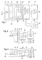
- the circuit arrangement 11 outlined in FIG. 1 of the drawing essentially consists from a switch set 12 in the three motor leads 13 from one frequency converter 15 fed from the household network 14 to an asynchronous motor 16 or similar three-phase motor as a three-phase main drive 17th in a large household appliance, not shown, for example to drive the Drum of a washing machine or the lye circulation pump of a dishwasher.
- a full-wave rectifier 18 in Graetz circuit an essentially consisting of capacitors of large capacity DC intermediate circuit 19 charged. Its output voltage becomes one over alternately switched pairs of switching paths 20 consisting of three parallel half-bridges bridge circuit 21 with changing Polarities and variable durations on the three motor leads 13 Main drive 17 switched.
- the control of the switching processes in the frequency converter 15 via a programmed processor is for ease of overview omitted in the drawing, especially since this measure was successful belongs to the art and is not affected by the present invention.
- the output of the inverter bridge circuit 21 is in the Frequency converter 15 via the motor leads 13 according to the invention arranged switch set 12 with three change-over switches in this example 22 from the three-phase motor 16 of the main drive 17 to one in this Case also three-phase asynchronous or synchronous three-phase motor 23 one Auxiliary drive 24 switched.
- This switchover process becomes the main drive 17 out of operation and the auxiliary drive 24 put into operation, for example to change from the drive of a washing drum to the drive of an emptying pump.
- the motor control of the auxiliary drive 24 takes place to this extent without additional Require circuit measures, such as that of the main drive 17th from the same frequency converter 15, now under the influence of one for operation of the auxiliary drive 24 designed control program for the time sequence the actuation of the switching paths 20.
- additional Require circuit measures such as that of the main drive 17th from the same frequency converter 15, now under the influence of one for operation of the auxiliary drive 24 designed control program for the time sequence the actuation of the switching paths 20.
- the auxiliary drive 24 of the food quantities (voltages.) currently measured on the motor supply lines 13 and currents, or their product as electrical power consumption, in Block diagram not shown separately) on current mechanical or hydraulic Stresses in the fluid system behind the drive 24 are closed and consequently the operation of the auxiliary drive 24 both in terms of influences its power consumption as well as its effect and be optimized in particular.
- the changeover switch set 12 in the motor supply lines 13 consists of only two changeover switches 22 for switching from the main drive 17 to an auxiliary drive 24 here single-phase synchronous or similar three-phase motor 25, which is can also be a capacitor asynchronous motor.
- This auxiliary drive too 24 can, as before the main drive 17, via the behind the intermediate circuit 19 only existing converter bridge circuit 21 with a frequency variable Rotary field can be fed, for example to allow it to start smoothly and then to vary the working speed.
- the switch set 12 has compared to FIG. 2 only a changeover switch 22 on, because now only one of the two motor leads 13 is to be switched from the main drive 17 to the auxiliary drive 24, during its second supply line firmly to a pole of the single-phase mains supply voltage 14 is connected.
- the primary for the control of the main drive 17th designed inverter bridge circuit 21 is also used for control a single phase motor 25; with this minimized topology their reduced switch set 12 is still for voltage and Control of the direction of rotation of the synchronous motor 25 in the auxiliary drive 24 is suitable if who operated in the steady state with the frequency of the household network 14 becomes. Also is the limited speed control of a capacitor asynchronous motor can be realized in the auxiliary drive 24.
- the DC voltage intermediate circuit 19 feeds in the frequency converter 15 parallel to the bridge circuit 21 for the main drive 18, a partial bridge circuit 21 'for a single-phase or three-phase motor 25 or 23 in the auxiliary drive 24.
- the dashed addition expresses that in the case of a three-phase (instead of single-phase) motor 23 of the auxiliary drive 24 in the bridge circuit 21 'after the intermediate circuit 19 then three half bridges the three phases (instead of two half bridges the two motor feed lines 13 a single-phase motor 25) are assigned.
- a topology according to FIG. 5 allows a parallel operation of main and Auxiliary drive motors 16/25 or 16/23 even with different frequencies, with rotating fields rotating at different speeds. condition is only that the sum of the voltage requirements of the two motors 16 + 23/25 the DC voltage at the output of the intermediate circuit 19 does not exceed. Because e.g. the drum main drive 17 of a washing machine over relatively long periods of time fed for a low washing speed with low motor voltage there is sufficient voltage reserve for simultaneous Operation of an auxiliary drive 24 available. Its e.g.
- single phase motor 25 is with one of its two leads 13 to one of the half bridges of the three-phase Bridge circuit 21 connected to the main drive motor 16, and with it second supply line 13 to the only required half bridge of the partial bridge circuit 21 'to the auxiliary drive motor 25.
- a three-phase can also be used as auxiliary drive motor 23 is what then in the partial bridge circuit 21 'another half bridge for the third motor lead 13 is available.
Landscapes
- Engineering & Computer Science (AREA)
- Power Engineering (AREA)
- Control Of Multiple Motors (AREA)
- Control Of Ac Motors In General (AREA)
- Control Of Motors That Do Not Use Commutators (AREA)
Abstract
Description
- Fig. 1
- in den Motorzuleitungen am Ausgang eines Frequenzumrichters eine dreipolige Umschaltung, um vom Betrieb eines Hauptantriebs zum Betrieb eines Hilfsantriebs mit gleichen Steuerungsmöglichkeiten überwechseln zu können,
- Fig. 2
- eine zweipolige Umschaltung zur Inbetriebnahme eines einpoligen Hilfsantriebs,
- Fig. 3
- eine einpolige Umschaltung zur Inbetriebnahme eines einpoligen, mit der speisenden Netzfrequenz drehfeld-synchronen Hilfsantriebs,
- Fig. 4
- einen Parallelbetrieb von dreiphasigem Hauptantrieb und dreiphasigem oder einphasigem Hilfsantrieb mit getrennten Brückenschaltungen hinter einem gemeinsamen Gleichspannungs-Zwischenkreis und
- Fig. 5
- in Abwandlung der zusätzlichen Brückenschaltung nach Fig. 4 eine Möglichkeit zum parallelen Betrieb eines dreiphasigen Hauptantriebs und eines ein- oder dreiphasigen Hilfsantriebs mit unterschiedlichen Drehfeldfrequenzen, unter Einsatz einer Teilbrückenschaltung für einen einphasig an die Brückenschaltung zum Hauptantrieb angeschlossenen Hilfsantrieb.
Claims (8)
- Schaltungsanordnung (11) zum Ansteuern eines aus einem Frequenzumrichter (15) mit gesteuerter Brückenschaltung (21) betriebenen elektromotorischen Hauptantriebs (17) in einem Haushalts-Großgerät, das auch mit einem Hilfsantrieb (24) ausgestattet ist,
dadurch gekennzeichnet, daß der Hilfsantrieb (24) aus demselben Gleichspannungs-Zwischenkreis (19) wie der Hauptantrieb (17) gespeist ist. - Schaltungsanordnung nach Anspruch 1,
dadurch gekennzeichnet, daß die Brückenschaltung (21) über einen Umschaltersatz (12) vom Hauptantrieb (17) auf den Hilfsantrieb (24) umschaltbar ist, woraufhin der Hilfsantrieb (24) aus dem an sich für den Hauptantrieb (17) konzipierten Frequenzumrichter (15) ansteuerbar ist. - Schaltungsanordnung nach Anspruch 2,
dadurch gekennzeichnet, daß der Umschaltersatz (12) in jeder der drei Motorzuleitungen (13) einen Wechselschalter (22) zum Umschalten auf einen dreiphasigen Drehfeld-Motor (23) im Hilfsantrieb (24) aufweist. - Schaltungsanordnung nach Anspruch 2,
dadurch gekennzeichnet, daß der Umschaltersatz (12) zwei Wechselschalter (22) zum Umschalten von Betrieb des Hauptantriebs (17) auf einen Hilfsantrieb (24) mit einphasigem Drehfeldmotor (25) aufweist. - Schaltungsanordnung nach Anspruch 2,
dadurch gekennzeichnet, daß der Umschaltersatz (12) einen Wechselschalter (22) in einer der drei Motorzuleitungen (13) zum Umschalten des Betriebs vom Hauptantrieb (17) auf einen Hilfsantrieb (24) mit einphasigem Motor (25) aufweist, dessen zweite Motorleitung fest an einen Pol des speisenden Netzes (14) vor dem Frequenzumrichter (15) geschaltet ist. - Schaltungsanordnung nach Anspruch 1,
dadurch gekennzeichnet, daß aus dem Gleichspannungs-Zwischenkreis (19) zwei Brückenschaltungen (21,21') parallel gespeist sind, die dem Hauptantrieb (17) bzw. dem Hilfsantrieb (24) zugeordnet sind. - Schaltungsanordnung nach Anspruch 6,
dadurch gekennzeichnet, daß der Hilfsantrieb (24) mit seinem einphasigen oder dreiphasigen Motor (25 bzw. 23) an eine Teilbrückenschaltung (21') mit zwei bzw. drei Halbbrücken angeschlossen ist. - Schaltungsanordnung nach Anspruch 6,
dadurch gekennzeichnet, daß für einen Parallelbetrieb von Haupt- und Hilfsantrieb (17, 24) mit auch unterschiedlichen Drehfeldfrequenzen der Hilfsantrieb (24) mit einem ein- bzw. mit einem dreiphasigen Motor (25 bzw. 23) einphasig an eine Halbbrücke der Brückenschaltung (21) für den Hauptantrieb (17) und mit der anderen Phase bzw. mit den anderen beiden Phasen an die einzige Halbbrücke bzw. an die beiden Halbbrücken einer weiteren, für den Hilfsantrieb (24) parallel dazu betriebenen Brückenschaltung (21') angeschlossen ist; wobei die Motore (16, 23/25) für Haupt- und Hilfsantrieb (17, 24) derart ausgelegt sind, daß die Summe ihrer beiden Motorspannungen die Zwischenkreisspannung am Ausgang des Gleichspannungs-Zwischenkreises (19) nicht übersteigt.
Applications Claiming Priority (2)
| Application Number | Priority Date | Filing Date | Title |
|---|---|---|---|
| DE10207232A DE10207232B4 (de) | 2002-02-21 | 2002-02-21 | Schaltungsanordnung zur Ansteuerung eines elektromotorischen Antriebs, insbesondere Pumpenantriebs, in einem Haushaltgroßgerät |
| DE10207232 | 2002-02-21 |
Publications (2)
| Publication Number | Publication Date |
|---|---|
| EP1341297A2 true EP1341297A2 (de) | 2003-09-03 |
| EP1341297A3 EP1341297A3 (de) | 2005-06-01 |
Family
ID=7713880
Family Applications (1)
| Application Number | Title | Priority Date | Filing Date |
|---|---|---|---|
| EP03003717A Withdrawn EP1341297A3 (de) | 2002-02-21 | 2003-02-19 | Schaltungsanordnung zur Ansteuerung eines elektromotorischen Antriebs, insbesondere Pumpenantriebs, in einem Haushaltsgrossgerät |
Country Status (3)
| Country | Link |
|---|---|
| US (1) | US20030155875A1 (de) |
| EP (1) | EP1341297A3 (de) |
| DE (2) | DE10207232B4 (de) |
Families Citing this family (31)
| Publication number | Priority date | Publication date | Assignee | Title |
|---|---|---|---|---|
| JP4363169B2 (ja) * | 2003-12-11 | 2009-11-11 | パナソニック株式会社 | 食器洗い機のモータ駆動装置 |
| DE102007030072A1 (de) | 2007-06-29 | 2009-01-02 | BSH Bosch und Siemens Hausgeräte GmbH | Elektrischen Antriebseinrichtung für ein Wasserführendes Haushaltsgerät |
| DE102007052232B4 (de) | 2007-10-22 | 2024-08-22 | Fisw Steuerungstechnik Gmbh | Vorrichtung zur Reduzierung des Energiebedarfs von Maschinen |
| DE102008006710A1 (de) * | 2008-01-30 | 2009-08-13 | Siemens Aktiengesellschaft | Stromrichteranordnung mit mehreren unabhängigen Antriebseinheiten |
| EP2254280A1 (de) * | 2009-05-19 | 2010-11-24 | Electrolux Home Products Corporation N.V. | Bussteuerung für ein Haushaltsgerät |
| US8299646B2 (en) * | 2009-07-27 | 2012-10-30 | Rocky Research | HVAC/R system with variable frequency drive (VFD) power supply for multiple motors |
| US8299653B2 (en) * | 2009-07-27 | 2012-10-30 | Rocky Research | HVAC/R system with variable frequency drive power supply for three-phase and single-phase motors |
| US9160258B2 (en) | 2009-07-27 | 2015-10-13 | Rocky Research | Cooling system with increased efficiency |
| EP2309282B1 (de) * | 2009-08-11 | 2019-12-11 | Diehl AKO Stiftung & Co. KG | Verfahren zur Fehlererkennung bei der Ansteuerung eines Drehfeldmotors |
| DE102010042491A1 (de) * | 2010-10-15 | 2012-05-03 | BSH Bosch und Siemens Hausgeräte GmbH | Pumpeneinrichtung für ein Hausgerät, Hausgerät und Verfahren zum Betreiben eines Antriebsmotors |
| CN103233888A (zh) * | 2013-05-14 | 2013-08-07 | 江苏大学 | 一种单变频控制下的多泵切换节能控制系统 |
| US9209721B2 (en) * | 2014-04-29 | 2015-12-08 | The Boeing Company | Systems and methods for the control and operation of a parallel motor controller architecture |
| MX373642B (es) * | 2015-04-20 | 2020-05-04 | Fluid Handling Llc | Dispositivos operados con motor controlado por interruptor. |
| DE102015107934A1 (de) * | 2015-05-20 | 2016-11-24 | Voith Patent Gmbh | Drehzahländerbares Antriebssystem und Verfahren zum Aufstarten und/oder Betreiben eines Drehzahländerbaren Antriebssystems |
| US9979328B1 (en) * | 2016-10-25 | 2018-05-22 | Regal Beloit America, Inc. | Dual-drive electric motor control system and methods for hybrid operation of electric motors |
| WO2021085178A1 (ja) | 2019-11-01 | 2021-05-06 | 株式会社デンソー | 回転機制御装置 |
| WO2021085177A1 (ja) | 2019-11-01 | 2021-05-06 | 株式会社デンソー | 回転機制御装置 |
| JP7211395B2 (ja) | 2020-04-28 | 2023-01-24 | 株式会社デンソー | 回転機制御装置 |
| JP7200976B2 (ja) | 2020-05-12 | 2023-01-10 | 株式会社デンソー | ステアリング制御装置 |
| JP7472745B2 (ja) * | 2020-09-30 | 2024-04-23 | 株式会社デンソー | モータ駆動システム |
| DE102021114707A1 (de) | 2021-06-08 | 2022-12-08 | Minebea Mitsumi Inc. | Steuerschaltung und Verfahren zum Betreiben einer Steuerschaltung |
| DE102021117036A1 (de) | 2021-07-01 | 2023-01-05 | Brose Fahrzeugteile Se & Co. Kommanditgesellschaft, Bamberg | Antriebsanordnung für eine Klappe eines Kraftfahrzeugs |
| DE102021132938A1 (de) | 2021-08-17 | 2023-02-23 | Miele & Cie. Kg | Antriebssystem |
| DE102022110180A1 (de) | 2022-04-27 | 2023-11-02 | Schaeffler Technologies AG & Co. KG | Verfahren zum Pumpenbetrieb, Pumpensteuerung und Kühlungsvorrichtung |
| DE102022117708A1 (de) * | 2022-07-15 | 2024-01-18 | Miele & Cie. Kg | Antriebssystem |
| BE1031041B1 (de) * | 2022-11-15 | 2024-06-10 | Miele & Cie | Antriebssystem |
| BE1032016B1 (de) * | 2023-09-27 | 2025-04-29 | Miele & Cie | Verfahren zur gleichzeitigen Ansteuerung eines dreisträngigen Motors in einem zweiphasigen Betrieb und eines einsträngigen Motors, Motorsteuerung und elektrisches Haushaltsgerät |
| DE102023130529A1 (de) * | 2023-11-06 | 2025-05-08 | Miele & Cie. Kg | Verfahren zum zweiphasigen Betrieb eines dreiphasigen permanenterregten Synchronmotors |
| DE102023133065A1 (de) * | 2023-11-27 | 2025-05-28 | Miele & Cie. Kg | Verfahren zur gleichzeitigen Ansteuerung eines dreisträngigen Motors in einem zweiphasigen Betrieb und eines einsträngigen Motors, Motorsteuerung und elektrisches Haushaltsgerät |
| DE102023135315A1 (de) * | 2023-12-15 | 2025-06-18 | Miele & Cie. Kg | Elektromotoransteuervorrichtung, Elektromotorsystem, und elektrisches Gerät mit dem Elektromotorsystem |
| DE102024102276A1 (de) * | 2024-01-26 | 2025-07-31 | Miele & Cie. Kg | Antriebssystem |
Family Cites Families (10)
| Publication number | Priority date | Publication date | Assignee | Title |
|---|---|---|---|---|
| DE3313167A1 (de) * | 1983-04-12 | 1984-10-25 | Mantec Gesellschaft für Automatisierungs- und Handhabungssysteme mbH, 8510 Fürth | Industrieroboter mit elektrischen drehstrom-einzelantrieben |
| JPS6118391A (ja) * | 1984-07-02 | 1986-01-27 | Nippon Kogaku Kk <Nikon> | 通電方向制御回路 |
| GB8509175D0 (en) * | 1985-02-11 | 1985-05-15 | Breval Sa | Liquefier gas lighter |
| FR2711862B1 (fr) * | 1993-10-25 | 1995-12-01 | Centre Nat Rech Scient | Système d'alimentation de n moteurs asynchrones. |
| JPH1085489A (ja) * | 1996-09-18 | 1998-04-07 | Matsushita Electric Ind Co Ltd | 洗濯機等の制御装置 |
| FR2758668B1 (fr) * | 1997-01-22 | 1999-04-09 | Valeo Electronique | Montage a interrupteurs commandes pour la commande de moteurs electriques |
| US6121749A (en) * | 1998-05-11 | 2000-09-19 | Work Smart Energy Enterprises, Inc. | Variable-speed drive for single-phase motors |
| JP2001129293A (ja) * | 1999-11-09 | 2001-05-15 | Matsushita Electric Ind Co Ltd | 洗濯機の制御装置 |
| JP2001276485A (ja) * | 2000-03-29 | 2001-10-09 | Matsushita Electric Ind Co Ltd | 洗濯機 |
| US6301743B1 (en) * | 2000-08-21 | 2001-10-16 | Matsushita Electric Corporation Of America | Vacuum cleaner with static dissipation circuit |
-
2002
- 2002-02-21 DE DE10207232A patent/DE10207232B4/de not_active Expired - Fee Related
-
2003
- 2003-01-30 US US10/354,650 patent/US20030155875A1/en not_active Abandoned
- 2003-02-18 DE DE20302543U patent/DE20302543U1/de not_active Expired - Lifetime
- 2003-02-19 EP EP03003717A patent/EP1341297A3/de not_active Withdrawn
Also Published As
| Publication number | Publication date |
|---|---|
| DE10207232A1 (de) | 2003-10-02 |
| EP1341297A3 (de) | 2005-06-01 |
| US20030155875A1 (en) | 2003-08-21 |
| DE20302543U1 (de) | 2003-06-12 |
| DE10207232B4 (de) | 2005-11-17 |
Similar Documents
| Publication | Publication Date | Title |
|---|---|---|
| EP1341297A2 (de) | Schaltungsanordnung zur Ansteuerung eines elektromotorischen Antriebs, insbesondere Pumpenantriebs, in einem Haushaltsgrossgerät | |
| DE102014102423A1 (de) | Elektrischer Antrieb mit rekonfigurierbarer Wicklung | |
| DE102010039886B4 (de) | Antriebssystem für ein batteriebetriebenes Fahrzeug | |
| DE1964229A1 (de) | Buerstenloser Gleichstrommotor | |
| EP2186189A2 (de) | Elektrische maschine | |
| EP2646275A1 (de) | Verfahren zum laden einer traktionsbatterie | |
| WO2006103159A1 (de) | Generator mit hoher phasenordnung | |
| EP0215827A1 (de) | Schaltung zur steuerung eines bürstenlosen elektromotors. | |
| EP2744095B1 (de) | Mechatronisches System für elektrisches Gerät | |
| DE2030107A1 (de) | ||
| EP1698032A1 (de) | Verfahren zum betreiben einer umrichterschaltung einer waschmaschine oder eines wäschetrockners | |
| EP1695436B1 (de) | Ansteuerung eines gleichstrommotors | |
| EP3905512B1 (de) | Haushaltsgerät mit einem auf ein wechselspannungsnetz aufschaltbaren motor | |
| WO2012025267A2 (de) | Antriebssystem für ein batteriebetriebenes fahrzeug | |
| EP2266196A2 (de) | Versorgungseinheit für elektrische antriebe und verfahren zur steuerung dieser versorgungseinheit | |
| DE102008007403A1 (de) | Permanentmagneterregte elektrische Maschine für ein Hausgerät | |
| DE102005052991A1 (de) | Verfahren und Schaltungsanordnung zur Steuerung des Betriebs eines Elektromotors eines elektrischen Gerätes, insbesondere eines elektrischen Hausgerätes, sowie dabei einsetzbare Schnittstellenschaltungsanordnung | |
| DE102019210786A1 (de) | System | |
| AT245692B (de) | Drehzahlgesteuerter Stromrichtermotor | |
| DE830977C (de) | Ein- und mehrphasige Frequenz- und Phasenwandlergruppe | |
| DE3036194A1 (de) | Elektrischer zweimotorenantrieb, insbesondere waschautomatenantrieb | |
| AT383916B (de) | Gleichstrommotor mit permanentmagnetischem rotor und elektronischer kommutierschaltung | |
| DE10021918B4 (de) | System zum Ansteuern von Wechselstrom-Motoren | |
| DE1538178C (de) | Schalt-Anordnung zum Zu- und Abschalten eines Anlaßstromkreises für einen Einphasenwechsels trom-Induktionsmotor | |
| DE574575C (de) | Einrichtung zum Betrieb von zwei oder mehreren mechanisch gekuppelten Einphasenmotoren |
Legal Events
| Date | Code | Title | Description |
|---|---|---|---|
| PUAI | Public reference made under article 153(3) epc to a published international application that has entered the european phase |
Free format text: ORIGINAL CODE: 0009012 |
|
| AK | Designated contracting states |
Kind code of ref document: A2 Designated state(s): AT BE BG CH CY CZ DE DK EE ES FI FR GB GR HU IE IT LI LU MC NL PT SE SI SK TR |
|
| AX | Request for extension of the european patent |
Extension state: AL LT LV MK RO |
|
| PUAL | Search report despatched |
Free format text: ORIGINAL CODE: 0009013 |
|
| AK | Designated contracting states |
Kind code of ref document: A3 Designated state(s): AT BE BG CH CY CZ DE DK EE ES FI FR GB GR HU IE IT LI LU MC NL PT SE SI SK TR |
|
| AX | Request for extension of the european patent |
Extension state: AL LT LV MK RO |
|
| RIC1 | Information provided on ipc code assigned before grant |
Ipc: 7D 06F 33/02 B Ipc: 7H 02P 5/46 A |
|
| 17P | Request for examination filed |
Effective date: 20050604 |
|
| AKX | Designation fees paid |
Designated state(s): AT BE BG CH CY CZ DE DK EE ES FI FR GB GR HU IE IT LI LU MC NL PT SE SI SK TR |
|
| GRAP | Despatch of communication of intention to grant a patent |
Free format text: ORIGINAL CODE: EPIDOSNIGR1 |
|
| STAA | Information on the status of an ep patent application or granted ep patent |
Free format text: STATUS: THE APPLICATION IS DEEMED TO BE WITHDRAWN |
|
| 18D | Application deemed to be withdrawn |
Effective date: 20071127 |