EP1341069B1 - Regulateur de debit et soupape avec un regulateur de debit - Google Patents
Regulateur de debit et soupape avec un regulateur de debit Download PDFInfo
- Publication number
- EP1341069B1 EP1341069B1 EP03002808A EP03002808A EP1341069B1 EP 1341069 B1 EP1341069 B1 EP 1341069B1 EP 03002808 A EP03002808 A EP 03002808A EP 03002808 A EP03002808 A EP 03002808A EP 1341069 B1 EP1341069 B1 EP 1341069B1
- Authority
- EP
- European Patent Office
- Prior art keywords
- control element
- flow controller
- section
- valve
- flow
- Prior art date
- Legal status (The legal status is an assumption and is not a legal conclusion. Google has not performed a legal analysis and makes no representation as to the accuracy of the status listed.)
- Expired - Lifetime
Links
- 239000012530 fluid Substances 0.000 claims abstract description 21
- 230000002093 peripheral effect Effects 0.000 claims abstract description 4
- 238000007789 sealing Methods 0.000 claims description 11
- 230000007423 decrease Effects 0.000 claims description 4
- 229920003023 plastic Polymers 0.000 claims description 3
- 239000004033 plastic Substances 0.000 claims description 3
- 238000011144 upstream manufacturing Methods 0.000 claims description 2
- 230000006835 compression Effects 0.000 description 7
- 238000007906 compression Methods 0.000 description 7
- 239000000243 solution Substances 0.000 description 5
- 238000004519 manufacturing process Methods 0.000 description 4
- 238000006073 displacement reaction Methods 0.000 description 2
- 238000005553 drilling Methods 0.000 description 2
- 238000012423 maintenance Methods 0.000 description 2
- 239000002245 particle Substances 0.000 description 2
- 230000033228 biological regulation Effects 0.000 description 1
- 238000010276 construction Methods 0.000 description 1
- 230000003247 decreasing effect Effects 0.000 description 1
- 230000001419 dependent effect Effects 0.000 description 1
- 238000011161 development Methods 0.000 description 1
- 230000018109 developmental process Effects 0.000 description 1
- 210000003746 feather Anatomy 0.000 description 1
- 238000002347 injection Methods 0.000 description 1
- 239000007924 injection Substances 0.000 description 1
- 239000000463 material Substances 0.000 description 1
- 239000002184 metal Substances 0.000 description 1
- 238000004080 punching Methods 0.000 description 1
- 230000001105 regulatory effect Effects 0.000 description 1
- 239000007921 spray Substances 0.000 description 1
- XLYOFNOQVPJJNP-UHFFFAOYSA-N water Substances O XLYOFNOQVPJJNP-UHFFFAOYSA-N 0.000 description 1
Images

Classifications
-
- G—PHYSICS
- G05—CONTROLLING; REGULATING
- G05D—SYSTEMS FOR CONTROLLING OR REGULATING NON-ELECTRIC VARIABLES
- G05D7/00—Control of flow
- G05D7/01—Control of flow without auxiliary power
- G05D7/0126—Control of flow without auxiliary power the sensing element being a piston or plunger associated with one or more springs
- G05D7/0133—Control of flow without auxiliary power the sensing element being a piston or plunger associated with one or more springs within the flow-path
Definitions
- the present invention relates to a flow regulator comprising a fixed casing part, which is traversed by a fluid substantially in the axial direction and an axially displaceable within the casing member against a spring force control element, wherein the cross section of flow openings through the flow controller varies depending on the respective position of the control element ,
- the invention further relates to a thermostatic valve, in whose housing a flow regulator of the aforementioned type is used, wherein the control element has a closed peripheral surface, and the shell part in the portion within which the control element is displaceable, having a varying inner cross-section, so that the available Reduced flow cross-section for the fluid between the outer periphery of the control element and the inner cross section of the shell portion upon inward movement of the control element.
- Flow regulators of the type mentioned are known from the prior art.
- DE 2 258 787 A1 describes a flow regulator in which various holes are provided in the peripheral region of the control element, whereas the inner cross section of the shell part, within which the control element shifts in the axial direction, is constant.
- the flow takes place through passage openings in cylindrical surfaces of the control element, these passage openings tapering, for example in the axial displacement direction of the control element, so that it is achieved that within a range with changing pressure, the flow through the arrangement of control element and shell part remains substantially constant.
- the control element is a part of sheet metal a relatively thin wall, so that the provision of the specific passage openings z. B. by punching and thus the production of this component is technically complex and difficult.
- the PCT publication WO 91/10949 describes a flow regulator in which the control element is a ball which is axially displaceable against a spring force within a bore of a shell part.
- the control element is a ball which is axially displaceable against a spring force within a bore of a shell part.
- the bore of the shell part At the periphery of the bore of the shell part there are two axially parallel grooves, which have different lengths. The fluid flows past the circumference of the control element through these grooves. Although the fluid flows in the axial direction into the bore of the jacket part, but leaves it over a relatively small radial bore. This radial bore is located at the level of the end of an axially parallel circumferential groove.
- the grooves have no control function, in the sense that the flow cross section through the grooves in the movement of the control element changes, but the grooves serve as a bypass over the control element formed as a ball.
- the regulation takes place via the transverse to the flow direction aligned outlet opening. It builds up a differential pressure in front of and behind the ball. The fluid first flows into the space behind the ball and then back through the radial outlet. By this arrangement, it will lead to turbulence, which is expected to increase flow noise.
- the publication with the publication number DE 200 22 166 U1 discloses a flow regulator of the aforementioned type.
- the flow-through cross section in a lower position of the control element is essentially determined by the position of the control element relative to a valve seat. Once a certain position has been reached, however, the flow-through cross-section remains unchanged, even if the control element continues is moved. As a result, even with a further displacement of the regulating element no larger volume flow can be achieved.
- the object of the present invention is to provide a flow regulator of the type mentioned above, which, while retaining the stated properties with regard to the flow characteristic, enables simpler production and thus provides a sensible alternative.
- the object of the invention is also to provide a valve which comprises a flow regulator with the mentioned properties, besides providing further functions of a thermostatic valve and thereby has a simple space-saving design.
- the solution to this problem provides a thermostatic valve, in whose housing a flow regulator of the aforementioned type according to the invention is used, according to the features of claim 15.
- the openings for flow control are not in the control element, which moves in the shell element, but in the non-movable shell element.
- the flow characteristic results from a varying internal cross-section of the shell part, whereby one achieves that the available flow area for the fluid, which results between the outer circumference of the control element and the inner cross section of the shell portion, with varying differential pressure and thus inward movement of the control element reduces the flow regulator over a certain varying differential pressure range a substantially constant Volume flow delivers.
- the varying inner cross section results from at least one on the inner circumference of the shell portion existing substantially in the axial direction extending or groove-shaped bulge whose cross-section is reduced in the inward direction (relative to the direction of movement of the control element).
- This groove or groove-shaped bulge of the shell part for example, in the axial direction, at least in sections, have an approximately parabolic contour, ie, the available cross-section through this groove preferably does not change in sections in a linear manner.
- the control element preferably moves within a cylindrical or slightly conical bore of the shell part.
- the control element is preferably dimensioned in its diameter so that it is dimensionally largely suitable in the bore of the jacket part is guided.
- This control element may for example be cylindrical or at least partially cylindrical in its basic form.
- control element substantially fills the diameter of said bore, so that the flow cross-section is defined by the then remaining free space, which results from the grooves. Unwanted secondary currents between the control element and the jacket part are therefore preferably to be avoided.
- the control element provided at its periphery with at least one sealing element such as a sealing lip, which seals to the inner wall of the bore. There then remains a well-defined clearance for the flow of the fluid, which is determined by the cross section of the groove or grooves.
- the control element for example, plastic
- the use of a control element which is for example a plastic injection molded part, has the advantage of accurate and cost-effective production, especially in the production of larger series.
- the maximum stroke position of the control element is preferably defined by a shoulder at the end of the bore of the shell part, which serves as a stop.
- the solution according to the invention with a groove or grooves in the shell part also has the further advantage that, in the case of different flow regulators, which are provided for different flow rates, a control element that is in principle the same is used can, wherein only the number of grooves in the shell part varies. With the rest of the same design, for example, by providing two grooves with the same cross-section and the same variable cross-sectional characteristics at the same trained control element can create a flow regulator with double flow.
- a series of different flow regulators with different volume flows is required, which can be provided according to the invention by introducing only one groove into the shell part at the smallest desired volume flow, so that the volume flow is then achieved by two, three, four or more grooves can multiply, without other changes in the design of the flow controller are necessary. This reduces the total number of parts required for such a series of flow regulators with different volume flows.
- the invention further relates to a thermostatic valve, in whose housing a flow regulator of the type mentioned is used.
- a thermostatic valve preferably performs other functions, in particular, this has a spring-loaded Huboberteil with valve stem and plug on which a valve seat is assigned in the housing, so that you can open or close the valve automatically.
- a manually operable valve head with closure body is also possible for a manual opening or closing of the valve.
- a strainer upstream of the flow regulator in the interior of the housing of the thermostatic valve can be, for example, a wire screen or the like.
- a thermostatic valve of the type mentioned has according to an embodiment of the invention, a first radially outgoing inlet nozzle and preferably arranged with an axial offset to the inlet nozzle also radially outgoing outlet nozzle.
- Particularly advantageous is a design of the type mentioned in the so-called Doppeleckaus Office, since it has the advantage of a low overall height, because all housing openings are in one plane.
- the small overall length is advantageous, which is defined by the longest component, which in this case is the flow regulator insert.
- the connections in the region of the inlet nozzle and the outlet nozzle are parallel to each other and extend to opposite sides of the housing. The number of housing openings is inventively minimized and the housing shape is particularly streamlined for a low flow resistance.
- the said spring-loaded Huboberteil or the manually operable valve upper part may be arranged in axial extension to a central part of the housing, wherein the central part receives the flow regulator and the axis of the outlet nozzle is preferably arranged at right angles to the axis of the lifting movement of the closure piece. If one provides a further neck on the housing, which is preferably arranged at the opposite end to the spring-loaded Huboberteil and which can be closed, for example, a screw-in closure piece, one can create there access to the housing interior, especially for maintenance purposes, for example, to exchange said strainer. Also, this further nozzle and the nozzle for the spring-loaded Huboberteil lies here preferably in the same plane as inlet nozzle and outlet nozzle.
- FIG. 1 shows a flow regulator according to the invention which comprises a casing part 1, which in principle has a sleeve-like, partially cylindrical and tubular basic shape.
- This shell part 1 has in an upper portion of a cylindrical bore 2, within which a control element 5 can move axially displaceable.
- Figure 1 shows this control element 5 in the right half of the drawing in an upper position and it can be seen that below the Control element 5 a compression spring 4 is located.
- the arrow above the sectional view shows the direction of flow through the flow controller according to the invention.
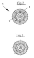
- grooves 3 running in the axial direction in the longitudinal direction, in the region of the inside of the shell part 1, several such grooves 3 being distributed over the inner circumference of the shell part are arranged, for example, eight such grooves as seen in Figure 2. These grooves 3 extend through the entire length of the wall of the shell part 1, but are open in the lower half of the shell part to the outside, so that slots 3a result, through which the water can escape radially outward, as shown in FIG can take.
- the depth of the groove 3 is not constant, but in the upper region and in the region of the bore 2, within which the control element 5 can move, the groove depth 3 decreases to the paragraph 11, wherein in the section of the wall, which is shown in Figure 1 on the left, and extending in the bore 2 to the paragraph 11, an approximately parabolic contour of the wall of the shell part 1 with further inwardly decreasing groove depth results.
- the control element 5 has, as can be seen from Figure 1 and Figure 6, a closed bottom, so that it covers the entire bore 2 of the shell part and the flow of fluid can be done only laterally through the grooves 3, whereas on, for example, molded sealing lips. 6 , which are preferably mounted on the front side and back on the circumference of the control element 5 (see Figure 6), the control element to the inner wall of the bore 2 of the shell part 1 seals off, so that there is a side stream of fluid is prevented. As a result, the volume flow is defined by the cross section of the groove 3 and the grooves.
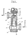
- valve has a spring-loaded lift top 23, with a valve stem 22 having at the front end a closure body 31 which is movable against a valve seat 32 in the housing to close the passage of the fluid through the valve.
- valve spindle 22 for example, is electrically driven, wherein on the valve spindle 22, a sleeve 34 is seated, which is acted upon by a prestressed spring 35, so that the closing of the closure piece 31 against the force of Spring 35 is done.
- the flow regulator 1 also has on the outside a preferably molded sealing lip 38, whereby a seal is provided to the housing.
- the valve further comprises a housing having a substantially cylindrical central portion 27, from the bottom of a first inlet port 26 radially passes, through which the fluid passes into the housing interior, then it flows through the flow regulator with the control element 5, here different as in the variant described above is a ball, wherein the flow regulator is shown in Figure 4 in a relation to Figure 1 rotated by 180 ° position corresponding to the flow direction of the fluid.
- the valve housing further comprises a likewise radially outgoing outlet nozzle 28 in the upper region below the upper valve part 23, so that the outlet nozzle 28 parallel but with axial offset to the inlet nozzle 26 goes from the cylindrical middle part 27. It is therefore in principle a so-called Doppeleckan extract with Double angular misalignment in the flow direction, which makes it possible to build the housing of the thermostatic valve in total particularly flat, since the existing nozzles are all in one plane.
- the end is arranged in the axial extension of the middle part 27 and a middle at the other end opposite short stub 33, which receives the valve top 23 , which can be screwed for example in the socket.
- an annular strainer 21 which consists of a wire mesh or a similar sieve-like material can exist in the area between the housing middle part 27 and the lower end-side nozzle 24, which is closed by a screw-cap 25, is located in axial extension to the casing part 1 with the control element 5, an annular strainer 21, which consists of a wire mesh or a similar sieve-like material can exist.
- the strainer 21 is approximately equal to the Materialsssstutzens 26 of the housing arranged so that the inflowing fluid flows through the strainer 21 and in particular coarser particles are held by this, so that they can not get into the region of the control element 5 and affect its mobility.
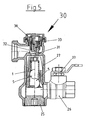
- FIG. 5 shows an alternative variant of the invention, in which the valve is basically constructed in the housing parts as well as the previously described valve according to FIG 4. Also in the valve according to Figure 5, the jacket part 1 with the control element 5 in the cylindrical middle part 27 used. Unlike the thermostat valve variant described above, in the variant according to FIG. 5, a manually operable valve top 30 is inserted into the socket 33, so that the valve is opened by actuation of the closure body 31, which in turn is assigned a valve seat 32 of the housing or can close.
- the flow direction and the function of the flow controller with the control element 5 otherwise corresponds to the embodiment described above with reference to FIG 4. By unscrewing the closure piece 25, the interior of the valve housing for the service is accessible and it can, for example, the flow regulator 1, 5 are replaced.
- the manually operable valve body 30 is accessible.
- an operable ball valve 37 is here still in the area of the inlet nozzle 26 arranged so that you can shut off here, if the valve z. B. should be opened for maintenance from below.
Landscapes
- Physics & Mathematics (AREA)
- General Physics & Mathematics (AREA)
- Engineering & Computer Science (AREA)
- Automation & Control Theory (AREA)
- Lift Valve (AREA)
- Steering Control In Accordance With Driving Conditions (AREA)
- Flow Control (AREA)
- Temperature-Responsive Valves (AREA)
Claims (21)
- Régulateur de débit comprenant une partie d'enveloppe fixe (1), qui est parcourue essentiellement dans la direction axiale par un fluide et un élément de régulation (5) déplaçable axialement à l'intérieur de la partie d'enveloppe (1) à l'encontre d'une force de ressort, la section transversale d'ouvertures de passage à travers le régulateur de débit variant en fonction de la position respective de l'élément de régulation (5), l'élément de régulation (5) présentant une surface périphérique fermée et la partie d'enveloppe (1) présentant, dans la portion à l'intérieur de laquelle l'élément de régulation (5) peut être déplacé, une section transversale interne variable, de sorte que la section transversale de passage disponible pour le fluide entre la périphérie extérieure de l'élément de régulation (5) et la section transversale interne de la partie d'enveloppe (1) diminue lors du déplacement vers l'intérieur de l'élément de régulation,
caractérisé en ce que
la partie d'enveloppe (1) présente, sur la périphérie interne au moins une rainure s'étendant essentiellement dans la direction axiale, ou une indentation en forme de rainure (3), dont la section transversale diminue dans la direction allant vers l'intérieur. - Régulateur de débit selon la revendication 1, caractérisé en ce que la rainure ou l'indentation en forme de rainure (3) de la partie d'enveloppe (1) présente en coupe longitudinale, vu dans la direction axiale, au moins en partie un contour parabolique.
- Régulateur de débit selon la revendication 1 ou 2, caractérisé en ce que la partie d'enveloppe (1) présente un alésage (2) cylindrique ou légèrement conique, à l'intérieur duquel se déplace l'élément de régulation (5).
- Régulateur de débit selon l'une quelconque des revendications 1 à 3, caractérisé en ce que l'élément de régulation (5) est dimensionné de telle sorte en diamètre qu'il est guidé de manière à s'adapter du point de vue dimensionnel dans l'alésage (2) de la partie d'enveloppe (1).
- Régulateur de débit selon l'une quelconque des revendications 1 à 4, caractérisé en ce que l'élément de régulation (5) présente sur sa périphérie au moins un élément d'étanchéité, de préférence une lèvre d'étanchéité (6), qui réalise l'étanchéité vis-à-vis de la paroi interne de l'alésage (2) et/ou la partie d'enveloppe (1) présente sur la périphérie une lèvre d'étanchéité (38) de préférence façonnée.
- Régulateur de débit selon l'une quelconque des revendications 1 à 5, caractérisé en ce que l'élément de régulation présente à chaque fois dans les deux parties d'extrémité un élément d'étanchéité (6) réalisant l'étanchéité vis-à-vis de l'alésage (2), de préférence une lèvre d'étanchéité moulée par injection.
- Régulateur de débit selon l'une quelconque des revendications 1 à 6, caractérisé en ce que l'élément de régulation (5) présente essentiellement la forme d'un cylindre ou d'une sphère.
- Régulateur de débit selon l'une quelconque des revendications 1 à 7, caractérisé en ce que la section transversale interne de la partie d'enveloppe (1) variant dans la direction axiale est dimensionnée de telle sorte que lors de la levée axiale de l'élément de régulation (5), et de la variation de la pression différentielle sur une plage de pression prédéfinie, un débit volumique constant du fluide est obtenu à travers le régulateur de débit.
- Régulateur de débit selon l'une quelconque des revendications 1 à 8, caractérisé en ce que l'élément de régulation (5) est une pièce moulée par injection de plastique.
- Régulateur de débit selon l'une quelconque des revendications 1 à 9, caractérisé en ce qu'au moins une rainure ou une indentation en forme de rainure (3) s'étend sur toute la longueur de la partie d'enveloppe (1).
- Régulateur de débit selon l'une quelconque des revendications 1 à 10, caractérisé en ce qu'un épaulement (11) à l'extrémité de l'alésage (2) constitue une butée pour l'élément de régulation (5) dans sa position de levée maximale.
- Régulateur de débit selon l'une quelconque des revendications 1 à 11, caractérisé en ce que la section transversale de la rainure ou de l'indentation en forme de rainure (3) dans la paroi de la partie d'enveloppe (1) diminue dans la direction axiale approximativement jusqu'à l'épaulement (11).
- Régulateur de débit selon l'une quelconque des revendications 1 à 12, caractérisé en ce que la section transversale de la rainure (3) diminue de manière non linéaire dans la direction axiale dans la paroi de la partie d'enveloppe (1).
- Soupape thermostatique, caractérisée en ce qu'un régulateur de débit selon l'une quelconque des revendications 1 à 13 est inséré dans son boîtier.
- Soupape thermostatique selon la revendication 14, caractérisée en ce qu'elle présente une partie supérieure de levage sollicitée par ressort avec une tige de soupape et une pièce de fermeture, à laquelle est associé un siège de soupape dans le boîtier, pour une ouverture et une fermeture automatiques de la soupape.
- Soupape thermostatique selon la revendication 14, caractérisée en ce qu'elle présente une partie supérieure de soupape (30) actionnable manuellement, avec un corps de fermeture (31), auquel est associé un siège de soupape (32) dans le boîtier, pour une ouverture et une fermeture manuelles de la soupape.
- Soupape thermostatique selon l'une quelconque des revendications 14 à 16, caractérisée en ce qu'elle présente un piège à poussière (21) disposé à l'intérieur du boîtier et monté en amont du régulateur de débit dans lé sens de l'écoulement, de préférence sous la forme d'un tamis métallique.
- Soupape thermostatique, de préférence selon l'une quelconque des revendications 14 à 17, caractérisée en ce qu'elle présente un premier raccord d'entrée (26) saillant radialement, une partie centrale de boîtier (27) essentiellement cylindrique et un raccord de sortie (28) saillant également radialement, décalé axialement par rapport au raccord d'entrée (26).
- Soupape thermostatique selon l'une quelconque des revendications 14 à 18, caractérisée en ce que la partie supérieure de levage (23) sollicitée par ressort ou la partie supérieure de soupape à actionnement manuel est disposée dans le prolongement axial de la partie centrale (27) du boîtier, et l'axe du raccord de sortie (28) est disposé à angle droit par rapport à l'axe du mouvement de levage de la pièce de fermeture (31).
- Soupape thermostatique selon l'une quelconque des revendications 14 à 19, caractérisée en ce que le boîtier présente un autre raccord (24) qui peut être fermé par une pièce de fermeture (25) de préférence vissable, et par le biais duquel l'intérieur du boîtier est accessible.
- Soupape thermostatique selon l'une quelconque des revendications 14 à 20, caractérisée en ce que le raccord (24) est disposé en regard d'un raccord (33) recevant la partie supérieure de la soupape (23), dans le prolongement axial au niveau de l'autre extrémité du boîtier.
Applications Claiming Priority (2)
| Application Number | Priority Date | Filing Date | Title |
|---|---|---|---|
| DE10205406A DE10205406A1 (de) | 2002-02-09 | 2002-02-09 | Durchflussmengenregler und Ventil mit Durchflussmengenregler |
| DE10205406 | 2002-02-09 |
Publications (2)
| Publication Number | Publication Date |
|---|---|
| EP1341069A1 EP1341069A1 (fr) | 2003-09-03 |
| EP1341069B1 true EP1341069B1 (fr) | 2006-08-23 |
Family
ID=27618505
Family Applications (1)
| Application Number | Title | Priority Date | Filing Date |
|---|---|---|---|
| EP03002808A Expired - Lifetime EP1341069B1 (fr) | 2002-02-09 | 2003-02-07 | Regulateur de debit et soupape avec un regulateur de debit |
Country Status (4)
| Country | Link |
|---|---|
| EP (1) | EP1341069B1 (fr) |
| AT (1) | ATE337577T1 (fr) |
| DE (2) | DE10205406A1 (fr) |
| DK (1) | DK1341069T3 (fr) |
Family Cites Families (10)
| Publication number | Priority date | Publication date | Assignee | Title |
|---|---|---|---|---|
| US3015341A (en) * | 1958-01-10 | 1962-01-02 | William Waterman | Flow regulators |
| US3093155A (en) * | 1960-06-20 | 1963-06-11 | Bendix Corp | Variable-restriction valve |
| DE1473034A1 (de) * | 1964-08-11 | 1968-11-07 | Benkisser Werk Kg | Durchflussmengenregler |
| US4306585A (en) * | 1979-10-03 | 1981-12-22 | Manos William S | Constant flow valve |
| JPS5790470A (en) * | 1980-11-26 | 1982-06-05 | Sotokazu Rikuta | Constant flow valve |
| DE3310007A1 (de) * | 1983-03-19 | 1984-09-20 | Schlösser GmbH, 5960 Olpe | Thermostatgesteuertes dreiwege-regulierventil, insbesondere fuer einrohr-heizungsanlagen |
| AU7183991A (en) * | 1990-01-08 | 1991-08-05 | Alco Standard Corporation | Fluid flow regulator |
| US5383489A (en) * | 1993-10-26 | 1995-01-24 | Flow Design, Inc. | Flow control valve with enhanced flow control piston |
| GB2370096A (en) * | 2000-12-18 | 2002-06-19 | Fluid Controls U K Ltd | Constant flow control valve |
| DE20022166U1 (de) * | 2000-12-20 | 2001-06-21 | Huthmann, André, 27632 Midlum | Vorrichtung zum Regeln der Durchflußmenge eines fluiden Mediums |
-
2002
- 2002-02-09 DE DE10205406A patent/DE10205406A1/de not_active Withdrawn
-
2003
- 2003-02-07 EP EP03002808A patent/EP1341069B1/fr not_active Expired - Lifetime
- 2003-02-07 DK DK03002808T patent/DK1341069T3/da active
- 2003-02-07 AT AT03002808T patent/ATE337577T1/de active
- 2003-02-07 DE DE50304698T patent/DE50304698D1/de not_active Expired - Lifetime
Also Published As
| Publication number | Publication date |
|---|---|
| DK1341069T3 (da) | 2007-01-02 |
| EP1341069A1 (fr) | 2003-09-03 |
| DE10205406A1 (de) | 2003-08-21 |
| DE50304698D1 (de) | 2006-10-05 |
| ATE337577T1 (de) | 2006-09-15 |
Similar Documents
| Publication | Publication Date | Title |
|---|---|---|
| DE10325846B4 (de) | Druckmindernder Regler | |
| DE3150100C2 (de) | Schwimmergesteuertes Wasserzulaufventil | |
| DE69409249T2 (de) | Hubventil mit externer einstellung eines durchflussbegrenzers | |
| DE1295938B (de) | Niederschraubventil, insbesondere Drosselventil | |
| DE69217946T2 (de) | Rückführventil | |
| EP1516237B1 (fr) | Regulateur de debit | |
| EP0731230A2 (fr) | Soupape de remplissage pour réservoir de chasse d'eau | |
| DE2608791C2 (fr) | ||
| EP3362713B1 (fr) | Soupape-champignon | |
| DE4402752A1 (de) | Heizkörperventil | |
| EP1341069B1 (fr) | Regulateur de debit et soupape avec un regulateur de debit | |
| DE69516282T2 (de) | Vorrichtung zur regelung des druckes und der strömung in kühl-oder heizanlagen | |
| DE19944364A1 (de) | Einbauventil für einen Gliederheizkörper | |
| DE4407447A1 (de) | Voreinstellbares Regulierventil | |
| DE10132001C2 (de) | Thermostatischer Regler zur Regelung der Durchflussmenge eines Fluids | |
| DE10156500C5 (de) | Druckminderungsventil | |
| DE3231222A1 (de) | Ventil | |
| DE102005011947B3 (de) | Durchflussmengenregler | |
| DE102007025823B4 (de) | Einbauventil, insbesondere für einen Gliederheizkörper, und Gliederheizkörper | |
| DE112021002592T5 (de) | Thermostatische Anordnung, insbesondere thermostatische Patrone | |
| DE2050025B2 (de) | Eingriff Mischbatterie | |
| DE102006039730B3 (de) | Einbauventil | |
| DE202021100188U1 (de) | Sanitäre Baugruppe zur Erzeugung eines zeitlich variierenden Wasserstrahls | |
| DE69212031T2 (de) | Pneumatisches Verbindungssystem mit einem verbesserten Luftregelventil | |
| DE102013203570A1 (de) | Schraubanordnung |
Legal Events
| Date | Code | Title | Description |
|---|---|---|---|
| PUAI | Public reference made under article 153(3) epc to a published international application that has entered the european phase |
Free format text: ORIGINAL CODE: 0009012 |
|
| 17P | Request for examination filed |
Effective date: 20030628 |
|
| AK | Designated contracting states |
Kind code of ref document: A1 Designated state(s): AT BE BG CH CY CZ DE DK EE ES FI FR GB GR HU IE IT LI LU MC NL PT SE SI SK TR |
|
| AX | Request for extension of the european patent |
Extension state: AL LT LV MK RO |
|
| AKX | Designation fees paid |
Designated state(s): AT BE BG CH CY CZ DE DK EE ES FI FR GB GR HU IE IT LI LU MC NL PT SE SI SK TR |
|
| RAP1 | Party data changed (applicant data changed or rights of an application transferred) |
Owner name: HONEYWELL TECHNOLOGIES SARL |
|
| GRAP | Despatch of communication of intention to grant a patent |
Free format text: ORIGINAL CODE: EPIDOSNIGR1 |
|
| GRAS | Grant fee paid |
Free format text: ORIGINAL CODE: EPIDOSNIGR3 |
|
| GRAA | (expected) grant |
Free format text: ORIGINAL CODE: 0009210 |
|
| AK | Designated contracting states |
Kind code of ref document: B1 Designated state(s): AT BE BG CH CY CZ DE DK EE ES FI FR GB GR HU IE IT LI LU MC NL PT SE SI SK TR |
|
| PG25 | Lapsed in a contracting state [announced via postgrant information from national office to epo] |
Ref country code: FI Free format text: LAPSE BECAUSE OF FAILURE TO SUBMIT A TRANSLATION OF THE DESCRIPTION OR TO PAY THE FEE WITHIN THE PRESCRIBED TIME-LIMIT Effective date: 20060823 Ref country code: SK Free format text: LAPSE BECAUSE OF FAILURE TO SUBMIT A TRANSLATION OF THE DESCRIPTION OR TO PAY THE FEE WITHIN THE PRESCRIBED TIME-LIMIT Effective date: 20060823 Ref country code: IE Free format text: LAPSE BECAUSE OF FAILURE TO SUBMIT A TRANSLATION OF THE DESCRIPTION OR TO PAY THE FEE WITHIN THE PRESCRIBED TIME-LIMIT Effective date: 20060823 Ref country code: SI Free format text: LAPSE BECAUSE OF FAILURE TO SUBMIT A TRANSLATION OF THE DESCRIPTION OR TO PAY THE FEE WITHIN THE PRESCRIBED TIME-LIMIT Effective date: 20060823 Ref country code: IT Free format text: LAPSE BECAUSE OF FAILURE TO SUBMIT A TRANSLATION OF THE DESCRIPTION OR TO PAY THE FEE WITHIN THE PRESCRIBED TIME-LIMIT;WARNING: LAPSES OF ITALIAN PATENTS WITH EFFECTIVE DATE BEFORE 2007 MAY HAVE OCCURRED AT ANY TIME BEFORE 2007. THE CORRECT EFFECTIVE DATE MAY BE DIFFERENT FROM THE ONE RECORDED. Effective date: 20060823 |
|
| REG | Reference to a national code |
Ref country code: GB Ref legal event code: FG4D Free format text: NOT ENGLISH |
|
| REG | Reference to a national code |
Ref country code: CH Ref legal event code: EP |
|
| REG | Reference to a national code |
Ref country code: IE Ref legal event code: FG4D Free format text: LANGUAGE OF EP DOCUMENT: GERMAN |
|
| REF | Corresponds to: |
Ref document number: 50304698 Country of ref document: DE Date of ref document: 20061005 Kind code of ref document: P |
|
| PG25 | Lapsed in a contracting state [announced via postgrant information from national office to epo] |
Ref country code: BG Free format text: LAPSE BECAUSE OF FAILURE TO SUBMIT A TRANSLATION OF THE DESCRIPTION OR TO PAY THE FEE WITHIN THE PRESCRIBED TIME-LIMIT Effective date: 20061123 |
|
| REG | Reference to a national code |
Ref country code: SE Ref legal event code: TRGR |
|
| PG25 | Lapsed in a contracting state [announced via postgrant information from national office to epo] |
Ref country code: ES Free format text: LAPSE BECAUSE OF FAILURE TO SUBMIT A TRANSLATION OF THE DESCRIPTION OR TO PAY THE FEE WITHIN THE PRESCRIBED TIME-LIMIT Effective date: 20061204 |
|
| GBT | Gb: translation of ep patent filed (gb section 77(6)(a)/1977) |
Effective date: 20061115 |
|
| REG | Reference to a national code |
Ref country code: DK Ref legal event code: T3 |
|
| PG25 | Lapsed in a contracting state [announced via postgrant information from national office to epo] |
Ref country code: PT Free format text: LAPSE BECAUSE OF FAILURE TO SUBMIT A TRANSLATION OF THE DESCRIPTION OR TO PAY THE FEE WITHIN THE PRESCRIBED TIME-LIMIT Effective date: 20070124 |
|
| PG25 | Lapsed in a contracting state [announced via postgrant information from national office to epo] |
Ref country code: MC Free format text: LAPSE BECAUSE OF NON-PAYMENT OF DUE FEES Effective date: 20070228 |
|
| REG | Reference to a national code |
Ref country code: IE Ref legal event code: FD4D |
|
| ET | Fr: translation filed | ||
| PLBE | No opposition filed within time limit |
Free format text: ORIGINAL CODE: 0009261 |
|
| STAA | Information on the status of an ep patent application or granted ep patent |
Free format text: STATUS: NO OPPOSITION FILED WITHIN TIME LIMIT |
|
| 26N | No opposition filed |
Effective date: 20070524 |
|
| BERE | Be: lapsed |
Owner name: HONEYWELL TECHNOLOGIES SARL Effective date: 20070228 |
|
| PG25 | Lapsed in a contracting state [announced via postgrant information from national office to epo] |
Ref country code: BE Free format text: LAPSE BECAUSE OF NON-PAYMENT OF DUE FEES Effective date: 20070228 |
|
| PG25 | Lapsed in a contracting state [announced via postgrant information from national office to epo] |
Ref country code: GR Free format text: LAPSE BECAUSE OF FAILURE TO SUBMIT A TRANSLATION OF THE DESCRIPTION OR TO PAY THE FEE WITHIN THE PRESCRIBED TIME-LIMIT Effective date: 20061124 |
|
| PG25 | Lapsed in a contracting state [announced via postgrant information from national office to epo] |
Ref country code: EE Free format text: LAPSE BECAUSE OF FAILURE TO SUBMIT A TRANSLATION OF THE DESCRIPTION OR TO PAY THE FEE WITHIN THE PRESCRIBED TIME-LIMIT Effective date: 20060823 |
|
| PG25 | Lapsed in a contracting state [announced via postgrant information from national office to epo] |
Ref country code: LU Free format text: LAPSE BECAUSE OF NON-PAYMENT OF DUE FEES Effective date: 20070207 Ref country code: CY Free format text: LAPSE BECAUSE OF FAILURE TO SUBMIT A TRANSLATION OF THE DESCRIPTION OR TO PAY THE FEE WITHIN THE PRESCRIBED TIME-LIMIT Effective date: 20060823 |
|
| PG25 | Lapsed in a contracting state [announced via postgrant information from national office to epo] |
Ref country code: HU Free format text: LAPSE BECAUSE OF FAILURE TO SUBMIT A TRANSLATION OF THE DESCRIPTION OR TO PAY THE FEE WITHIN THE PRESCRIBED TIME-LIMIT Effective date: 20070224 Ref country code: TR Free format text: LAPSE BECAUSE OF FAILURE TO SUBMIT A TRANSLATION OF THE DESCRIPTION OR TO PAY THE FEE WITHIN THE PRESCRIBED TIME-LIMIT Effective date: 20060823 |
|
| REG | Reference to a national code |
Ref country code: FR Ref legal event code: PLFP Year of fee payment: 14 |
|
| REG | Reference to a national code |
Ref country code: FR Ref legal event code: PLFP Year of fee payment: 15 |
|
| REG | Reference to a national code |
Ref country code: FR Ref legal event code: PLFP Year of fee payment: 16 |
|
| PGFP | Annual fee paid to national office [announced via postgrant information from national office to epo] |
Ref country code: NL Payment date: 20190225 Year of fee payment: 17 |
|
| PGFP | Annual fee paid to national office [announced via postgrant information from national office to epo] |
Ref country code: CH Payment date: 20190225 Year of fee payment: 17 Ref country code: IT Payment date: 20190221 Year of fee payment: 17 Ref country code: CZ Payment date: 20190206 Year of fee payment: 17 Ref country code: GB Payment date: 20190227 Year of fee payment: 17 |
|
| PGFP | Annual fee paid to national office [announced via postgrant information from national office to epo] |
Ref country code: FR Payment date: 20190226 Year of fee payment: 17 Ref country code: AT Payment date: 20190227 Year of fee payment: 17 Ref country code: SE Payment date: 20190222 Year of fee payment: 17 Ref country code: DK Payment date: 20190225 Year of fee payment: 17 |
|
| REG | Reference to a national code |
Ref country code: DK Ref legal event code: EBP Effective date: 20200229 |
|
| REG | Reference to a national code |
Ref country code: SE Ref legal event code: EUG |
|
| REG | Reference to a national code |
Ref country code: CH Ref legal event code: PL |
|
| REG | Reference to a national code |
Ref country code: NL Ref legal event code: MM Effective date: 20200301 |
|
| REG | Reference to a national code |
Ref country code: AT Ref legal event code: MM01 Ref document number: 337577 Country of ref document: AT Kind code of ref document: T Effective date: 20200207 |
|
| GBPC | Gb: european patent ceased through non-payment of renewal fee |
Effective date: 20200207 |
|
| PG25 | Lapsed in a contracting state [announced via postgrant information from national office to epo] |
Ref country code: SE Free format text: LAPSE BECAUSE OF NON-PAYMENT OF DUE FEES Effective date: 20200208 Ref country code: CZ Free format text: LAPSE BECAUSE OF NON-PAYMENT OF DUE FEES Effective date: 20200207 |
|
| PG25 | Lapsed in a contracting state [announced via postgrant information from national office to epo] |
Ref country code: CH Free format text: LAPSE BECAUSE OF NON-PAYMENT OF DUE FEES Effective date: 20200229 Ref country code: LI Free format text: LAPSE BECAUSE OF NON-PAYMENT OF DUE FEES Effective date: 20200229 Ref country code: AT Free format text: LAPSE BECAUSE OF NON-PAYMENT OF DUE FEES Effective date: 20200207 |
|
| PG25 | Lapsed in a contracting state [announced via postgrant information from national office to epo] |
Ref country code: NL Free format text: LAPSE BECAUSE OF NON-PAYMENT OF DUE FEES Effective date: 20200301 |
|
| PG25 | Lapsed in a contracting state [announced via postgrant information from national office to epo] |
Ref country code: GB Free format text: LAPSE BECAUSE OF NON-PAYMENT OF DUE FEES Effective date: 20200207 Ref country code: DK Free format text: LAPSE BECAUSE OF NON-PAYMENT OF DUE FEES Effective date: 20200229 Ref country code: FR Free format text: LAPSE BECAUSE OF NON-PAYMENT OF DUE FEES Effective date: 20200229 |
|
| PG25 | Lapsed in a contracting state [announced via postgrant information from national office to epo] |
Ref country code: IT Free format text: LAPSE BECAUSE OF NON-PAYMENT OF DUE FEES Effective date: 20200207 |
|
| PGFP | Annual fee paid to national office [announced via postgrant information from national office to epo] |
Ref country code: DE Payment date: 20220329 Year of fee payment: 20 |
|
| REG | Reference to a national code |
Ref country code: DE Ref legal event code: R071 Ref document number: 50304698 Country of ref document: DE |