EP1341054A1 - Verfahren und Steuerungseinrichtung zum Vermeiden von Registerfehlern - Google Patents
Verfahren und Steuerungseinrichtung zum Vermeiden von Registerfehlern Download PDFInfo
- Publication number
- EP1341054A1 EP1341054A1 EP02025148A EP02025148A EP1341054A1 EP 1341054 A1 EP1341054 A1 EP 1341054A1 EP 02025148 A EP02025148 A EP 02025148A EP 02025148 A EP02025148 A EP 02025148A EP 1341054 A1 EP1341054 A1 EP 1341054A1
- Authority
- EP
- European Patent Office
- Prior art keywords
- printing
- cylinder
- conveyor belt
- register
- frame
- Prior art date
- Legal status (The legal status is an assumption and is not a legal conclusion. Google has not performed a legal analysis and makes no representation as to the accuracy of the status listed.)
- Withdrawn
Links
- 238000000034 method Methods 0.000 title claims abstract description 14
- 239000000463 material Substances 0.000 claims description 56
- 238000003384 imaging method Methods 0.000 claims description 51
- 238000003825 pressing Methods 0.000 claims description 9
- 239000000758 substrate Substances 0.000 description 33
- 230000000694 effects Effects 0.000 description 12
- 230000008859 change Effects 0.000 description 9
- 230000001960 triggered effect Effects 0.000 description 6
- 238000012546 transfer Methods 0.000 description 5
- 238000001514 detection method Methods 0.000 description 4
- 238000006073 displacement reaction Methods 0.000 description 3
- 239000000123 paper Substances 0.000 description 3
- 239000003086 colorant Substances 0.000 description 2
- 230000007423 decrease Effects 0.000 description 2
- 230000003111 delayed effect Effects 0.000 description 2
- 238000011161 development Methods 0.000 description 2
- 238000007786 electrostatic charging Methods 0.000 description 2
- 230000008569 process Effects 0.000 description 2
- 230000004044 response Effects 0.000 description 2
- 230000032258 transport Effects 0.000 description 2
- 238000012935 Averaging Methods 0.000 description 1
- 238000004140 cleaning Methods 0.000 description 1
- 239000011248 coating agent Substances 0.000 description 1
- 238000000576 coating method Methods 0.000 description 1
- 230000001934 delay Effects 0.000 description 1
- 238000005259 measurement Methods 0.000 description 1
- 230000000737 periodic effect Effects 0.000 description 1
- 230000009467 reduction Effects 0.000 description 1
- 230000007704 transition Effects 0.000 description 1
- 238000013519 translation Methods 0.000 description 1
Images


Classifications
-
- G—PHYSICS
- G03—PHOTOGRAPHY; CINEMATOGRAPHY; ANALOGOUS TECHNIQUES USING WAVES OTHER THAN OPTICAL WAVES; ELECTROGRAPHY; HOLOGRAPHY
- G03G—ELECTROGRAPHY; ELECTROPHOTOGRAPHY; MAGNETOGRAPHY
- G03G15/00—Apparatus for electrographic processes using a charge pattern
- G03G15/14—Apparatus for electrographic processes using a charge pattern for transferring a pattern to a second base
- G03G15/16—Apparatus for electrographic processes using a charge pattern for transferring a pattern to a second base of a toner pattern, e.g. a powder pattern, e.g. magnetic transfer
- G03G15/1605—Apparatus for electrographic processes using a charge pattern for transferring a pattern to a second base of a toner pattern, e.g. a powder pattern, e.g. magnetic transfer using at least one intermediate support
-
- B—PERFORMING OPERATIONS; TRANSPORTING
- B41—PRINTING; LINING MACHINES; TYPEWRITERS; STAMPS
- B41P—INDEXING SCHEME RELATING TO PRINTING, LINING MACHINES, TYPEWRITERS, AND TO STAMPS
- B41P2213/00—Arrangements for actuating or driving printing presses; Auxiliary devices or processes
- B41P2213/90—Register control
- B41P2213/91—Register control for sheet printing presses
-
- G—PHYSICS
- G03—PHOTOGRAPHY; CINEMATOGRAPHY; ANALOGOUS TECHNIQUES USING WAVES OTHER THAN OPTICAL WAVES; ELECTROGRAPHY; HOLOGRAPHY
- G03G—ELECTROGRAPHY; ELECTROPHOTOGRAPHY; MAGNETOGRAPHY
- G03G2215/00—Apparatus for electrophotographic processes
- G03G2215/01—Apparatus for electrophotographic processes for producing multicoloured copies
- G03G2215/0103—Plural electrographic recording members
- G03G2215/0119—Linear arrangement adjacent plural transfer points
-
- G—PHYSICS
- G03—PHOTOGRAPHY; CINEMATOGRAPHY; ANALOGOUS TECHNIQUES USING WAVES OTHER THAN OPTICAL WAVES; ELECTROGRAPHY; HOLOGRAPHY
- G03G—ELECTROGRAPHY; ELECTROPHOTOGRAPHY; MAGNETOGRAPHY
- G03G2215/00—Apparatus for electrophotographic processes
- G03G2215/01—Apparatus for electrophotographic processes for producing multicoloured copies
- G03G2215/0151—Apparatus for electrophotographic processes for producing multicoloured copies characterised by the technical problem
- G03G2215/0158—Colour registration
- G03G2215/0161—Generation of registration marks
Definitions
- the invention relates to a method for avoiding register errors according to claim 1 and a control device according to claim 5.
- the procedures and facilities of the prior art detect and correct register errors, such as due to mechanical displacements of the substrate on the conveyor belt, Speed changes of the conveyor belt or the printing cylinder or due to thermal surface changes on the printing cylinders and from them following translation errors between the imaging cylinder and the Printing cylinders arise.
- the distance traveled by the conveyor belt with the on this transported substrate, after which the image on the substrate is applied are determined by a certain delay, which when the printing material moves on the conveyor belt between one Sensor signal or a signal derived from this at the beginning of the print modules the printing press and a printing nip or nip in a printing module, where the image is applied to the substrate, passes.
- the pressure in the pressure gap or nip is one from below of the conveyor belt on this attacking pressure roller as a result of non-constant contact pressure changes as described below.
- the pressure roller serves the purpose of creating a counterforce to the pressure cylinder above the To provide conveyor belt acting force. The force of the pressure cylinder on the substrate or the conveyor belt is required to remove the toner mechanically from the impression cylinder to the substrate and consequently the toner image transfer.
- the toner image here register marks
- the contact pressure of the printing cylinder influences the resolution of the image lines composed of one picture.
- the object of the invention is that of variable pressure forces of a pressure roller correct register errors caused.
- the object of the invention will be by a method according to claim 1 and by a control device according to Claim 5 solved.
- the register errors due to the variable contact pressure of a person attacking a conveyor belt Pressure roller causes, and times to avoid a first register error of the first start signals (START OF FRAME) for the application of picture frames or frames and times to avoid a second register error of second start signals (START OF LINE) for the application of image lines changed.
- an imaging device for transmitting image lines provided on a pressure cylinder, with a first sensor for detection of a printing material in front of the printing modules, a second sensor for detection of register marks behind the print modules, a rotary encoder for recording the angle of rotation of an imaging cylinder and a device for storing values of first start signals (START OF FRAME) for the application of Picture frames or frames and of second start signals (START OF LINE) for the Application of image lines, which are caused by the changing contact pressure of one Conveyor belt attacking pressure roller are intended.
- first start signals START OF FRAME
- second start signals STT OF LINE
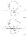
- FIG. 1 a shows a schematic view of a section of a conveyor belt 1.
- a calibration run of a printing press for calibrating pressure registers is described below.
- the conveyor belt 1 is stretched endlessly around deflection rollers 14, 16.
- a printing cylinder 25 is an intermediate cylinder which receives the image from an imaging cylinder 23 and transfers it to a printing material 3.
- the printing cylinder 25 can also apply the image directly.
- the pressure cylinder 25 exerts a force F D on the conveyor belt 1 from above, as shown by the force arrow.
- a pressure roller 27 exerts a force F A opposite the force F D from below onto the conveyor belt 1 of the printing press.
- the pressure roller 27 is mounted pneumatically and exerts a constant constant force F A on the conveyor belt 1 in ideal conditions in FIG.
- the pressure force of the pressure roller 27 does not change here.
- the pressure roller 27 yields when the printing material 3 runs into a printing nip or nip 9, without the pressure of the printing cylinder 25 on the conveyor belt 1 changing.
- the conveyor belt 1 is driven by a motor, moves at a certain speed in the direction of the arrow and moves the pressure cylinder 25 and the pressure roller 27 by friction.
- the three lines which run in the impression cylinder 25 from the axis to the circumference of the impression cylinder 25 symbolically illustrate the spacing of image lines and are shown far apart for clarity. At the intersections of the three lines with the circumference of the printing cylinder 25, an image line is printed on the printing material 3.
- the distances of the image lines in Fig. 1a are ideal and without register errors.
- the influence of changing pressure forces of the pressure roller 27 has no effect in FIG. 1a.
- Fig. 1b shows a similar representation to Fig. 1a with the influence of a second Register error.
- the contact pressure of the Pressure roller 27 is variable.
- the three lines in the pressure cylinder 25 are further apart away. It follows that the image lines on the substrate 3 more Have a distance from each other than in comparison to FIG. 1a, the resolution of the image lines has changed. When printing the three image lines on the substrate 3 the three image lines are at a greater distance from one another.
- the angular velocity of the printing cylinder 25 is approximately constant.
- the second register error a changed resolution of the Image lines, is caused by the fact that when a compressible printing material 3, the contact pressure resulting from the contact roller 27, elevated.
- the substrate 3 expands for the same reasons from, whereby this contributes less to the displayed effect than the increasing contact pressure.
- Fig. 1b the influence of changing pressure forces of the pressure roller acts 27 off and causes a second register error.
- the above effect occurs all the more when a sheet 3 enters the nip 9 and in the event of runout fluctuations of the pressure cylinder 25 or the pressure roller 27. As a result the print image is falsified.
- the change in the resolution of the image lines i.e. the Distances of the image lines from each other is by measuring the register marks as well of the angle of rotation of the imaging cylinder 23 can be determined.
- FIG. 2a shows a schematic view of a section of a conveyor belt 1.
- the conveyor belt 1 is stretched endlessly around deflection rollers 14, 16.
- a printing cylinder 25 is an intermediate cylinder which receives the image from an imaging cylinder 23 and transfers it to a printing material 3 or the conveyor belt 1.
- the printing cylinder 25 exerts a force F D1 on the conveyor belt 1 from above, as shown by the force arrow.
- a pressure roller 27 exerts a force F A1 opposite the force F D1 on the conveyor belt 1 of the printing press from below.
- the pressure roller 27 is mounted pneumatically and exerts a variable force F A1 on the conveyor belt 1.
- the pressure roller 27 yields to a certain extent as the force F D1 of the pressure cylinder 25 increases, but the pressure of the pressure cylinder 25 fluctuates on the conveyor belt 1.
- the conveyor belt 1 is driven by a motor, moves at a certain speed in the direction of the arrow and moves the pressure cylinder 25 and the pressure roller 27 by friction. 2a, the pressure cylinder 25 has a speed v 1 .
- the speed v 1 of the pressure cylinder 25 changes with the contact pressure acting through the forces F D1 and F A1 . The higher the contact pressure of the printing cylinder 25, the more the rotational speed of the printing cylinder 25 decreases.
- a change in the rotational speed of the printing cylinder 25 has an effect on the application of the image in register and leads to errors in the transfer of an image frame or frame in register, which leads to a wrong time is applied.
- image frame or frame denotes a frame of register marks which are applied by the various printing modules of the printing press.
- the frame contains, for example, the register marks for the colors cyan, magenta, yellow and key, which are applied to the printing material 3 or the conveyor belt 1 by the corresponding printing modules.
- the picture frame or frame comprises the entire picture information of one color for the printing material 3 to be printed.
- the incorrect transfer of the picture frame or frame onto the printing material 3 or onto the conveyor belt 1 is referred to in the present description as the first register error.
- the errors in the picture frame or frame caused by the above effects can be demonstrated by measuring the displacements of the register marks compared to the correct position of the register marks.
- Fig. 2b shows a similar representation to Fig. 2a.
- printing material 3 here a sheet of paper which is conveyed by the conveyor belt 1.
- the printing material 3 is generally held on the conveyor belt 1 to a small extent by its own weight and to a greater extent by electrostatic charging. Due to its thickness, the printing substrate 3 additionally influences the contact pressure of the printing cylinder 25.
- the force acting on the printing substrate 3 from the printing cylinder 25 is now caused by the printing substrate 3, equal to F D2 and not equal to F D1 , under otherwise the same conditions as in FIG.
- the changed rotational speed v 2 causes the first register error, which increases with increasing thickness of the printing material 3 in the printing nip or nip 9.
- the changed rotational speed v 2 only has an effect on a sheet 3 following the current sheet 3 in the nip 9 on the conveyor belt 1.
- the second register error the changed contact pressure already affects the current sheet 3 in the nip 9 on the conveyor belt 1. Assume that the time of printing on the printing material 3 by the printing cylinder 25 above the printing material 3 is adapted to a specific speed of the printing cylinder 25.
- the imaging of an imaging cylinder 23 or the printing cylinder 25 by an imaging device 22 is carried out at a point in time that the imaging cylinder 23 or the printing cylinder 25 delivers the concrete image at a predetermined, adjusted rotational speed v 1 at the desired point in time in the space between the printing material 3 and the imaging cylinder 23 or impression cylinder 25, the nip 9, transmits.
- the rotational speed v 2 is not equal to F D2 or F A2 and not to the adapted rotational speed v 1 due to variable contact pressures of the printing cylinder 25 and the pressure roller 27, F D 1 and F A 1 , the printing is carried out on the surface of the printing material 3 or Transport belt 1 not in time, but delayed by the distance that the printing cylinder 25 travels less due to the difference in rotational speed v 2 - v 1 .
- the rotational speed change of the printing cylinder 25 is not only due to the influence described of a printing material 3 occurs, but also due to further influences, such as temperature changes and consequent changes in the circumference of the printing cylinder 25.
- FIG. 3 shows a schematic side view of a printing module of a printing press with the endless conveyor belt 1, which around a first deflection roller 16 and is tensioned around a second deflection roller 14 and by these in the direction of the arrow is moved.
- the pressure roller 27 is arranged below the conveyor belt 1, which presses on the conveyor belt 1 with a contact pressure from below and one Provides counterforce to a pressing force of the pressure cylinder 25.
- the impression cylinder 25 is an intermediate cylinder, which is the stressed image receives from an imaging cylinder 23, that of an imaging device 22 with the stressed image.
- the imaging device 22 comprises the devices required for this, a device for electrostatic Charging the photoconductive surface of the imaging cylinder 23, a controlled light source, such as an LED row, which the photoconductive surface of the imaging cylinder 23 with a latent electrostatic image, which is colored by a development unit with toner and a too results in printing image, as well as cleaning devices for removing excess Toner after transferring the image to the substrate 3 and for that Reimaging of the imaging cylinder 23.
- the second deflection roller 14 is a first encoder 24 assigned, the imaging cylinder 23 is a second Assigned encoder 26. The first encoder 24 and the second encoder 26 detect the angle of rotation of the second deflection roller at certain short intervals 14 or the imaging cylinder 23.
- the first encoder 24 sends signals with regard to the angle of rotation of the second deflection roller 14 to the clock counter 20 and the device 30.
- the angle of rotation of the second deflection roller 14 is therefore in the device 30 and in the clock counter 20 before.
- a clock counter 20 is connected to a device 30, to a first Sensor 12 in front of the printing modules of the printing press, with a clock divider 21 and is connected to the first encoder 24.
- a second sensor 13 behind the Printing modules of the printing press is connected to the device 30.
- the clock divider 21 is also with the device 30, with the imaging device 22 and connected to the second encoder 26 on the imaging cylinder 23.
- the first sensor 12 detects in front of the printing modules of the printing press the front edge of a printing material 3, which transports on the conveyor belt 1 becomes.
- the first sensor 12 transmits in response to the detection of the leading edge of the substrate 3 a signal, also lead edge signal, to the clock counter 20.
- This signal becomes a first after a certain number of cycles Start signal that generates the START OF FRAME signal, which is used for imaging by the imaging device 22 at exactly the right time when Triggering the START OF FRAME signal, triggering a picture frame or frame in time on the imaging cylinder 23 and ultimately on the printing material 3 - or also for the purpose of the calibration described here the conveyor belt 1 - is transferred.
- image frame or frame refers to during the calibration run, a frame of register marks that the various printing modules of the printing press are applied.
- the frame contains, for example, the register marks for the in a four-color printing press Colors cyan, magenta, yellow and key by the corresponding printing modules be applied to the printing material 3 or the conveyor belt 1.
- On Picture frames or frames can also be used for special sections of those described here Calibrate a number of register marks for each color exhibit.
- the frame or picture frame includes the all image information for the printing material 3 to be printed for one color, such as cyan, magenta, yellow and key.
- a second start signal the START OF LINE signal which generates the imaging of individual lines of the image perpendicular to the direction of travel of the printing material 3 through the Imaging device 22 triggers.
- the START OF LINE signal With each START OF LINE signal one Image line written on the imaging cylinder 23, a first image line at Beginning of the frame, subsequent picture lines and a last picture line at the end of the frame.
- the START OF LINE signal is obtained by dividing the clock by a divider factor generated by the device 30 in the clock divider 21.
- the clock divider 21 receives data from the second encoder 26 with respect to the angle of rotation of the imaging cylinder 23 and divides this data according to the divider factor.
- nip 9 or printing nip the area between the printing cylinder 25 and the conveyor belt 1 or substrate 3, register marks are transferred to the conveyor belt 1 or printing material 3, the pressure roller 27 from below of the conveyor belt 1 presses against this and a counterforce to the pressing force of the printing cylinder 25 provides.
- the second Sensor 13 also called register sensor, is detected behind the pressure modules.
- second sensor 13 detects the light / dark transition between the respective ones Register mark and the background of this register mark, the conveyor belt 1 or printing material 3.
- the second sensor 13 transmits in response to the detection of the individual register marks a signal to the device 30.
- the device 30 transmits the angle of rotation of the encoder 26 at the time of the START OF FRAME at the time of the START OF FRAME.
- the device 30 includes variable ones and unchangeable data related to the START OF FRAME signal and to the START OF LINE signal, which leads to the clock counter 20 or the clock divider 21 are transmitted and the illustration of the picture frames or frames or the Trigger image lines by the imaging device 22 at the right time.
- the unchangeable Data of the device 30 identify the target times at which the imaging by the imaging device 22 without external influences and error influences are triggered.
- the changing data carry changes Invoice that lead to the imaging during the course of the calibration run Has errors.
- the changing data to correct the influence the variable contact pressure of the pressure roller 27 are from the data of second sensor 13 and the second rotary encoder 26 in the imaging cylinder 23 educated.
- the corresponding variables without the influence of errors form the unchangeable ones Data of the device 30, which are ideal data.
- the variable sizes include deviations and errors from the ideal data and form the variable ones Data of the facility 30.
- the changeable data are by means of Calibration runs of the printing press determined by using the error influences deviations of the register marks can be determined over time.
- the influences of errors include temperature influences on the imaging cylinder 23 and in particular on the pressure cylinder 25, which leads to circumferential changes to lead.
- the effects of errors include concentricity errors in the printing cylinder 25 or the imaging cylinder 23, which is a periodic change in Path length for the individual image lines from the imaging device 22 to Nip 9 result.
- data gives the delay data of the device 30, which leads to the clock counter 20 are transmitted, the clock numbers corresponding to this delay data counts, after which a trigger signal or start signal to the imaging device 22 is sent to apply an image to the imaging cylinder 23 the first start signal, START OF FRAME signal.
- the delay dates cycle numbers are assigned to this.
- the clock counter 20 counts a number of Clocking, which is determined by the delay data, after which immediately one START OF FRAME signal is generated.
- the clock divider 21 which starts with the generation of START OF LINE signals begin, which is triggered by the START OF FRAME signal is.
- the START OF LINE signals result from the division of the clocks of the encoder 26 by the divisors.
- the illustration is of a frame is triggered, with the START OF LINE signal the imaging is a picture line triggered.
- This first register error also called a delay error, is generated during the calibration run measured by the second sensor 13 or register sensor.
- the the Divider factor data of the clock divider 21 associated with the device 30 clock numbers are necessary for the register print, the lower the higher the through the contact pressure of the pressure cylinder 25 caused expansion of the coating of the Rubber blanket of the impression cylinder 25 is, see Fig. 1a, 1b.
- This second register error also called magnification error, is during the calibration run by measuring the register marks by the second sensor 13 or register sensor and the angle of rotation by the encoder 26 and subsequent Calculate determined from the measurement data obtained. To that through the expansion of the rubber blanket caused a change in the resolution of the image lines the clock number is reduced by the clock divider 21.
- the image lines move together by the amount around which this is due to the expansion of the rubber blanket covering have moved apart, i.e. the picture lines move closer together and the second register error is corrected.
- the unchangeable data in the device 30 are not sufficient to print with high accuracy in register.
- the number of cycles after which the START OF FRAME signal is generated is therefore composed of both the unchangeable data and the changeable data.
- influences on the register stability for example changes in the rotational speed of the printing cylinder 25 or also concentricity fluctuations of the printing cylinder 25 and of the imaging cylinder 23, are corrected, the first register error and the second register error.
- the variable data are related to the sensor data of the second sensor 13 or to the angles of rotation of the second deflection roller 14, the imaging cylinder 23 and the printing cylinder 25.
- the variable proportion of both the delay data and the divider factors is related to the contact pressure.
- a higher contact pressure of the pressure roller 27 and consequently of the printing cylinder 25 causes both a displacement of the picture frame or frame and also more distant picture lines of the printed picture, the printed picture expands and has a greater length extension.
- the effect of a changing contact pressure increases, which increases with increasing thickness of the printing material 3.
- Substrates 3 of different thicknesses consequently cause different first register errors and second register errors.
- the thickness of the printing substrate 3 is used as a proportion of the variable data in the device 30.
- the variable data relating to the thickness of the printing substrate 3 are fed into the device 30 before the printing process, ie after the calibration run, and are then available.
- the variable data with respect to the thickness of the printing substrate 3 are determined during a calibration run, the changing data from the rotational speed difference from v 1 , without printing substrate 3 in the nip 9, and v 2 , with printing substrate 3 in the nip 9, can be calculated.
- the resolution of adjacent image lines is influenced by the nature of the printing material 3. With less compressible cardboard, for example, the spacing between adjacent image lines increases compared to, for example, soft compressible paper.
- the nature of the printing substrate 3 is therefore used in a manner corresponding to the thickness of the printing substrate 3 as a component for the delay data which determine the times for the first start signal, the START OF FRAME signal and for the second start signal, the START OF LINE signal.
- the individual parts described above, the part with regard to the thickness and nature of the printing material 3, the unchangeable and changeable data, are added and give the delay data of the device 30.
- the delay data results in a number of cycles, which is counted in the clock counter 20, and the illustration , triggered by the first start signal and the second start signal, at a different time than originally caused, insofar as errors are present.
- a specific calibration run for calibrating first register errors or delay errors is as described below.
- the conveyor belt 1 is first operated in a first calibration sequence without a sheet 3 and the first register error is determined as above.
- the conveyor belt 1 is then operated in a second calibration sequence with a plurality of consecutive sheets 3.
- the frames are located between the sheets 3. Due to the influence of the sheets 3, the pressing force of the pressing roller 27 is changed and the frames, which include the register marks, are shifted. This shift in the frames, which corresponds to the first register error, is measured by means of the second sensor 13.
- the conveyor belt 1 is then operated in a third calibration sequence again without the sheet 3 and the first register error is measured.
- the first register error in the situation without sheet 3 on the conveyor belt 1 is determined from both the first and the third calibration sequence.
- a steady increase or decrease in the first register error over the entire calibration run for example as a result of a thermal drift, can thus be mathematically removed by averaging.
- the two first register errors thus determined, with and without a sheet 3 on the conveyor belt 1, are then compared.
- a specific calibration run for calibrating second register errors or magnification errors is as described below.
- the calibration run described above for the first register error can be used if 3 frames with register marks are also printed on the sheet.
- the resolution of the image lines on the sheet 3 is measured, on the other hand the resolution of the image lines on the conveyor belt 1.
- signals from the second sensor 13, the first rotary encoder 24 and the second rotary encoder 26 are used.
- the measured second register errors on the conveyor belt 1 and on the sheet 3 are then compared with one another.
- the variable data are calculated from the difference from the comparison. In the manner described above, the influence of a variable pressure force of a pressure roller 27 on the register-based printing is reliably corrected.
Landscapes
- Physics & Mathematics (AREA)
- General Physics & Mathematics (AREA)
- Inking, Control Or Cleaning Of Printing Machines (AREA)
- Handling Of Sheets (AREA)
- Controlling Sheets Or Webs (AREA)
- Electrostatic Charge, Transfer And Separation In Electrography (AREA)
- Control Or Security For Electrophotography (AREA)
Abstract
Description
In besonders vorteilhafter Weise werden die Startsignale an den Fall angepasst, wenn sich Bedruckstoff zwischen dem Druckzylinder und dem Transportband befindet. In diesem Fall ändert sich die Anpresskraft des Druckzylinders und folglich der Registerfehler in besonders starker Weise. Weiterhin können die Startsignale zu den Eigenschaften eines Bedruckstoffs in Bezug stehen. Auf diese Weise wird der unterschiedlichen Änderung der Bildzeilenauflösung, d.h. der Abstände der Bildzeilen auf dem Bedruckstoff zueinander, bei verschiedenen Bedruckstoffen bezüglich sich ändernder Anpresskräfte Rechnung getragen. Die Anpresskraft der Anpressrolle steigt stets dann an, wenn die Anpressrolle verschoben wird. In diesem Fall wirken zunehmende Kräfte der pneumatischen Lagerung der Anpressrolle gegen diese. Beispielsweise wirkt sich eine veränderliche Anpresskraft der Anpressrolle bei einem stark komprimierbaren Bedruckstoff weniger als bei einem geringfügig komprimierbaren Bedruckstoff aus, da die Anpressrolle bei einem stark komprimierbaren Bedruckstoff nicht so stark ausgelenkt wird wie bei einem geringfügig komprimierbaren Bedruckstoff. Je höher die Auslenkung der Anpressrolle ist, je größer wir die Anpresskraft. Bei einem stark komprimierbaren Bedruckstoff rücken die Bildlinien weniger auseinander als bei einem geringfügig komprimierbaren Bedruckstoff, wenn sich die Anpresskraft der Anpressrolle und folglich des Druckzylinders auf den Bedruckstoff erhöht. Die Anpresskraft der Anpressrolle hängt mit der Anpresskraft des Druckzylinders zusammen, da die Anpressrolle gegenüber dem Druckzylinder angeordnet ist und deren Kräfte gegeneinander wirken. Außerdem wird die Dicke des Bedruckstoffs berücksichtigt, die sich auf die Anpresskraft der Anpressrolle auswirkt, da die Anpresskraft im Verhältnis zum Weg steht, um den die Anpressrolle aufgrund des Bedruckstoffs im Druckspalt oder Nip verschoben wird.
Im folgenden ist die Erfindung bezüglich der Fig. in Einzelheiten beschrieben.
- Fig. 1a, Fig. 1b
- zeigen jeweils eine schematische Ansicht eines Abschnitts eines Transportbands mit einem Druckzylinder oberhalb des Transportbands und einer Anpressrolle unterhalb des Transportbands zur Verdeutlichung des Prinzips des zweiten Registerfehlers,
- Fig. 2a
- zeigt eine schematische Ansicht eines Abschnitts eines Transportbands mit einem Druckzylinder oberhalb des Transportbands und einer Anpressrolle unterhalb des Transportbands zur Verdeutlichung der wirkenden Kräfte ohne Bedruckstoff,
- Fig. 2b
- zeigt eine schematische Ansicht eines Abschnitts eines Transportbands mit einem Druckzylinder oberhalb des Transportbands und einer Anpressrolle unterhalb des Transportbands zur Verdeutlichung der wirkenden Kräfte mit Bedruckstoff,
- Fig. 3
- zeigt eine schematische Ansicht eines Druckmoduls einer Druckmaschine als Ausführungsform der Erfindung.
Claims (6)
- Verfahren zum Vermeiden von Registerfehlern bei Druckmaschinen, dadurch gekennzeichnet, dass die Registerfehler durch die veränderliche Anpresskraft einer an ein Transportband (1) angreifenden Anpressrolle (27) verursacht werden und dass zum Vermeiden eines ersten Registerfehlers Zeitpunkte von ersten Startsignalen (START OF FRAME) für das Aufbringen von Bildrahmen oder Frames verändert werden und zum Vermeiden eines zweiten Registerfehlers Zeitpunkte von zweiten Startsignalen (START OF LINE) für das Aufbringen von Bildlinien verändert werden.
- Verfahren nach Anspruch 1, dadurch gekennzeichnet, dass ein erster Sensor (12) vor Druckmodulen der Druckmaschine einen Bedruckstoff (3) erfasst, die Druckmodule Registermarken auf den Bedruckstoff (3) und auf das Transportband (1) aufbringen, ein zweiter Sensor (13) hinter den Druckmodulen die aufgebrachten Registermarken erfasst, ein Drehgeber (26) den Drehwinkel eines Druckzylinders (25) erfasst und aus den erfassten Daten und in einer Einrichtung (30) gespeicherten unveränderlichen Daten ohne Beeinflussung durch die Anpressrolle (27) die Zeitpunkte der Startsignale (START OF FRAME, START OF LINE) berechnet werden.
- Verfahren nach Anspruch 1 oder 2, dadurch gekennzeichnet, dass in einem ersten Fall die Zeitpunkte der Startsignale (START OF FRAME, START OF LINE) verwendet werden, wenn sich Bedruckstoff (3) zwischen dem Druckzylinder (25) und dem Transportband (1) befindet, und in einem zweiten Fall andere Zeitpunkte der Startsignale (START OF FRAME, START OF LINE), wenn sich kein Bedruckstoff (3) zwischen dem Druckzylinder (25) und dem Transportband (1) befindet.
- Verfahren nach Anspruch 3, dadurch gekennzeichnet, dass die Zeitpunkte der Startsignale (START OF FRAME, START OF LINE) zu den Eigenschaften eines Bedruckstoffs (3) in Bezug stehen.
- Steuerungseinrichtung (10) zum Vermeiden von Registerfehlern bei Druckmaschinen, vorzugsweise zum Anwenden des Verfahrens nach Anspruch 1, gekennzeichnet durch eine Bebilderungseinrichtung (22) zum Übertragen von Bildlinien auf einen Druckzylinder (25), einen ersten Sensor (12) zum Erfassen eines Bedruckstoffs (3) vor den Druckmodulen, einen zweiten Sensor (13) zum Erfassen von Registermarken hinter den Druckmodulen, einen Drehgeber (26) zum Erfassen des Drehwinkels des Druckzylinders (25) und eine Einrichtung (30) zum Speichern von Zeitpunkten von ersten Startsignalen (START OF FRAME) für das Aufbringen von Bildrahmen oder Frames und von zweiten Startsignalen (START OF LINE) für das Aufbringen von Bildlinien, die durch die veränderliche Anpresskraft einer an das Transportband (1) angreifenden Anpressrolle (27) bestimmt sind.
- Steuerungseinrichtung (10) nach Anspruch 5, dadurch gekennzeichnet, dass die Einrichtung (30) Daten bezüglich der Eigenschaften des Bedruckstoffs (3) umfasst.
Applications Claiming Priority (2)
| Application Number | Priority Date | Filing Date | Title |
|---|---|---|---|
| DE10208597A DE10208597B4 (de) | 2002-02-27 | 2002-02-27 | Verfahren zum Vermeiden von Registerfehlern bei einer Druckmaschine |
| DE10208597 | 2002-02-27 |
Publications (1)
| Publication Number | Publication Date |
|---|---|
| EP1341054A1 true EP1341054A1 (de) | 2003-09-03 |
Family
ID=27675091
Family Applications (1)
| Application Number | Title | Priority Date | Filing Date |
|---|---|---|---|
| EP02025148A Withdrawn EP1341054A1 (de) | 2002-02-27 | 2002-11-09 | Verfahren und Steuerungseinrichtung zum Vermeiden von Registerfehlern |
Country Status (4)
| Country | Link |
|---|---|
| US (1) | US6836635B2 (de) |
| EP (1) | EP1341054A1 (de) |
| JP (1) | JP2003255802A (de) |
| DE (1) | DE10208597B4 (de) |
Families Citing this family (9)
| Publication number | Priority date | Publication date | Assignee | Title |
|---|---|---|---|---|
| DE10305047B4 (de) * | 2002-10-11 | 2010-08-12 | Eastman Kodak Company | Verfahren zur Kalibrierung des passergenauen Druckprozesses einer Farbdruckmaschine |
| DE10304763A1 (de) * | 2003-02-05 | 2004-08-26 | Nexpress Solutions Llc | Verfahren zur Korrektur der Kalibrierung eines passergenauen Druckprozesses |
| JP2005324386A (ja) * | 2004-05-13 | 2005-11-24 | Dainippon Printing Co Ltd | グラビア印刷機、追刷見当制御装置、および追刷方法 |
| US7126621B2 (en) * | 2004-07-30 | 2006-10-24 | Xerox Corporation | Printer using hybrid reflex writing to color register an image |
| DE102006009773A1 (de) * | 2006-03-01 | 2007-09-06 | Eastman Kodak Co. | Verfahren zum Vermeiden eines Passerfehlers beim Drucken |
| KR101409485B1 (ko) | 2012-10-25 | 2014-06-18 | 한국기계연구원 | 롤투롤 공정의 레지스터마크 오차 계측방법 |
| JP2020118921A (ja) * | 2019-01-28 | 2020-08-06 | キヤノン株式会社 | 画像形成装置 |
| US11822262B2 (en) | 2021-09-28 | 2023-11-21 | Eastman Kodak Company | Registration of white toner using sensing system with colored reflector plate |
| US11829084B2 (en) | 2021-09-28 | 2023-11-28 | Eastman Kodak Company | Registration of white toner in an electrophotographic printer |
Citations (5)
| Publication number | Priority date | Publication date | Assignee | Title |
|---|---|---|---|---|
| EP0291738A1 (de) * | 1987-04-28 | 1988-11-23 | Canon Kabushiki Kaisha | Gerät zur Multibilderzeugung |
| EP0821283A1 (de) * | 1996-07-25 | 1998-01-28 | Océ-Technologies B.V. | Bilddruckapparat |
| EP0859288A1 (de) * | 1997-02-17 | 1998-08-19 | Océ-Technologies B.V. | Verfahren zur automatischen Bildaufnahmekorrektur und dieses Verfahren verwendendes Bildübertragungssystem |
| EP1157837A2 (de) * | 2000-05-17 | 2001-11-28 | NexPress Solutions LLC | Verfahren und Vorrichtung zur Registereinstellung an einer Mehrfarbendruckmaschine |
| EP1285758A1 (de) * | 2001-08-09 | 2003-02-26 | NexPress Solutions LLC | Verfahren und Bebilderungseinrichtung zur Registereinstellung |
Family Cites Families (4)
| Publication number | Priority date | Publication date | Assignee | Title |
|---|---|---|---|---|
| US5287162A (en) * | 1992-06-16 | 1994-02-15 | Xerox Corporation | Method and apparatus for correction of color registration errors |
| US5284162A (en) * | 1992-07-14 | 1994-02-08 | Wilk Peter J | Method of treating the colon |
| DE19934658A1 (de) * | 1999-07-23 | 2001-01-25 | Nexpress Solutions Llc | Druckvorrichtung |
| DE50113847D1 (de) * | 2000-05-17 | 2008-05-29 | Eastman Kodak Co | Verfahren und Vorrichtung zur Registereinstellung an einer Mehrfarbendruckmaschine sowie Mehrfarbendruckmaschine |
-
2002
- 2002-02-27 DE DE10208597A patent/DE10208597B4/de not_active Expired - Fee Related
- 2002-11-09 EP EP02025148A patent/EP1341054A1/de not_active Withdrawn
-
2003
- 2003-02-07 US US10/360,284 patent/US6836635B2/en not_active Expired - Lifetime
- 2003-02-25 JP JP2003048034A patent/JP2003255802A/ja active Pending
Patent Citations (5)
| Publication number | Priority date | Publication date | Assignee | Title |
|---|---|---|---|---|
| EP0291738A1 (de) * | 1987-04-28 | 1988-11-23 | Canon Kabushiki Kaisha | Gerät zur Multibilderzeugung |
| EP0821283A1 (de) * | 1996-07-25 | 1998-01-28 | Océ-Technologies B.V. | Bilddruckapparat |
| EP0859288A1 (de) * | 1997-02-17 | 1998-08-19 | Océ-Technologies B.V. | Verfahren zur automatischen Bildaufnahmekorrektur und dieses Verfahren verwendendes Bildübertragungssystem |
| EP1157837A2 (de) * | 2000-05-17 | 2001-11-28 | NexPress Solutions LLC | Verfahren und Vorrichtung zur Registereinstellung an einer Mehrfarbendruckmaschine |
| EP1285758A1 (de) * | 2001-08-09 | 2003-02-26 | NexPress Solutions LLC | Verfahren und Bebilderungseinrichtung zur Registereinstellung |
Also Published As
| Publication number | Publication date |
|---|---|
| DE10208597A1 (de) | 2003-09-11 |
| DE10208597B4 (de) | 2013-03-21 |
| US20040086304A1 (en) | 2004-05-06 |
| JP2003255802A (ja) | 2003-09-10 |
| US6836635B2 (en) | 2004-12-28 |
Similar Documents
| Publication | Publication Date | Title |
|---|---|---|
| DE10132266B4 (de) | Verfahren zur Regelung des Übergabepassers in einer Bogenrotationsdruckmaschine | |
| EP1157837B1 (de) | Verfahren zur Registereinstellung an einer Mehrfarbendruckmaschine | |
| EP1572457B1 (de) | Vorregistereinstellung | |
| EP2045076B1 (de) | Rollendruckmaschine | |
| EP1285756B1 (de) | Verfahren und Druckmaschine zum Ermitteln von Registerfehlern | |
| EP3539777B1 (de) | Verfahren und vorrichtung zum korrigieren einer druckposition eines druckwerks sowie druckmaschine | |
| DE4244276A1 (de) | Anordnung zum Messen der Lage einer Bogenkante auf der Oberfläche eines rotierenden Zylinders | |
| DE102013202873A1 (de) | Tandemdrucksystem mit Bahntransport-Controller mit abgeleitetem Trommeldurchmesser | |
| EP1285757B1 (de) | Verfahren und Druckmaschine zum Ermitteln von Registerfehlern | |
| DE10208597B4 (de) | Verfahren zum Vermeiden von Registerfehlern bei einer Druckmaschine | |
| DE10139310B4 (de) | Verfahren zum Ermitteln von START OF FRAME-Korrekturdaten und START OF LINE-Korrekturdaten zur Registereinstellung für Druckmaschinen beim Mehrfarbdruck | |
| DE10300903A1 (de) | Doppeldrucksystem | |
| EP1156384B1 (de) | Verfahren und Vorrichtung zur Registereinstellung an einer Mehrfarbendruckmaschine sowie Mehrfarbendruckmaschine | |
| DE102006009773A1 (de) | Verfahren zum Vermeiden eines Passerfehlers beim Drucken | |
| DE10227766A1 (de) | Verfahren und Steuerungseinrichtung zum Vermeiden von Registerfehlern | |
| EP1396341B1 (de) | Verfahren und Steuerungseinrichtung zum Bestimmen eines Registerfehlers | |
| EP1759844B1 (de) | Verfahren zur Druckkorrektur | |
| EP1156400A1 (de) | Verfahren und Vorrichtung zur Einstellung des Registers für deckunsgleichen Schön- und Widerdruck bei einer Mehrfarbendruckmaschine | |
| KR102337482B1 (ko) | 정보처리장치, 인쇄시스템 및 정보처리방법 | |
| EP2862715A2 (de) | Druckmaschine | |
| DE10304763A1 (de) | Verfahren zur Korrektur der Kalibrierung eines passergenauen Druckprozesses | |
| EP1482383A1 (de) | Verfahren und Steuerungseinrichtung zum Vermeiden von Registerfehlern | |
| DE2259761A1 (de) | Vorrichtung zum erfassen und aussortieren von makulatur | |
| DE10239158A1 (de) | Steuerungseinrichtung und Verfahren zum Vermeiden von Registerfehlern | |
| EP1158776A2 (de) | Verfahren und Vorrichtung zur Korrektur von Registerfehlern bei einer Mehrfarbendruckmaschine |
Legal Events
| Date | Code | Title | Description |
|---|---|---|---|
| PUAI | Public reference made under article 153(3) epc to a published international application that has entered the european phase |
Free format text: ORIGINAL CODE: 0009012 |
|
| AK | Designated contracting states |
Kind code of ref document: A1 Designated state(s): AT BE BG CH CY CZ DE DK EE ES FI FR GB GR IE IT LI LU MC NL PT SE SK TR |
|
| AX | Request for extension of the european patent |
Extension state: AL LT LV MK RO SI |
|
| 17P | Request for examination filed |
Effective date: 20040303 |
|
| AKX | Designation fees paid |
Designated state(s): AT BE BG CH CY CZ DE DK EE ES FI FR GB GR IE IT LI LU MC NL PT SE SK TR |
|
| RAP1 | Party data changed (applicant data changed or rights of an application transferred) |
Owner name: EASTMAN KODAK COMPANY |
|
| 17Q | First examination report despatched |
Effective date: 20041111 |
|
| 17Q | First examination report despatched |
Effective date: 20041111 |
|
| STAA | Information on the status of an ep patent application or granted ep patent |
Free format text: STATUS: THE APPLICATION IS DEEMED TO BE WITHDRAWN |
|
| 18D | Application deemed to be withdrawn |
Effective date: 20070208 |