EP1340670A1 - Module de roue indépendant et véhicule utilisant ce module - Google Patents
Module de roue indépendant et véhicule utilisant ce module Download PDFInfo
- Publication number
- EP1340670A1 EP1340670A1 EP03290356A EP03290356A EP1340670A1 EP 1340670 A1 EP1340670 A1 EP 1340670A1 EP 03290356 A EP03290356 A EP 03290356A EP 03290356 A EP03290356 A EP 03290356A EP 1340670 A1 EP1340670 A1 EP 1340670A1
- Authority
- EP
- European Patent Office
- Prior art keywords
- steering
- vehicle
- chassis
- wheel
- module
- Prior art date
- Legal status (The legal status is an assumption and is not a legal conclusion. Google has not performed a legal analysis and makes no representation as to the accuracy of the status listed.)
- Granted
Links
- 239000000725 suspension Substances 0.000 claims abstract description 57
- 230000006870 function Effects 0.000 claims description 33
- 238000006073 displacement reaction Methods 0.000 claims description 9
- 239000012530 fluid Substances 0.000 claims description 6
- 230000005484 gravity Effects 0.000 claims description 4
- 238000013016 damping Methods 0.000 claims description 3
- 230000036961 partial effect Effects 0.000 claims description 3
- 238000005096 rolling process Methods 0.000 claims description 2
- 101100134883 Caenorhabditis elegans dlat-1 gene Proteins 0.000 claims 1
- 230000008878 coupling Effects 0.000 abstract description 5
- 238000010168 coupling process Methods 0.000 abstract description 5
- 238000005859 coupling reaction Methods 0.000 abstract description 5
- 238000010276 construction Methods 0.000 description 6
- 230000000694 effects Effects 0.000 description 4
- 239000006096 absorbing agent Substances 0.000 description 2
- 230000007659 motor function Effects 0.000 description 2
- 230000010355 oscillation Effects 0.000 description 2
- 230000035939 shock Effects 0.000 description 2
- 238000004904 shortening Methods 0.000 description 2
- 241000238557 Decapoda Species 0.000 description 1
- 238000000429 assembly Methods 0.000 description 1
- 230000005540 biological transmission Effects 0.000 description 1
- 230000006835 compression Effects 0.000 description 1
- 238000007906 compression Methods 0.000 description 1
- 230000001419 dependent effect Effects 0.000 description 1
- 230000006866 deterioration Effects 0.000 description 1
- 238000009826 distribution Methods 0.000 description 1
- 230000010354 integration Effects 0.000 description 1
- 238000012423 maintenance Methods 0.000 description 1
- 238000004519 manufacturing process Methods 0.000 description 1
- 239000004570 mortar (masonry) Substances 0.000 description 1
- 230000035515 penetration Effects 0.000 description 1
- 230000000284 resting effect Effects 0.000 description 1
- 238000004804 winding Methods 0.000 description 1
Images


Classifications
-
- B—PERFORMING OPERATIONS; TRANSPORTING
- B62—LAND VEHICLES FOR TRAVELLING OTHERWISE THAN ON RAILS
- B62D—MOTOR VEHICLES; TRAILERS
- B62D7/00—Steering linkage; Stub axles or their mountings
- B62D7/06—Steering linkage; Stub axles or their mountings for individually-pivoted wheels, e.g. on king-pins
-
- B—PERFORMING OPERATIONS; TRANSPORTING
- B60—VEHICLES IN GENERAL
- B60G—VEHICLE SUSPENSION ARRANGEMENTS
- B60G3/00—Resilient suspensions for a single wheel
- B60G3/18—Resilient suspensions for a single wheel with two or more pivoted arms, e.g. parallelogram
- B60G3/20—Resilient suspensions for a single wheel with two or more pivoted arms, e.g. parallelogram all arms being rigid
-
- B—PERFORMING OPERATIONS; TRANSPORTING
- B62—LAND VEHICLES FOR TRAVELLING OTHERWISE THAN ON RAILS
- B62D—MOTOR VEHICLES; TRAILERS
- B62D53/00—Tractor-trailer combinations; Road trains
- B62D53/005—Combinations with at least three axles and comprising two or more articulated parts
-
- B—PERFORMING OPERATIONS; TRANSPORTING
- B62—LAND VEHICLES FOR TRAVELLING OTHERWISE THAN ON RAILS
- B62D—MOTOR VEHICLES; TRAILERS
- B62D7/00—Steering linkage; Stub axles or their mountings
- B62D7/06—Steering linkage; Stub axles or their mountings for individually-pivoted wheels, e.g. on king-pins
- B62D7/14—Steering linkage; Stub axles or their mountings for individually-pivoted wheels, e.g. on king-pins the pivotal axes being situated in more than one plane transverse to the longitudinal centre line of the vehicle, e.g. all-wheel steering
- B62D7/142—Steering linkage; Stub axles or their mountings for individually-pivoted wheels, e.g. on king-pins the pivotal axes being situated in more than one plane transverse to the longitudinal centre line of the vehicle, e.g. all-wheel steering specially adapted for particular vehicles, e.g. tractors, carts, earth-moving vehicles, trucks
-
- B—PERFORMING OPERATIONS; TRANSPORTING
- B62—LAND VEHICLES FOR TRAVELLING OTHERWISE THAN ON RAILS
- B62D—MOTOR VEHICLES; TRAILERS
- B62D7/00—Steering linkage; Stub axles or their mountings
- B62D7/06—Steering linkage; Stub axles or their mountings for individually-pivoted wheels, e.g. on king-pins
- B62D7/14—Steering linkage; Stub axles or their mountings for individually-pivoted wheels, e.g. on king-pins the pivotal axes being situated in more than one plane transverse to the longitudinal centre line of the vehicle, e.g. all-wheel steering
- B62D7/15—Steering linkage; Stub axles or their mountings for individually-pivoted wheels, e.g. on king-pins the pivotal axes being situated in more than one plane transverse to the longitudinal centre line of the vehicle, e.g. all-wheel steering characterised by means varying the ratio between the steering angles of the steered wheels
- B62D7/1509—Steering linkage; Stub axles or their mountings for individually-pivoted wheels, e.g. on king-pins the pivotal axes being situated in more than one plane transverse to the longitudinal centre line of the vehicle, e.g. all-wheel steering characterised by means varying the ratio between the steering angles of the steered wheels with different steering modes, e.g. crab-steering, or steering specially adapted for reversing of the vehicle
-
- B—PERFORMING OPERATIONS; TRANSPORTING
- B60—VEHICLES IN GENERAL
- B60G—VEHICLE SUSPENSION ARRANGEMENTS
- B60G2200/00—Indexing codes relating to suspension types
- B60G2200/10—Independent suspensions
- B60G2200/14—Independent suspensions with lateral arms
- B60G2200/144—Independent suspensions with lateral arms with two lateral arms forming a parallelogram
-
- B—PERFORMING OPERATIONS; TRANSPORTING
- B60—VEHICLES IN GENERAL
- B60G—VEHICLE SUSPENSION ARRANGEMENTS
- B60G2200/00—Indexing codes relating to suspension types
- B60G2200/40—Indexing codes relating to the wheels in the suspensions
- B60G2200/44—Indexing codes relating to the wheels in the suspensions steerable
-
- B—PERFORMING OPERATIONS; TRANSPORTING
- B60—VEHICLES IN GENERAL
- B60G—VEHICLE SUSPENSION ARRANGEMENTS
- B60G2206/00—Indexing codes related to the manufacturing of suspensions: constructional features, the materials used, procedures or tools
- B60G2206/01—Constructional features of suspension elements, e.g. arms, dampers, springs
- B60G2206/011—Modular constructions
- B60G2206/0112—Bogies for heavy vehicles
-
- B—PERFORMING OPERATIONS; TRANSPORTING
- B60—VEHICLES IN GENERAL
- B60G—VEHICLE SUSPENSION ARRANGEMENTS
- B60G2206/00—Indexing codes related to the manufacturing of suspensions: constructional features, the materials used, procedures or tools
- B60G2206/01—Constructional features of suspension elements, e.g. arms, dampers, springs
- B60G2206/011—Modular constructions
- B60G2206/0114—Independent suspensions on subframes
-
- B—PERFORMING OPERATIONS; TRANSPORTING
- B60—VEHICLES IN GENERAL
- B60G—VEHICLE SUSPENSION ARRANGEMENTS
- B60G2300/00—Indexing codes relating to the type of vehicle
- B60G2300/02—Trucks; Load vehicles
- B60G2300/026—Heavy duty trucks
-
- B—PERFORMING OPERATIONS; TRANSPORTING
- B60—VEHICLES IN GENERAL
- B60G—VEHICLE SUSPENSION ARRANGEMENTS
- B60G2300/00—Indexing codes relating to the type of vehicle
- B60G2300/04—Trailers
-
- B—PERFORMING OPERATIONS; TRANSPORTING
- B60—VEHICLES IN GENERAL
- B60G—VEHICLE SUSPENSION ARRANGEMENTS
- B60G2300/00—Indexing codes relating to the type of vehicle
- B60G2300/14—Buses
-
- B—PERFORMING OPERATIONS; TRANSPORTING
- B60—VEHICLES IN GENERAL
- B60G—VEHICLE SUSPENSION ARRANGEMENTS
- B60G2300/00—Indexing codes relating to the type of vehicle
- B60G2300/38—Low or lowerable bed vehicles
Definitions
- the present invention relates to a wheel module used for construction of a special site or handling machine or vehicle, as well as such a machine or vehicle.
- such devices are often produced in very small series or on order, and are built from a chassis supported by one or more sets of wheels.
- a wheel set is usually designed as a bridge arranged under a frame and supporting a part of this chassis.
- a bridge arranged under a frame and supporting a part of this chassis.
- We can define such a bridge as a set of several wheels distributed on both sides of the chassis, and carried by a structure itself movable relative to the chassis, for example comprising a unsprung axle passing under the chassis.
- This structure may include drive elements for drive wheels, and directions for steered wheels.
- This bridge is thus positioned under the chassis, most often by means of elastic elements and elements shock absorbers, so as to produce a suspension avoiding transmitting to the chassis all the irregularities of the ground during the rolling.
- One of the aims of the invention is thus to propose a connection device on the ground by wheel making it possible to produce a set of wheels supporting a chassis positioned as low as possible.
- Another object of the invention is to propose a vehicle using such a wheel device.
- One of the aims of the invention is thus to propose a vehicle whose several sets of wheels are steering, in parallel or in opposition between them.
- a ground connection module supporting all or part of a vehicle chassis or special construction or handling equipment, this module comprising one or more wheels allowing the movement of all or part of this vehicle, characterized in that at least one of these wheels supports part of the chassis by controlled ground connection means, arranged on at least one side of the chassis, occupying a volume which does not extend not to the middle part of the chassis along the axis of the wheel, and comprising the possibility of a displacement of the axis of the wheel relative to the chassis thus ensuring a suspension function, regardless of the position or the condition of the wheels or ground connection means supporting said chassis and located outside of this module and independently of the axis movement wheels of the other modules in relation to the chassis.
- the wheel is mounted by a pivot link on a rocket, called wheel rocket, this wheel rocket being movable in rotation by relation to the chassis along a direction axis forming with the surface where the wheel leans an angle greater than 45 °, the rotation of the wheel spindle around of this steering axis being controlled by displacement of an element, called steering rod, connected to the wheel stub at a point offset by a certain distance from the steering axis, this rotation allowing the module to provide a guiding function.
- a rocket called wheel rocket
- the wheel spindle is connected to the chassis by through a deformable structure, called suspension structure, suitable for deform in a vertical direction, or perpendicular to the face of the chassis carrying the module, this deformation taking place according to the kinematics of a parallelogram of rigid sides and vertices of variable angles, the steering rod being connected at its two ends by ball joints allowing it to remain substantially parallel to one of the sides of the parallelogram.
- suspension structure suitable for deform in a vertical direction, or perpendicular to the face of the chassis carrying the module
- the deformation of the deformable structure is controlled by the variation in length of a suspension strut connected to its two ends with two elements forming opposite sides of the deformation parallelogram of this deformable structure, this leg of suspension carrying out a control of the height of the suspension under the action possibly partial of a pressurized fluid circuit.
- the suspension strut performs a function cushioning, maintaining the height, or adjusting the height, or a combination of these functions.
- the module comprises a motor driving in rotation of the wheel with respect to the wheel spindle around the wheel axle.
- the engine operates under the action of a fluid under pressure or electric current.
- One of the aims of the invention is thus to propose a vehicle whose several sets of wheels are steering, in parallel or in opposition between them.
- a vehicle in one or more parts and comprising at least one set of steered wheels composed of at least two modules according to one of the preceding claims, these two modules being arranged on each side of the chassis and including a directing function, characterized in that, in at least one of the modules, the running surface of the wheel forms an angle, called the steering control angle with a plane of steering control, this plane passing through the steering axis and the center of rotation of the ball joint connecting the wheel stub and the steering rod, this steering control angle being chosen so that, when turning of a train, the axes of the wheels of the modules of the same train define a determined point, called turning center, by the intersection of their projection vertical on the ground.
- At least one module of a train comprises a steering rod connected to the chassis side at one end of an arm steering, this steering arm being connected to the chassis by a pivot link and being controlled in rotation by an actuator, the train comprising at least a steering rod connecting the steering arm or the steering rod of a module with the steering arm or steering rod of another module on the same train.
- At least one steering arm has a "L" shape, the intersection of the branches supporting the connection to the chassis, one of the branches being connected to the steering rod and to the steering, the other branch being connected to the actuator, this actuator comprising a cylinder forming with the longitudinal axis of the chassis an angle less than 45 °.
- the vehicle comprises several modules of steered wheels, at least one of these modules, called seeker, being controlled in direction by an actuator associated with calculation means and control capable of coordinating the deflection of this train according to that other trains in the vehicle.
- the vehicle comprises at least one train seeker whose steering is determined by the means of calculation and controls so that its turning center is substantially superimposed on that of at least one other set of steered wheels of the vehicle.
- the vehicle has at one of its ends at least two sets of steered wheels, one end of the steering arm of a module being connected with one end of the steering arm of a module another train by a drawbar, this link ensuring a coordination of the steering of the two trains.
- the steering drawbar is connected to the arms of direction of a module of each train at two points defining a straight line forming a determined angle with a plane including the axes of the pivot connections connecting these two steering arms to the chassis, the value of this angle possibly be chosen so that the turning centers of the two trains are substantially superimposed.
- the steering arm of at least one module each train is controlled by an actuator.
- the vehicle has an elongated shape and has at least two sets of steered wheels located on each side of the center of gravity of the vehicle, the steering of these trains being controlled and coordinated by control means so that the directions printed on the chassis by these two trains are directed from two sides opposite of the chassis, this steering coordination of these trains allowing thus a turning of the vehicle according to a small turning radius.
- the vehicle has an elongated shape and has at least two sets of steered wheels located on each side of the center of gravity of the vehicle, the steering of these trains being controlled and coordinated by control means so that the directions printed on the chassis by these two trains are directed on the same side of the chassis, this steering coordination of these trains thus allowing a movement of the whole vehicle "in crab", that is to say in a steering including a lateral component with respect to the vehicle.
- the vehicle comprises at least two cabins or control stations, each of these cabins comprising means of control of all vehicle wheel modules.
- the vehicle comprises at least two cabins or control stations, each of these cabins being able to control separately a part of the vehicle modules or wheel sets.
- the vehicle comprises two back half-vehicles backpack, hinged together directly or by means of a drawbar, each half-vehicle with a load plate, the load surface of which is located below the wheel center line, and a control cabin and being supported by at least one set of steered wheels on the side of its cabin and by at least one set of non-steerable wheels on the side of the joint.
- the vehicle comprises two half-vehicles tractor back to back and each supporting one end of a load part by an articulation, each half-vehicle comprising a plate portion of load, the load surface of which is located below the wheel center line, and a control cabin and being supported by at least one set of wheels steerable and at least one set of non-steerable wheels.
- the wheel modules are presented as used in pairs to form wheel sets. Without leaving the spirit of the invention, it is of course entirely possible to also use such modules in odd numbers. In the same way, it is also possible to use such modules without being paired in wheel sets, for example example staggered on both sides of the vehicle. he is also it is possible to have several wheels coupled in the same module, by example to increase load capacities or improve maintenance or security. It is also possible to use such wheel modules for supporting a frame or part of a frame having a different shape of the classic elongated chassis. Special vehicles articulated in several parts, or chassis of various shapes, for example square, can thus use such wheel modules without departing from the spirit of the invention.
- a vehicle according to the invention rests on wheel modules fixed directly to its chassis, for example on the side of the frame.
- Such an arrangement allows the chassis to be lowered very low, by example up to the limit of the ground clearance of the vehicle or at the height of the axis wheels, without having to leave space under the chassis for the travel of an unsprung axle.
- the vehicle according to the invention thus comprises a chassis (1) comprising for example a box or two longitudinal beams (11, 12) with an “I” profile.
- the wheel modules (2) are thus fixed on the chassis and occupy a space (20) which does not extend to the middle part (10) of this chassis.
- this middle part is of course understood to be located in the middle of the distance between these two wheels or wheel modules and down to a height at least less than that of the wheel center line.
- this middle part can then naturally be interpreted to each module as being a part of the vehicle supported inter alia by this module, this part including the axis of the module wheel.
- each module has a function of suspension, a steering function, a braking function, and a function driving.
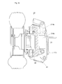
- a module is illustrated in Figures 1, 2a, 2b and 3, and includes a wheel, for example in the form of a tire (28) mounted so known on a rim (27).
- This rim is movable in rotation about an axis (d1) wheel, and is fixed by known means on a wheel spindle (25), for example by mounting radial bearings with axial stops.
- the rotation of the wheel can be braked or blocked by braking means, as a drum brake (26).
- a motor function is provided by a hydraulic motor (29) of a known type, mounted on the wheel spindle (25) and driving the rim in rotation.
- This hydraulic motor is supplied with fluid under pressure through flexible pipes (not shown) in from a hydraulic circuit pressurized by known means.
- Other types of motors or geared motors can be used, such as pneumatic or electric motors mounted directly inside each wheel module. Indeed, such hydraulic, pneumatic motors or electric are particularly advantageous because of their low footprint. Likewise, they are easy to control remotely and their energy connection can easily be done flexibly, by flexible pipes or electrical cables. These aspects greatly simplify their integration inside such a module with respect to a transmission mechanical from a centralized motor.
- a guiding function is ensured by a rotation of the rocket (25) of wheel relative to a fixed rocket (24), around a steering axis (d2) substantially vertical.
- This rotation is guided by pivoting of the rocket (25) wheel around two plain bearings comprising a pivot part (241, 242) and anti-friction cylindrical bearings (241a, 242a).
- the wheel spindle supports the fixed spindle, for example via an anti-friction pad (242b) into a centered horizontal annular disc on this same axis (d2).
- This rotation allowing the directing function is controlled by a force exerted on a part (251) of the wheel stub (25) not including the axle (d2) direction.
- This effort is applied by a steering link (32) by through a rocket ball joint (322) of known type, capable of transmitting forces passing through a point constituting its center of rotation while leaving free all rotations.
- the link (32) of steering is connected to a first part of a steering arm (33) by a similar ball joint, called arm ball joint (321).
- the first part of this arm (33) of steering is substantially parallel to the plane of rotation of the wheel, and is connected to the chassis (1) by a pivot link around a pin (331) with an axis substantially vertical.
- the steering arm (33) can be connected to an actuator of a known type, such as a jack (34), fixed to the frame (1).
- the steering arm (33) may include a second part substantially orthogonal to its first part.
- the jack (34) can then be positioned substantially along the axis of the chassis (1), and act on the steering arm through its second part by a pivot pin connection substantially vertical, for example a crankpin (334).
- a steering rod (31) can be connected by a pivot or ball joint (311) to this same steering arm, for example between its axis (331) of rotation and the point (321) of attachment of the rod (32) of management. If the steering rod is connected in the same way with the arm steering of another similar wheel module, the steering functions of these two wheel modules will then operate in a coordinated fashion.
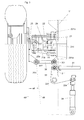
- a suspension function is performed by a set of elements of which a vertical section forms a deformable parallelogram.
- This parallelogram has two sides substantially vertical and parallel to each other, comprising on one side the rocket (24) fixed and on the other side a yoke (21) fixed to the chassis.
- Both other sides of this parallelogram consist of two arms (22, 23) of suspension substantially parallel to each other, one at the bottom and the other at the top, and whose angular position varies with the movement of the suspension.
- These arms of suspension are articulated on these first two sides, by pivot links along axes substantially horizontal and parallel to each other.
- the arm (22) lower suspension is thus articulated at one of its ends on the bottom of the yoke (21) and at its other end on the bottom of the fixed rocket (24), by example by pivoting around two alignments of two crankpins (221a, 221b, respectively 222a, 222b).
- the upper arm (23) of suspension is articulated at one of its ends on the top of the yoke (21) and at its other end on the top of the fixed rocket (24), for example by pivoting around two alignments of two crankpins (231 a, 231b, respectively 232a, 232b).
- Each suspension arm (22, 23) comprises itself two parallel bars joined together by a part (229, 239) horizontal.
- these bars have a hole which receives the pin participating in the pivot link.
- this horizontal part connecting the two bars of the upper arm can come into contact with a projecting part (219) integral with the yoke (1), thus producing a high stop comprising elastic means and / or depreciation.
- suspension leg (214) The movement of the suspension, i.e. the vertical deformation of this parallelogram, is controlled by the variation in length of an element telescopic, said suspension leg (214).
- this leg of suspension is fixed at its lower end to the fixed rocket (24) and to its high end to the yoke (21). This fixing is done by pivot connections substantially horizontal axes, for example by crank pins provided with anti-friction pads.
- the suspension strut comprises one or more actuators, for example example of hydraulic cylinders, the action of which controls the deformation of the suspension.
- This control can correspond to several effects. An effect can be to transmit part of the load from the chassis to the wheel, by limiting the deformation of the suspension. Another effect may be to cushion the oscillations of the chassis relative to the wheel by damping the deformation suspension. Another effect can be to modify or adjust the height of the chassis relative to the wheel, adjusting the length of the leg (214) by suspension.
- This suspension control can advantageously be carried out by the action of a pressurized fluid. It is indeed common to have a hydraulic pressure group on construction or handling equipment, this group being used to maneuver various handling appendages or to control certain functions of the machine.
- this leg comprises elastic means (not shown) of a known type thus enabling it to transmit to the rocket (24) fixes the load of the yoke (21), and therefore part of the load of the frame (1).
- this suspension leg (214) can also include damping means, for example a shock absorber hydraulic or gas, allowing it to absorb variations in the position of the suspension and decrease the vehicle's oscillations.
- the steering rod (32) can follow without deterioration of the deformation of the suspension by pivoting of its ball joints (321, 322) along horizontal axes.
- the pivot points of these same ball joints are arranged near the pivot axes of the articulations of one of the arms suspension, for example the joints (221, 222) of the lower arm (22) suspension.
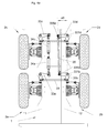
- the module wheel according to the invention is used to make two associated sets of wheels on the same chassis.
- a first wheel module (2a) is thus paired with a second wheel module (2b) to form a first set of wheels.
- a third module (2c) is paired with a fourth wheel module (2d) to form a second set of wheels.
- each wheel train the two modules are coupled in direction by a steering bar as described above.
- the command to each of the two trains is carried out by two cylinders (34a, 34c) as described above. Both trains can also be coupled in direction, by connecting with a drawbar (35), a steering arm of one train with a steering arm of the other train.
- the steering is obtained by a retraction of the jack (34a) controlling a module (2a) of one of the wheel sets, and by an extension of the jack (34c) controlling a module (3C) of the other wheel set.
- This action causes the arm (33a, 33c) for steering the corresponding modules.
- This pivoting of each controlled steering arm causes the arm to pivot simultaneously (33b, 33d) direction of the other module (2b, respectively 2d) of each train.
- the pivoting of the steering arm of each module then causes the steering of the wheel of each module.
- the steering drawbar (35) can for example be substantially in the chassis axis and connect the wheel modules located on the same side of the frame. This steering rod is then connected by a pivot link (335b, 335d), vertical axis, to the second part of the steering arm of each of these two wheel modules (2b, 2d).
- the two cylinders (34a, 34c) are then also in longitudinal position, fixed on a part of the frame (1) located between the two trains, and control the two modules (2a, 2c) located on the side opposite the steering drawbar (35).
- These two cylinders can then be connected by a pivot connection (334a, 334c), of vertical axis, to the second part of the arm direction of each of these two wheel modules (2a, 2c).
- Such coupling of two sets of wheels can allow for example ensure good coordination of their positions, or compensate for cylinder failures or inaccuracies.
- Such coupling between two trains can also strengthen the action of each cylinder by transmitting the force of the other cylinder, or allow the use of single acting cylinders or a single cylinder double-acting.
- This geometry is calculated for each train and provides values of lengths of steering rods (32) depending on the desired position for the turning center. These values are determined so that a direction control plane (d8) passing through both the axis (d2) of pivoting of the wheel knuckle (25) and through the center of the ball joint (322) controlling the pivoting forms a determined angle, called angle (a8), of steering control with the running surface of the wheel.
- the lengths of the steering rods of the modules (2c, 2d) of the second train and the geometry of the drawbar are determined for that the steering center of the second train is the same as the center of steering of the first train.
- This geometry is determined in particular by fixing the angle (a9) that forms with the axis (d0) of the chassis with a straight line (d9) passing through the center of the crankpins (335b, 335d) connecting the drawbar to the steering arm of a module (2b, 2d) of each of the two sets of wheels.
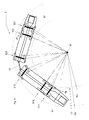
- a vehicle (5) comprises two half-vehicles (51, 52) opposite, articulated between them for example by a drawbar (53), and each provided with a cabin (510, 520) of conduct.
- Each of these half-vehicles (51, 52) comprises a chassis mounted on three sets of wheels (511, 512, 513 respectively 521, 522, 523) each comprising two wheel modules according to the invention.
- the vehicle can be driven from either of the two cabins, depending on needs and direction of travel. Driving can also be done from both cabins at the same time, for example in the case of complex or delicate maneuvers, each cabin then controlling the sets of wheels it includes.
- the six wheel sets are made up of wheel modules comprising a suspension function and a directing function. At least one of the six undercarriages have a driving function, preferably on both wheels.
- each of these trains (511, 512, 513, respectively 521, 522, 523) directors is carried out according to a sketch ensuring a steering where the axes of its wheels intersect in the same center turning.
- the two half-vehicles being articulated between them, their centers can be superimposed at the same point (c5).
- This the steering centers of the two cabins can be superimposed by electronic coordination of the steering of the steering trains of the two Half vehicles.
- One of the two cabins then orders its trains itself managers, for example by mechanical and hydraulic control, while the steering trains of the other cabin operate in a so-called self-steering mode.
- one (51) of the two half-vehicles comprises the energy systems, the other (52) using the systems carried by the first and does not comprising only two sets of wheels (521, 522).
- Each of the half vehicles (51, 52) comprises a load plate (541, 542) capable of receiving various prefabricated objects, devices, or elements, such as tunnel segments in concrete.
- an embodiment of a vehicle according to the invention can carry a load of the order of twice 20 tonnes, for a width of the order 2 m and a height of about 1.80 m.
- a vehicle (6) comprises two tractor half-vehicles (61, 62) of opposite pipes supporting the two ends of a structure (63) load-carrying unit, through articulated links pivoting around axes substantially vertical.
- Each of these half-vehicles (61, 62) comprises a control cabin (610, 620) and a chassis mounted on two trains (611, 612, respectively 621, 622) of wheels each comprising two wheel modules according to the invention.
- the vehicle can be driven from any of the two cabins, depending on needs and direction of travel.
- the driving can also be done from both cabins at the same time, each cabin then controlling the wheel sets which it comprises.
- the four wheel sets are made up of wheel modules comprising a suspension function. At least one of the four trains wheels has a driving function, preferably on its two wheels. All wheel sets have a guiding function.
- the trains (611, 612, respectively 621, 622) of wheels of each of the two cabs (61, respectively 62) are coupled together as described above to be able to turn in the same turning center (c61, respectively c62) for each of the cabins.
- Being able to steer trains from each cabin independently of each other thus allows the vehicle to follow a monotrace trajectory, located inside a width corridor (L61) little greater than the width of the vehicle itself. Due to the multiple joints of the vehicle, this trajectory can present changes of direction little spaced from the total length of the vehicle.
- the fact of steer the trains of the two cabins at the same time, in a rotation in opposite directions, also allows the vehicle to make a turn according to a particularly short turning radius.
- the turning trains from each of the two cabins can be controlled from the cabin which allows the operator to be in a good position to appreciate distances or avoid obstacles.
- the whole vehicle can be driven from a single cabin, called a cabin driving.
- the trains of one of the cabins, for example the leading cabin, are then ordered directly, while the trains in the other cabin operate in self-directing mode. That is to say that the deflection of these trains self-directing is calculated as and when to maintain their center steering on that of the trains of the steering half-vehicle, or in function other trajectory criteria, for example by servo means using sensors or encoders.
- the trains of each of the cabins are coupled to each other either by a drawbar as described higher, either by means of servo controlled in a way electronics or IT.
- the steering rods have a length adjustable by a device adjustable by the user. During a trip in crab, it is then possible to keep the wheels of the same train parallel between them, and therefore without any turning center.
- crab displacement position is just one example of the configurations and trajectories that a vehicle according to the invention.
- being able to turn each train of wheels independently of the others allows an infinity of trajectories without departing from the spirit of the invention.
- one (61) of the two half tractor units includes energy systems, the other (62) using systems carried by the former.
- Each of the half vehicles (61, 62) has a hinge which supports one end of a plate (64) of load capable of receiving various objects, devices, or prefabricated elements, such than a concrete mortar transport bucket.
- a realization of a vehicle according to the invention can carry a charge of the order of 25 tonnes, for a width of around 2 m and a height of around 1.80 m.
- a wheel module may include any combination of functions here described without departing from the spirit of the invention.
- a module can thus include for example a suspension function without directing function, as well only a directing function without a suspension function. Motor functions and braking can also be performed or not on any modules used for a machine or vehicle.
Landscapes
- Engineering & Computer Science (AREA)
- Mechanical Engineering (AREA)
- Chemical & Material Sciences (AREA)
- Combustion & Propulsion (AREA)
- Transportation (AREA)
- Vehicle Body Suspensions (AREA)
- Body Structure For Vehicles (AREA)
Abstract
Description
- la figure 1 représente une vue en coupe transversale d'un véhicule comportant un train de roues réalisé à partir de deux modules selon l'invention, dans une variante comportant suspension, direction et motricité ;
- les figures 2a et 2b représentent des vues partielles en coupe transversale selon l'axe de pivotement de direction, d'un module de roue selon l'invention dans deux positions différentes de suspension, dans une variante comportant suspension, direction et motricité (tringlerie de direction non représentée) ;
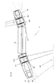
- la figure 3 représente une vue de dessus d'un module selon l'invention, incluant une demi-coupe au niveau de l'axe inférieur de la jambe de suspension, dans une variante comportant suspension, direction et motricité ;
- les figures 4a et 4b représentent une vue de dessus d'une partie de châssis utilisant deux trains de roues constitués de modules selon l'invention, le châssis étant figuré comme transparent, dans deux positions différentes de la direction, dans une variante comportant suspension, direction et motricité ;
- la figure 5 représente une vue schématique de dessus d'un véhicule selon l'invention en position de braquage, dans une configuration à deux demi-véhicules comportant chacun une cabine et trois trains directionnels ;
- les figures 6a et 6b représentent une vue schématique de dessus d'un véhicule selon l'invention, en position de virages sinueux et respectivement en position de déplacement latéral oblique ou « en crabe », dans une configuration à deux cabines pivotantes autour d'une partie porte-charge centrale, et comportant quatre trains directionnels ;
- la figure 7 représente une vue latérale en transparence d'un véhicule selon l'invention dans une configuration à deux cabines conduisant chacune une partie porte-charge, ces deux parties porte-charge étant reliées entre elles de façon articulée ;
- la figure 8 représente une vue latérale en transparence d'un véhicule selon l'invention dans une configuration à deux cabines pivotantes autour d'une partie porte-charge centrale.
Claims (21)
- Module de liaison au sol supportant tout ou partie d'un châssis (1) de véhicule ou engin spécial de chantier ou de manutention, ce module (2) comprenant une ou plusieurs roues permettant le déplacement de tout ou partie de ce véhicule, caractérisé en ce qu'au moins une de ces roues supporte une part du châssis par des moyens de liaison au sol commandés, disposés sur au moins un côté du châssis, occupant un volume (20) qui ne s'étend pas jusqu'à la partie (10) médiane du châssis selon l'axe (d1) de la roue et comportant la possibilité d'un déplacement de l'axe (d1) de la roue par rapport au châssis (1) assurant ainsi une fonction de suspension, indépendamment de la position ou de l'état des roues ou moyens de liaison au sol supportant ledit châssis et situés à l'extérieur de ce module (2) et indépendamment du déplacement de l'axe des roues des autres modules par rapport au châssis.
- Module selon l'une des revendications précédentes, caractérisé en ce que la roue est montée par une liaison pivot sur une fusée, dite fusée (25) de roue, cette fusée (25) de roue étant mobile en rotation par rapport au châssis selon un axe (d2) de direction formant avec la surface où s'appuie la roue un angle supérieur à 45°, la rotation de la fusée (25) de roue autour de cet axe de direction étant commandée par déplacement d'un élément, dit biellette (32) de direction, relié à la fusée de roue en un point décalé d'une certaine distance par rapport à l'axe (d2) de direction, cette rotation permettant au module d'assurer une fonction directrice.
- Module selon l'une des revendications précédentes, caractérisé en ce que la fusée (25) de roue est reliée au châssis (1) par l'intermédiaire d'une structure déformable, dite structure de suspension, apte à se déformer dans une direction verticale, ou perpendiculaire à la face du châssis portant le module, cette déformation se faisant selon la cinématique d'un parallélogramme de côtés rigides et de sommets d'angles variables, la biellette (32) de direction étant reliée à ses deux extrémités par des liaisons rotules lui permettant de rester sensiblement parallèle à l'un des côtés du parallélogramme.
- Module selon l'une des revendications précédentes, caractérisé en ce que la déformation de la structure déformable est commandée par la variation de longueur d'une jambe (214, 241') de suspension reliée à ses deux extrémités à deux éléments (21, 24) formant des côtés opposés du parallélogramme de déformation de cette structure déformable, cette jambe de suspension réalisant un contrôle de la hauteur de la suspension sous l'action éventuellement partielle d'un circuit de fluide sous pression.
- Module selon l'une des revendications précédentes, caractérisé en ce que la jambe de suspension réalise une fonction d'amortissement, de maintien de la hauteur, ou de réglage de la hauteur, ou une combinaison de ces fonctions.
- Module selon l'une des revendications précédentes, caractérisé en ce qu'il comprend un moteur entraínant en rotation la roue par rapport à la fusée (25) de roue autour de l'axe (d1) de roue.
- Module selon l'une des revendications précédentes, caractérisé en ce que le moteur fonctionne sous l'action d'un fluide sous pression ou d'un courant électrique.
- Véhicule en une ou plusieurs parties et comportant au moins un train de roues directrices composé d'au moins deux modules selon l'une des revendications précédentes, ces deux modules étant disposés de chaque côté du châssis et incluant une fonction directrice, caractérisé en ce que, dans au moins un des modules, le plan (d0) de roulement de la roue forme un angle, dit angle (a8) de commande de direction avec un plan (d8) de commande de direction, ce plan passant par l'axe (d2) de direction et le centre de rotation de la liaison (322) rotule reliant la fusée de roue et la biellette de direction, cet angle (a8) de commande de direction étant choisi pour que, lors du braquage d'un train, les axes (d1) des roues des modules d'un même train définissent un point déterminé, dit centre (c5, c6) de braquage, par l'intersection de leur projection verticale sur le sol.
- Véhicule selon la revendication 8, caractérisé en ce qu'au moins un module d'un train comporte une biellette (32) de direction reliée du côté du châssis à une extrémité d'un bras (33) de direction, ce bras de direction étant relié au châssis (1) par une liaison pivot (331) et étant commandé en rotation par un actionneur, le train comportant au moins une barre (31) de direction reliant le bras (33) de direction ou la biellette (33) de direction d'un module avec le bras de direction ou la biellette de direction d'un autre module du même train.
- Véhicule selon la revendication 11, caractérisé en ce qu'au moins un bras (33) de direction présente une forme en «L », l'intersection des branches supportant la liaison (331) au châssis (1), l'une des branches étant reliée à la biellette (32) de direction et à la barre (31) de direction, l'autre branche étant reliée à l'actionneur cet actionneur comprenant un vérin (34) formant avec l'axe longitudinal du châssis (1) un angle inférieur à 45°.
- Véhicule selon l'une des revendications 8 à 9, caractérisé en ce qu'il comporte plusieurs modules de roues directrices, au moins un de ces modules, dit autodirecteur, étant commandé en direction par un actionneur associé à des moyens de calcul et de commande aptes à coordonner le braquage de ce train en fonction de celui des autres trains du véhicule.
- Véhicule selon la revendication 10, caractérisé en ce qu'il comporte au moins un train autodirecteur dont le braquage est déterminé par les moyens de calcul et de commande de façon à ce que son centre (c5, c6) de braquage soit sensiblement superposé à celui d'au moins un autre train de roues directrices du véhicule.
- Véhicule selon l'une des revendications 8 à 12, caractérisé en ce qu'il comporte en une de ses extrémités au moins deux trains de roues directrices, une extrémité du bras (33) de direction d'un module (2b) étant reliée avec une extrémité du bras de direction d'un module (2d) d'un autre train par un timon (35) de direction, cette liaison assurant une coordination du braquage des deux trains.
- Véhicule selon la revendication 13, caractérisé en ce que le timon (35) de direction est relié aux bras (33b, 33d) de direction d'un module (2b, respectivement 2d) de chaque train en deux points (335b, respectivement 335d) définissant une droite formant un angle (a9) déterminé avec un plan incluant les axes des liaisons (331b, respectivement 331d) pivots reliant ces deux bras de direction au châssis (1), la valeur de cet angle (a9) pouvant être choisie pour que les centres de braquage des deux trains soient sensiblement superposés.
- Véhicule selon l'une des revendications 8 à 14, caractérisé en ce que le bras (33a) de direction d'au moins un module (2a, respectivement 2c) de chaque train est commandé par un actionneur (34a, respectivement 34c).
- Véhicule selon l'une des revendications 8 à 15, caractérisé en ce qu'il présente une forme allongée et comporte au moins deux trains (511, 512, respectivement 521, 522) de roues directrices situés de chaque côté du centre de gravité du véhicule, le braquage de ces trains étant commandé et coordonné par des moyens de commande de façon à ce que les directions (dg, dd) imprimées au châssis par ces deux trains soient dirigées de deux côtés opposés du châssis, cette coordination de braquage de ces trains permettant ainsi un braquage du véhicule selon un faible rayon (r5, r6) de braquage.
- Véhicule selon l'une des revendications 8 à 16, caractérisé en ce qu'il présente une forme allongée et comporte au moins deux trains (611, 612, respectivement 621, 622) de roues directrices situés de chaque côté du centre de gravité du véhicule, le braquage de ces trains étant commandé et coordonné par des moyens de commande de façon à ce que les directions (dg1, dg2) imprimées au châssis par ces deux trains soient dirigées du même côté du châssis, cette coordination de braquage de ces trains permettant ainsi un déplacement de l'ensemble du véhicule « en crabe », c'est à dire dans une direction (dg1, dg2) incluant une composante (dlat1, dlat2) latérale par rapport au véhicule.
- Véhicule selon l'une des revendications 8 à 17, caractérisé en ce qu'il comporte au moins deux cabines (510, 520, respectivement 610, 620) ou postes de commandes, chacune de ces cabines comportant des moyens de commande de l'ensemble des modules de roues du véhicule.
- Véhicule selon l'une des revendications 8 à 17, caractérisé en ce qu'il comporte au moins deux cabines ou postes de commandes, chacune de ces cabines étant apte à commander séparément une partie des modules ou trains de roues du véhicule.
- Véhicule selon l'une des revendications 8 à 19, caractérisé en ce qu'il comporte deux demi-véhicules (51, 52) dos à dos, articulés entre eux directement ou par l'intermédiaire d'un timon (53), chaque demi-véhicule comportant un plateau (541, respectivement 542) de charge, dont la surface de charge est située au-dessous de l'axe (d1) des roues, et une cabine (510, respectivement 520) de commande et étant supportée par au moins un train (511, 512, respectivement 521, 522) de roues directrices du côté de sa cabine et par au moins un train de roues non directrices (513, respectivement 523) du côté de l'articulation.
- Véhicule selon l'une des revendications 8 à 20, caractérisé en ce qu'il comporte deux demi-véhicules tracteur (61, 62) dos à dos et supportant chacun une extrémité d'une partie de charge (64) par une articulation, chaque demi-véhicule comportant une partie (541, respectivement 542) de plateau de charge, dont la surface de charge est située au-dessous de l'axe (d1) des roues, et une cabine (510, respectivement 520) de commande et étant supporté par au moins un train (511, 512, respectivement 521, 522) de roues directrices et au moins un train de roues non directrices (513, respectivement 523).
Applications Claiming Priority (2)
| Application Number | Priority Date | Filing Date | Title |
|---|---|---|---|
| FR0202569A FR2836419B1 (fr) | 2002-02-28 | 2002-02-28 | Module de roue independant et vehicule utilisant ce module |
| FR0202569 | 2002-02-28 |
Publications (2)
| Publication Number | Publication Date |
|---|---|
| EP1340670A1 true EP1340670A1 (fr) | 2003-09-03 |
| EP1340670B1 EP1340670B1 (fr) | 2007-01-03 |
Family
ID=27676187
Family Applications (1)
| Application Number | Title | Priority Date | Filing Date |
|---|---|---|---|
| EP20030290356 Expired - Lifetime EP1340670B1 (fr) | 2002-02-28 | 2003-02-14 | Module de roue indépendant et véhicule utilisant ce module |
Country Status (3)
| Country | Link |
|---|---|
| EP (1) | EP1340670B1 (fr) |
| DE (1) | DE60310787T2 (fr) |
| FR (1) | FR2836419B1 (fr) |
Cited By (9)
| Publication number | Priority date | Publication date | Assignee | Title |
|---|---|---|---|---|
| EP1985474A3 (fr) * | 2007-04-25 | 2010-02-10 | Doll Fahrzeugbau AG | Semi-remorque |
| RU2420421C2 (ru) * | 2009-04-20 | 2011-06-10 | Феликс Аронович Черняков | Способ гидроусиления дистанционного рулевого управления и система рулевого управления для его осуществления |
| CN102501897A (zh) * | 2011-10-29 | 2012-06-20 | 郑州宇通客车股份有限公司 | 随动转向机构及使用该转向机构的独立悬架支撑桥 |
| WO2014202693A1 (fr) | 2013-06-19 | 2014-12-24 | Techni-Metal Systemes | Module de liaison au sol et véhicule utilisant au moins un module de liaison au sol |
| EP3176125A1 (fr) * | 2015-12-03 | 2017-06-07 | The Raymond Corporation | Système et méthode pour un chariot de manutention avec une suspension de sol |
| CN110758556A (zh) * | 2019-11-26 | 2020-02-07 | 宜昌天工智能机械股份有限公司 | 一种轮式农机前后轮同辙控制机构 |
| CN114056088A (zh) * | 2021-08-05 | 2022-02-18 | 山东奥尼司特机械有限公司 | 一种兼具独立转向和独立驱动功能的底盘总成 |
| CN114872788A (zh) * | 2022-04-08 | 2022-08-09 | 江苏大学 | 一种移动底盘及其控制方法和移动机器人 |
| CN116209614A (zh) * | 2020-09-09 | 2023-06-02 | 舍弗勒技术股份两合公司 | 用于机动车辆的车轮模块 |
Families Citing this family (5)
| Publication number | Priority date | Publication date | Assignee | Title |
|---|---|---|---|---|
| US8308174B2 (en) | 2007-06-04 | 2012-11-13 | Continental Teves Ag & Ohg | Steering device for adjusting a wheel steering angle |
| FR2971761B1 (fr) * | 2011-02-23 | 2013-02-15 | Metalliance | Train de vehicules de transport a fonctionnement reversible |
| CN103043099A (zh) * | 2013-01-30 | 2013-04-17 | 安徽合力股份有限公司 | 双向四轴线式转向平板拖车 |
| FR3071813B1 (fr) * | 2017-10-03 | 2019-11-01 | Commissariat A L'energie Atomique Et Aux Energies Alternatives | Vehicule automobile routier attelable a suspension et direction compacte |
| JP2024530228A (ja) * | 2021-08-16 | 2024-08-16 | リー・オートモーティブ・リミテッド | 横方向サスペンションを備えたデュアルホイールコーナーシステム |
Citations (6)
| Publication number | Priority date | Publication date | Assignee | Title |
|---|---|---|---|---|
| US3302739A (en) * | 1963-11-19 | 1967-02-07 | Goodman Mfg Co | Shuttle cars with six driven wheels |
| US3314690A (en) * | 1963-11-19 | 1967-04-18 | Westinghouse Air Brake Co | Steering mechanism for haulage vehicles |
| FR1497349A (fr) * | 1966-10-22 | 1967-10-06 | Caterpillar Tractor Co | Mécanisme de direction pour véhicules à deux tracteurs |
| DE3616457C1 (en) * | 1986-05-15 | 1987-11-26 | Schultz Rainer M Dipl Ing | Track-free, two-component vehicle train |
| DE4110638A1 (de) * | 1991-04-02 | 1992-10-08 | Klaue Hermann | Elektrischer radnabenantrieb fuer kraftfahrzeuge |
| EP0870671A2 (fr) * | 1997-04-08 | 1998-10-14 | Kidde Industries, Inc. | Système de direction pour véhicule à essieux multiples |
-
2002
- 2002-02-28 FR FR0202569A patent/FR2836419B1/fr not_active Expired - Fee Related
-
2003
- 2003-02-14 EP EP20030290356 patent/EP1340670B1/fr not_active Expired - Lifetime
- 2003-02-14 DE DE2003610787 patent/DE60310787T2/de not_active Expired - Lifetime
Patent Citations (6)
| Publication number | Priority date | Publication date | Assignee | Title |
|---|---|---|---|---|
| US3302739A (en) * | 1963-11-19 | 1967-02-07 | Goodman Mfg Co | Shuttle cars with six driven wheels |
| US3314690A (en) * | 1963-11-19 | 1967-04-18 | Westinghouse Air Brake Co | Steering mechanism for haulage vehicles |
| FR1497349A (fr) * | 1966-10-22 | 1967-10-06 | Caterpillar Tractor Co | Mécanisme de direction pour véhicules à deux tracteurs |
| DE3616457C1 (en) * | 1986-05-15 | 1987-11-26 | Schultz Rainer M Dipl Ing | Track-free, two-component vehicle train |
| DE4110638A1 (de) * | 1991-04-02 | 1992-10-08 | Klaue Hermann | Elektrischer radnabenantrieb fuer kraftfahrzeuge |
| EP0870671A2 (fr) * | 1997-04-08 | 1998-10-14 | Kidde Industries, Inc. | Système de direction pour véhicule à essieux multiples |
Cited By (18)
| Publication number | Priority date | Publication date | Assignee | Title |
|---|---|---|---|---|
| EP1985474A3 (fr) * | 2007-04-25 | 2010-02-10 | Doll Fahrzeugbau AG | Semi-remorque |
| DE202008017914U1 (de) | 2007-04-25 | 2010-10-28 | Doll Fahrzeugbau Ag | Sattelauflieger |
| RU2420421C2 (ru) * | 2009-04-20 | 2011-06-10 | Феликс Аронович Черняков | Способ гидроусиления дистанционного рулевого управления и система рулевого управления для его осуществления |
| CN102501897A (zh) * | 2011-10-29 | 2012-06-20 | 郑州宇通客车股份有限公司 | 随动转向机构及使用该转向机构的独立悬架支撑桥 |
| WO2014202693A1 (fr) | 2013-06-19 | 2014-12-24 | Techni-Metal Systemes | Module de liaison au sol et véhicule utilisant au moins un module de liaison au sol |
| FR3007328A1 (fr) * | 2013-06-19 | 2014-12-26 | Techni Metal Systemes | Module de liaison au sol et vehicule utilisant au moins un module de liaison au sol |
| US10294089B2 (en) | 2015-12-03 | 2019-05-21 | The Raymond Corporation | Systems and methods for a material handling vehicle with a floor suspension |
| CN106829802A (zh) * | 2015-12-03 | 2017-06-13 | 雷蒙德股份有限公司 | 用于具有底板悬架的物料搬运车辆的系统和方法 |
| EP3176125A1 (fr) * | 2015-12-03 | 2017-06-07 | The Raymond Corporation | Système et méthode pour un chariot de manutention avec une suspension de sol |
| CN106829802B (zh) * | 2015-12-03 | 2019-11-05 | 雷蒙德股份有限公司 | 用于具有底板悬架的物料搬运车辆的系统和方法 |
| CN110758556A (zh) * | 2019-11-26 | 2020-02-07 | 宜昌天工智能机械股份有限公司 | 一种轮式农机前后轮同辙控制机构 |
| CN116209614A (zh) * | 2020-09-09 | 2023-06-02 | 舍弗勒技术股份两合公司 | 用于机动车辆的车轮模块 |
| US20230322299A1 (en) * | 2020-09-09 | 2023-10-12 | Schaeffler Technologies AG & Co. KG | Wheel module for a motor vehicle |
| CN116209614B (zh) * | 2020-09-09 | 2026-04-21 | 舍弗勒技术股份两合公司 | 用于机动车辆的车轮模块 |
| CN114056088A (zh) * | 2021-08-05 | 2022-02-18 | 山东奥尼司特机械有限公司 | 一种兼具独立转向和独立驱动功能的底盘总成 |
| CN114056088B (zh) * | 2021-08-05 | 2024-04-02 | 山东奥尼司特机械有限公司 | 一种兼具独立转向和独立驱动功能的底盘总成 |
| CN114872788A (zh) * | 2022-04-08 | 2022-08-09 | 江苏大学 | 一种移动底盘及其控制方法和移动机器人 |
| CN114872788B (zh) * | 2022-04-08 | 2023-12-05 | 江苏大学 | 一种移动底盘及其控制方法和移动机器人 |
Also Published As
| Publication number | Publication date |
|---|---|
| FR2836419A1 (fr) | 2003-08-29 |
| DE60310787T2 (de) | 2007-10-11 |
| FR2836419B1 (fr) | 2005-02-18 |
| EP1340670B1 (fr) | 2007-01-03 |
| DE60310787D1 (de) | 2007-02-15 |
Similar Documents
| Publication | Publication Date | Title |
|---|---|---|
| EP1340670B1 (fr) | Module de roue indépendant et véhicule utilisant ce module | |
| CA2160992C (fr) | Vehicule forme d'une suite de modules relies entre eux par une liaison composite articulee | |
| CA2879172C (fr) | Essieu et vehicule comprenant au moins un tel essieu | |
| FI125426B (fi) | Sovitelma ja menetelmä ajoneuvon teli- tai tela-akselin ja rungon välisen kiertoliikkeen mahdollistamiseksi | |
| CN106828633B (zh) | 一种电动履带式全地形底盘 | |
| EP3318430B1 (fr) | Tracteur enjambeur | |
| EP2994370B1 (fr) | Châssis de support de charge et véhicule doté d'un châssis de support de charge | |
| EP2374635B1 (fr) | Système d'essieu, module d'essieu comprenant au moins un tel système d'essieu et véhicule comprenant au moins un tel module | |
| JPH11502481A (ja) | 大型ダンプトラックサスペンション | |
| EP3010733A1 (fr) | Module de liaison au sol et véhicule utilisant au moins un module de liaison au sol | |
| EP1507452B1 (fr) | Vehicule inclinable | |
| EP3093217A1 (fr) | Jeu de roues orientables et véhicule équipé avec celui-ci | |
| FR2652313A1 (fr) | Vehicule elementaire a deux roues independantes et vehicule complexe comportant au moins un tel vehicule elementaire. | |
| EP3744615A1 (fr) | Véhicule routier attelable comportant des dispositifs d articulation avant et arrière | |
| EP2492170B1 (fr) | Train de véhicules de transport à fonctionnement réversible | |
| EP2994363B1 (fr) | Dispositif de direction et véhicule articulé pourvu du dispositif de direction | |
| CN102019959A (zh) | 转向机构及具有该转向机构的全挂车 | |
| CA3035144C (fr) | Ensemble et procede permettant un mouvement de rotation dans un vehicule ou une machine de travail mobile | |
| FR3015915B1 (fr) | Chassis de vehicule omnidirectionnel comportant des corps de chassis deplacables l'un par rapport a l'autre | |
| CN116691827A (zh) | 一种具有全地形适应能力的可变构态四轮全驱移动平台 | |
| FR2980398A1 (fr) | Dispositif de suspension d'une roue, et vehicule muni d'au moins une roue equipee d'un tel dispositif de suspension | |
| CA2814791A1 (fr) | Dispositif de braquage angulaire a correction progressive, systemes et ensembles correspondants, procedes de fabrication et utilisations correspondantes | |
| CN224105455U (zh) | 一种带有臂车式转向结构的小车底盘 | |
| FR2675105A1 (fr) | Train de roulement pour vehicule circulant sur une voie de guidage. | |
| CN217917514U (zh) | 一种麦轮轮组 |
Legal Events
| Date | Code | Title | Description |
|---|---|---|---|
| PUAI | Public reference made under article 153(3) epc to a published international application that has entered the european phase |
Free format text: ORIGINAL CODE: 0009012 |
|
| AK | Designated contracting states |
Kind code of ref document: A1 Designated state(s): AT BE BG CH CY CZ DE DK EE ES FI FR GB GR HU IE IT LI LU MC NL PT SE SI SK TR |
|
| AX | Request for extension of the european patent |
Extension state: AL LT LV MK RO |
|
| 17P | Request for examination filed |
Effective date: 20031013 |
|
| AKX | Designation fees paid |
Designated state(s): DE ES FR GB IT |
|
| GRAP | Despatch of communication of intention to grant a patent |
Free format text: ORIGINAL CODE: EPIDOSNIGR1 |
|
| GRAS | Grant fee paid |
Free format text: ORIGINAL CODE: EPIDOSNIGR3 |
|
| GRAA | (expected) grant |
Free format text: ORIGINAL CODE: 0009210 |
|
| AK | Designated contracting states |
Kind code of ref document: B1 Designated state(s): DE ES FR GB IT |
|
| REG | Reference to a national code |
Ref country code: GB Ref legal event code: FG4D Free format text: NOT ENGLISH |
|
| REF | Corresponds to: |
Ref document number: 60310787 Country of ref document: DE Date of ref document: 20070215 Kind code of ref document: P |
|
| PG25 | Lapsed in a contracting state [announced via postgrant information from national office to epo] |
Ref country code: ES Free format text: LAPSE BECAUSE OF FAILURE TO SUBMIT A TRANSLATION OF THE DESCRIPTION OR TO PAY THE FEE WITHIN THE PRESCRIBED TIME-LIMIT Effective date: 20070414 |
|
| GBV | Gb: ep patent (uk) treated as always having been void in accordance with gb section 77(7)/1977 [no translation filed] |
Effective date: 20070103 |
|
| PLBE | No opposition filed within time limit |
Free format text: ORIGINAL CODE: 0009261 |
|
| STAA | Information on the status of an ep patent application or granted ep patent |
Free format text: STATUS: NO OPPOSITION FILED WITHIN TIME LIMIT |
|
| PG25 | Lapsed in a contracting state [announced via postgrant information from national office to epo] |
Ref country code: GB Free format text: LAPSE BECAUSE OF FAILURE TO SUBMIT A TRANSLATION OF THE DESCRIPTION OR TO PAY THE FEE WITHIN THE PRESCRIBED TIME-LIMIT Effective date: 20070103 |
|
| 26N | No opposition filed |
Effective date: 20071005 |
|
| REG | Reference to a national code |
Ref country code: FR Ref legal event code: PLFP Year of fee payment: 14 |
|
| REG | Reference to a national code |
Ref country code: FR Ref legal event code: PLFP Year of fee payment: 15 |
|
| REG | Reference to a national code |
Ref country code: FR Ref legal event code: PLFP Year of fee payment: 16 |
|
| PGFP | Annual fee paid to national office [announced via postgrant information from national office to epo] |
Ref country code: DE Payment date: 20220225 Year of fee payment: 20 |
|
| PGFP | Annual fee paid to national office [announced via postgrant information from national office to epo] |
Ref country code: IT Payment date: 20220222 Year of fee payment: 20 Ref country code: FR Payment date: 20220221 Year of fee payment: 20 |
|
| REG | Reference to a national code |
Ref country code: DE Ref legal event code: R071 Ref document number: 60310787 Country of ref document: DE |