EP1340670A1 - Independent wheel module and vehicle using such a module - Google Patents
Independent wheel module and vehicle using such a module Download PDFInfo
- Publication number
- EP1340670A1 EP1340670A1 EP03290356A EP03290356A EP1340670A1 EP 1340670 A1 EP1340670 A1 EP 1340670A1 EP 03290356 A EP03290356 A EP 03290356A EP 03290356 A EP03290356 A EP 03290356A EP 1340670 A1 EP1340670 A1 EP 1340670A1
- Authority
- EP
- European Patent Office
- Prior art keywords
- steering
- vehicle
- chassis
- wheel
- module
- Prior art date
- Legal status (The legal status is an assumption and is not a legal conclusion. Google has not performed a legal analysis and makes no representation as to the accuracy of the status listed.)
- Granted
Links
Images


Classifications
-
- B—PERFORMING OPERATIONS; TRANSPORTING
- B62—LAND VEHICLES FOR TRAVELLING OTHERWISE THAN ON RAILS
- B62D—MOTOR VEHICLES; TRAILERS
- B62D7/00—Steering linkage; Stub axles or their mountings
- B62D7/06—Steering linkage; Stub axles or their mountings for individually-pivoted wheels, e.g. on king-pins
-
- B—PERFORMING OPERATIONS; TRANSPORTING
- B60—VEHICLES IN GENERAL
- B60G—VEHICLE SUSPENSION ARRANGEMENTS
- B60G3/00—Resilient suspensions for a single wheel
- B60G3/18—Resilient suspensions for a single wheel with two or more pivoted arms, e.g. parallelogram
- B60G3/20—Resilient suspensions for a single wheel with two or more pivoted arms, e.g. parallelogram all arms being rigid
-
- B—PERFORMING OPERATIONS; TRANSPORTING
- B62—LAND VEHICLES FOR TRAVELLING OTHERWISE THAN ON RAILS
- B62D—MOTOR VEHICLES; TRAILERS
- B62D53/00—Tractor-trailer combinations; Road trains
- B62D53/005—Combinations with at least three axles and comprising two or more articulated parts
-
- B—PERFORMING OPERATIONS; TRANSPORTING
- B62—LAND VEHICLES FOR TRAVELLING OTHERWISE THAN ON RAILS
- B62D—MOTOR VEHICLES; TRAILERS
- B62D7/00—Steering linkage; Stub axles or their mountings
- B62D7/06—Steering linkage; Stub axles or their mountings for individually-pivoted wheels, e.g. on king-pins
- B62D7/14—Steering linkage; Stub axles or their mountings for individually-pivoted wheels, e.g. on king-pins the pivotal axes being situated in more than one plane transverse to the longitudinal centre line of the vehicle, e.g. all-wheel steering
- B62D7/142—Steering linkage; Stub axles or their mountings for individually-pivoted wheels, e.g. on king-pins the pivotal axes being situated in more than one plane transverse to the longitudinal centre line of the vehicle, e.g. all-wheel steering specially adapted for particular vehicles, e.g. tractors, carts, earth-moving vehicles, trucks
-
- B—PERFORMING OPERATIONS; TRANSPORTING
- B62—LAND VEHICLES FOR TRAVELLING OTHERWISE THAN ON RAILS
- B62D—MOTOR VEHICLES; TRAILERS
- B62D7/00—Steering linkage; Stub axles or their mountings
- B62D7/06—Steering linkage; Stub axles or their mountings for individually-pivoted wheels, e.g. on king-pins
- B62D7/14—Steering linkage; Stub axles or their mountings for individually-pivoted wheels, e.g. on king-pins the pivotal axes being situated in more than one plane transverse to the longitudinal centre line of the vehicle, e.g. all-wheel steering
- B62D7/15—Steering linkage; Stub axles or their mountings for individually-pivoted wheels, e.g. on king-pins the pivotal axes being situated in more than one plane transverse to the longitudinal centre line of the vehicle, e.g. all-wheel steering characterised by means varying the ratio between the steering angles of the steered wheels
- B62D7/1509—Steering linkage; Stub axles or their mountings for individually-pivoted wheels, e.g. on king-pins the pivotal axes being situated in more than one plane transverse to the longitudinal centre line of the vehicle, e.g. all-wheel steering characterised by means varying the ratio between the steering angles of the steered wheels with different steering modes, e.g. crab-steering, or steering specially adapted for reversing of the vehicle
-
- B—PERFORMING OPERATIONS; TRANSPORTING
- B60—VEHICLES IN GENERAL
- B60G—VEHICLE SUSPENSION ARRANGEMENTS
- B60G2200/00—Indexing codes relating to suspension types
- B60G2200/10—Independent suspensions
- B60G2200/14—Independent suspensions with lateral arms
- B60G2200/144—Independent suspensions with lateral arms with two lateral arms forming a parallelogram
-
- B—PERFORMING OPERATIONS; TRANSPORTING
- B60—VEHICLES IN GENERAL
- B60G—VEHICLE SUSPENSION ARRANGEMENTS
- B60G2200/00—Indexing codes relating to suspension types
- B60G2200/40—Indexing codes relating to the wheels in the suspensions
- B60G2200/44—Indexing codes relating to the wheels in the suspensions steerable
-
- B—PERFORMING OPERATIONS; TRANSPORTING
- B60—VEHICLES IN GENERAL
- B60G—VEHICLE SUSPENSION ARRANGEMENTS
- B60G2206/00—Indexing codes related to the manufacturing of suspensions: constructional features, the materials used, procedures or tools
- B60G2206/01—Constructional features of suspension elements, e.g. arms, dampers, springs
- B60G2206/011—Modular constructions
- B60G2206/0112—Bogies for heavy vehicles
-
- B—PERFORMING OPERATIONS; TRANSPORTING
- B60—VEHICLES IN GENERAL
- B60G—VEHICLE SUSPENSION ARRANGEMENTS
- B60G2206/00—Indexing codes related to the manufacturing of suspensions: constructional features, the materials used, procedures or tools
- B60G2206/01—Constructional features of suspension elements, e.g. arms, dampers, springs
- B60G2206/011—Modular constructions
- B60G2206/0114—Independent suspensions on subframes
-
- B—PERFORMING OPERATIONS; TRANSPORTING
- B60—VEHICLES IN GENERAL
- B60G—VEHICLE SUSPENSION ARRANGEMENTS
- B60G2300/00—Indexing codes relating to the type of vehicle
- B60G2300/02—Trucks; Load vehicles
- B60G2300/026—Heavy duty trucks
-
- B—PERFORMING OPERATIONS; TRANSPORTING
- B60—VEHICLES IN GENERAL
- B60G—VEHICLE SUSPENSION ARRANGEMENTS
- B60G2300/00—Indexing codes relating to the type of vehicle
- B60G2300/04—Trailers
-
- B—PERFORMING OPERATIONS; TRANSPORTING
- B60—VEHICLES IN GENERAL
- B60G—VEHICLE SUSPENSION ARRANGEMENTS
- B60G2300/00—Indexing codes relating to the type of vehicle
- B60G2300/14—Buses
-
- B—PERFORMING OPERATIONS; TRANSPORTING
- B60—VEHICLES IN GENERAL
- B60G—VEHICLE SUSPENSION ARRANGEMENTS
- B60G2300/00—Indexing codes relating to the type of vehicle
- B60G2300/38—Low or lowerable bed vehicles
Definitions
- the present invention relates to a wheel module used for construction of a special site or handling machine or vehicle, as well as such a machine or vehicle.
- such devices are often produced in very small series or on order, and are built from a chassis supported by one or more sets of wheels.
- a wheel set is usually designed as a bridge arranged under a frame and supporting a part of this chassis.
- a bridge arranged under a frame and supporting a part of this chassis.
- We can define such a bridge as a set of several wheels distributed on both sides of the chassis, and carried by a structure itself movable relative to the chassis, for example comprising a unsprung axle passing under the chassis.
- This structure may include drive elements for drive wheels, and directions for steered wheels.
- This bridge is thus positioned under the chassis, most often by means of elastic elements and elements shock absorbers, so as to produce a suspension avoiding transmitting to the chassis all the irregularities of the ground during the rolling.
- One of the aims of the invention is thus to propose a connection device on the ground by wheel making it possible to produce a set of wheels supporting a chassis positioned as low as possible.
- Another object of the invention is to propose a vehicle using such a wheel device.
- One of the aims of the invention is thus to propose a vehicle whose several sets of wheels are steering, in parallel or in opposition between them.
- a ground connection module supporting all or part of a vehicle chassis or special construction or handling equipment, this module comprising one or more wheels allowing the movement of all or part of this vehicle, characterized in that at least one of these wheels supports part of the chassis by controlled ground connection means, arranged on at least one side of the chassis, occupying a volume which does not extend not to the middle part of the chassis along the axis of the wheel, and comprising the possibility of a displacement of the axis of the wheel relative to the chassis thus ensuring a suspension function, regardless of the position or the condition of the wheels or ground connection means supporting said chassis and located outside of this module and independently of the axis movement wheels of the other modules in relation to the chassis.
- the wheel is mounted by a pivot link on a rocket, called wheel rocket, this wheel rocket being movable in rotation by relation to the chassis along a direction axis forming with the surface where the wheel leans an angle greater than 45 °, the rotation of the wheel spindle around of this steering axis being controlled by displacement of an element, called steering rod, connected to the wheel stub at a point offset by a certain distance from the steering axis, this rotation allowing the module to provide a guiding function.
- a rocket called wheel rocket
- the wheel spindle is connected to the chassis by through a deformable structure, called suspension structure, suitable for deform in a vertical direction, or perpendicular to the face of the chassis carrying the module, this deformation taking place according to the kinematics of a parallelogram of rigid sides and vertices of variable angles, the steering rod being connected at its two ends by ball joints allowing it to remain substantially parallel to one of the sides of the parallelogram.
- suspension structure suitable for deform in a vertical direction, or perpendicular to the face of the chassis carrying the module
- the deformation of the deformable structure is controlled by the variation in length of a suspension strut connected to its two ends with two elements forming opposite sides of the deformation parallelogram of this deformable structure, this leg of suspension carrying out a control of the height of the suspension under the action possibly partial of a pressurized fluid circuit.
- the suspension strut performs a function cushioning, maintaining the height, or adjusting the height, or a combination of these functions.
- the module comprises a motor driving in rotation of the wheel with respect to the wheel spindle around the wheel axle.
- the engine operates under the action of a fluid under pressure or electric current.
- One of the aims of the invention is thus to propose a vehicle whose several sets of wheels are steering, in parallel or in opposition between them.
- a vehicle in one or more parts and comprising at least one set of steered wheels composed of at least two modules according to one of the preceding claims, these two modules being arranged on each side of the chassis and including a directing function, characterized in that, in at least one of the modules, the running surface of the wheel forms an angle, called the steering control angle with a plane of steering control, this plane passing through the steering axis and the center of rotation of the ball joint connecting the wheel stub and the steering rod, this steering control angle being chosen so that, when turning of a train, the axes of the wheels of the modules of the same train define a determined point, called turning center, by the intersection of their projection vertical on the ground.
- At least one module of a train comprises a steering rod connected to the chassis side at one end of an arm steering, this steering arm being connected to the chassis by a pivot link and being controlled in rotation by an actuator, the train comprising at least a steering rod connecting the steering arm or the steering rod of a module with the steering arm or steering rod of another module on the same train.
- At least one steering arm has a "L" shape, the intersection of the branches supporting the connection to the chassis, one of the branches being connected to the steering rod and to the steering, the other branch being connected to the actuator, this actuator comprising a cylinder forming with the longitudinal axis of the chassis an angle less than 45 °.
- the vehicle comprises several modules of steered wheels, at least one of these modules, called seeker, being controlled in direction by an actuator associated with calculation means and control capable of coordinating the deflection of this train according to that other trains in the vehicle.
- the vehicle comprises at least one train seeker whose steering is determined by the means of calculation and controls so that its turning center is substantially superimposed on that of at least one other set of steered wheels of the vehicle.
- the vehicle has at one of its ends at least two sets of steered wheels, one end of the steering arm of a module being connected with one end of the steering arm of a module another train by a drawbar, this link ensuring a coordination of the steering of the two trains.
- the steering drawbar is connected to the arms of direction of a module of each train at two points defining a straight line forming a determined angle with a plane including the axes of the pivot connections connecting these two steering arms to the chassis, the value of this angle possibly be chosen so that the turning centers of the two trains are substantially superimposed.
- the steering arm of at least one module each train is controlled by an actuator.
- the vehicle has an elongated shape and has at least two sets of steered wheels located on each side of the center of gravity of the vehicle, the steering of these trains being controlled and coordinated by control means so that the directions printed on the chassis by these two trains are directed from two sides opposite of the chassis, this steering coordination of these trains allowing thus a turning of the vehicle according to a small turning radius.
- the vehicle has an elongated shape and has at least two sets of steered wheels located on each side of the center of gravity of the vehicle, the steering of these trains being controlled and coordinated by control means so that the directions printed on the chassis by these two trains are directed on the same side of the chassis, this steering coordination of these trains thus allowing a movement of the whole vehicle "in crab", that is to say in a steering including a lateral component with respect to the vehicle.
- the vehicle comprises at least two cabins or control stations, each of these cabins comprising means of control of all vehicle wheel modules.
- the vehicle comprises at least two cabins or control stations, each of these cabins being able to control separately a part of the vehicle modules or wheel sets.
- the vehicle comprises two back half-vehicles backpack, hinged together directly or by means of a drawbar, each half-vehicle with a load plate, the load surface of which is located below the wheel center line, and a control cabin and being supported by at least one set of steered wheels on the side of its cabin and by at least one set of non-steerable wheels on the side of the joint.
- the vehicle comprises two half-vehicles tractor back to back and each supporting one end of a load part by an articulation, each half-vehicle comprising a plate portion of load, the load surface of which is located below the wheel center line, and a control cabin and being supported by at least one set of wheels steerable and at least one set of non-steerable wheels.
- the wheel modules are presented as used in pairs to form wheel sets. Without leaving the spirit of the invention, it is of course entirely possible to also use such modules in odd numbers. In the same way, it is also possible to use such modules without being paired in wheel sets, for example example staggered on both sides of the vehicle. he is also it is possible to have several wheels coupled in the same module, by example to increase load capacities or improve maintenance or security. It is also possible to use such wheel modules for supporting a frame or part of a frame having a different shape of the classic elongated chassis. Special vehicles articulated in several parts, or chassis of various shapes, for example square, can thus use such wheel modules without departing from the spirit of the invention.
- a vehicle according to the invention rests on wheel modules fixed directly to its chassis, for example on the side of the frame.
- Such an arrangement allows the chassis to be lowered very low, by example up to the limit of the ground clearance of the vehicle or at the height of the axis wheels, without having to leave space under the chassis for the travel of an unsprung axle.
- the vehicle according to the invention thus comprises a chassis (1) comprising for example a box or two longitudinal beams (11, 12) with an “I” profile.
- the wheel modules (2) are thus fixed on the chassis and occupy a space (20) which does not extend to the middle part (10) of this chassis.
- this middle part is of course understood to be located in the middle of the distance between these two wheels or wheel modules and down to a height at least less than that of the wheel center line.
- this middle part can then naturally be interpreted to each module as being a part of the vehicle supported inter alia by this module, this part including the axis of the module wheel.
- each module has a function of suspension, a steering function, a braking function, and a function driving.
- a module is illustrated in Figures 1, 2a, 2b and 3, and includes a wheel, for example in the form of a tire (28) mounted so known on a rim (27).
- This rim is movable in rotation about an axis (d1) wheel, and is fixed by known means on a wheel spindle (25), for example by mounting radial bearings with axial stops.
- the rotation of the wheel can be braked or blocked by braking means, as a drum brake (26).
- a motor function is provided by a hydraulic motor (29) of a known type, mounted on the wheel spindle (25) and driving the rim in rotation.
- This hydraulic motor is supplied with fluid under pressure through flexible pipes (not shown) in from a hydraulic circuit pressurized by known means.
- Other types of motors or geared motors can be used, such as pneumatic or electric motors mounted directly inside each wheel module. Indeed, such hydraulic, pneumatic motors or electric are particularly advantageous because of their low footprint. Likewise, they are easy to control remotely and their energy connection can easily be done flexibly, by flexible pipes or electrical cables. These aspects greatly simplify their integration inside such a module with respect to a transmission mechanical from a centralized motor.
- a guiding function is ensured by a rotation of the rocket (25) of wheel relative to a fixed rocket (24), around a steering axis (d2) substantially vertical.
- This rotation is guided by pivoting of the rocket (25) wheel around two plain bearings comprising a pivot part (241, 242) and anti-friction cylindrical bearings (241a, 242a).
- the wheel spindle supports the fixed spindle, for example via an anti-friction pad (242b) into a centered horizontal annular disc on this same axis (d2).
- This rotation allowing the directing function is controlled by a force exerted on a part (251) of the wheel stub (25) not including the axle (d2) direction.
- This effort is applied by a steering link (32) by through a rocket ball joint (322) of known type, capable of transmitting forces passing through a point constituting its center of rotation while leaving free all rotations.
- the link (32) of steering is connected to a first part of a steering arm (33) by a similar ball joint, called arm ball joint (321).
- the first part of this arm (33) of steering is substantially parallel to the plane of rotation of the wheel, and is connected to the chassis (1) by a pivot link around a pin (331) with an axis substantially vertical.
- the steering arm (33) can be connected to an actuator of a known type, such as a jack (34), fixed to the frame (1).
- the steering arm (33) may include a second part substantially orthogonal to its first part.
- the jack (34) can then be positioned substantially along the axis of the chassis (1), and act on the steering arm through its second part by a pivot pin connection substantially vertical, for example a crankpin (334).
- a steering rod (31) can be connected by a pivot or ball joint (311) to this same steering arm, for example between its axis (331) of rotation and the point (321) of attachment of the rod (32) of management. If the steering rod is connected in the same way with the arm steering of another similar wheel module, the steering functions of these two wheel modules will then operate in a coordinated fashion.
- a suspension function is performed by a set of elements of which a vertical section forms a deformable parallelogram.
- This parallelogram has two sides substantially vertical and parallel to each other, comprising on one side the rocket (24) fixed and on the other side a yoke (21) fixed to the chassis.
- Both other sides of this parallelogram consist of two arms (22, 23) of suspension substantially parallel to each other, one at the bottom and the other at the top, and whose angular position varies with the movement of the suspension.
- These arms of suspension are articulated on these first two sides, by pivot links along axes substantially horizontal and parallel to each other.
- the arm (22) lower suspension is thus articulated at one of its ends on the bottom of the yoke (21) and at its other end on the bottom of the fixed rocket (24), by example by pivoting around two alignments of two crankpins (221a, 221b, respectively 222a, 222b).
- the upper arm (23) of suspension is articulated at one of its ends on the top of the yoke (21) and at its other end on the top of the fixed rocket (24), for example by pivoting around two alignments of two crankpins (231 a, 231b, respectively 232a, 232b).
- Each suspension arm (22, 23) comprises itself two parallel bars joined together by a part (229, 239) horizontal.
- these bars have a hole which receives the pin participating in the pivot link.
- this horizontal part connecting the two bars of the upper arm can come into contact with a projecting part (219) integral with the yoke (1), thus producing a high stop comprising elastic means and / or depreciation.
- suspension leg (214) The movement of the suspension, i.e. the vertical deformation of this parallelogram, is controlled by the variation in length of an element telescopic, said suspension leg (214).
- this leg of suspension is fixed at its lower end to the fixed rocket (24) and to its high end to the yoke (21). This fixing is done by pivot connections substantially horizontal axes, for example by crank pins provided with anti-friction pads.
- the suspension strut comprises one or more actuators, for example example of hydraulic cylinders, the action of which controls the deformation of the suspension.
- This control can correspond to several effects. An effect can be to transmit part of the load from the chassis to the wheel, by limiting the deformation of the suspension. Another effect may be to cushion the oscillations of the chassis relative to the wheel by damping the deformation suspension. Another effect can be to modify or adjust the height of the chassis relative to the wheel, adjusting the length of the leg (214) by suspension.
- This suspension control can advantageously be carried out by the action of a pressurized fluid. It is indeed common to have a hydraulic pressure group on construction or handling equipment, this group being used to maneuver various handling appendages or to control certain functions of the machine.
- this leg comprises elastic means (not shown) of a known type thus enabling it to transmit to the rocket (24) fixes the load of the yoke (21), and therefore part of the load of the frame (1).
- this suspension leg (214) can also include damping means, for example a shock absorber hydraulic or gas, allowing it to absorb variations in the position of the suspension and decrease the vehicle's oscillations.
- the steering rod (32) can follow without deterioration of the deformation of the suspension by pivoting of its ball joints (321, 322) along horizontal axes.
- the pivot points of these same ball joints are arranged near the pivot axes of the articulations of one of the arms suspension, for example the joints (221, 222) of the lower arm (22) suspension.
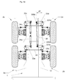
- the module wheel according to the invention is used to make two associated sets of wheels on the same chassis.
- a first wheel module (2a) is thus paired with a second wheel module (2b) to form a first set of wheels.
- a third module (2c) is paired with a fourth wheel module (2d) to form a second set of wheels.
- each wheel train the two modules are coupled in direction by a steering bar as described above.
- the command to each of the two trains is carried out by two cylinders (34a, 34c) as described above. Both trains can also be coupled in direction, by connecting with a drawbar (35), a steering arm of one train with a steering arm of the other train.
- the steering is obtained by a retraction of the jack (34a) controlling a module (2a) of one of the wheel sets, and by an extension of the jack (34c) controlling a module (3C) of the other wheel set.
- This action causes the arm (33a, 33c) for steering the corresponding modules.
- This pivoting of each controlled steering arm causes the arm to pivot simultaneously (33b, 33d) direction of the other module (2b, respectively 2d) of each train.
- the pivoting of the steering arm of each module then causes the steering of the wheel of each module.
- the steering drawbar (35) can for example be substantially in the chassis axis and connect the wheel modules located on the same side of the frame. This steering rod is then connected by a pivot link (335b, 335d), vertical axis, to the second part of the steering arm of each of these two wheel modules (2b, 2d).
- the two cylinders (34a, 34c) are then also in longitudinal position, fixed on a part of the frame (1) located between the two trains, and control the two modules (2a, 2c) located on the side opposite the steering drawbar (35).
- These two cylinders can then be connected by a pivot connection (334a, 334c), of vertical axis, to the second part of the arm direction of each of these two wheel modules (2a, 2c).
- Such coupling of two sets of wheels can allow for example ensure good coordination of their positions, or compensate for cylinder failures or inaccuracies.
- Such coupling between two trains can also strengthen the action of each cylinder by transmitting the force of the other cylinder, or allow the use of single acting cylinders or a single cylinder double-acting.
- This geometry is calculated for each train and provides values of lengths of steering rods (32) depending on the desired position for the turning center. These values are determined so that a direction control plane (d8) passing through both the axis (d2) of pivoting of the wheel knuckle (25) and through the center of the ball joint (322) controlling the pivoting forms a determined angle, called angle (a8), of steering control with the running surface of the wheel.
- the lengths of the steering rods of the modules (2c, 2d) of the second train and the geometry of the drawbar are determined for that the steering center of the second train is the same as the center of steering of the first train.
- This geometry is determined in particular by fixing the angle (a9) that forms with the axis (d0) of the chassis with a straight line (d9) passing through the center of the crankpins (335b, 335d) connecting the drawbar to the steering arm of a module (2b, 2d) of each of the two sets of wheels.
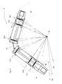
- a vehicle (5) comprises two half-vehicles (51, 52) opposite, articulated between them for example by a drawbar (53), and each provided with a cabin (510, 520) of conduct.
- Each of these half-vehicles (51, 52) comprises a chassis mounted on three sets of wheels (511, 512, 513 respectively 521, 522, 523) each comprising two wheel modules according to the invention.
- the vehicle can be driven from either of the two cabins, depending on needs and direction of travel. Driving can also be done from both cabins at the same time, for example in the case of complex or delicate maneuvers, each cabin then controlling the sets of wheels it includes.
- the six wheel sets are made up of wheel modules comprising a suspension function and a directing function. At least one of the six undercarriages have a driving function, preferably on both wheels.
- each of these trains (511, 512, 513, respectively 521, 522, 523) directors is carried out according to a sketch ensuring a steering where the axes of its wheels intersect in the same center turning.
- the two half-vehicles being articulated between them, their centers can be superimposed at the same point (c5).
- This the steering centers of the two cabins can be superimposed by electronic coordination of the steering of the steering trains of the two Half vehicles.
- One of the two cabins then orders its trains itself managers, for example by mechanical and hydraulic control, while the steering trains of the other cabin operate in a so-called self-steering mode.
- one (51) of the two half-vehicles comprises the energy systems, the other (52) using the systems carried by the first and does not comprising only two sets of wheels (521, 522).
- Each of the half vehicles (51, 52) comprises a load plate (541, 542) capable of receiving various prefabricated objects, devices, or elements, such as tunnel segments in concrete.
- an embodiment of a vehicle according to the invention can carry a load of the order of twice 20 tonnes, for a width of the order 2 m and a height of about 1.80 m.
- a vehicle (6) comprises two tractor half-vehicles (61, 62) of opposite pipes supporting the two ends of a structure (63) load-carrying unit, through articulated links pivoting around axes substantially vertical.
- Each of these half-vehicles (61, 62) comprises a control cabin (610, 620) and a chassis mounted on two trains (611, 612, respectively 621, 622) of wheels each comprising two wheel modules according to the invention.
- the vehicle can be driven from any of the two cabins, depending on needs and direction of travel.
- the driving can also be done from both cabins at the same time, each cabin then controlling the wheel sets which it comprises.
- the four wheel sets are made up of wheel modules comprising a suspension function. At least one of the four trains wheels has a driving function, preferably on its two wheels. All wheel sets have a guiding function.
- the trains (611, 612, respectively 621, 622) of wheels of each of the two cabs (61, respectively 62) are coupled together as described above to be able to turn in the same turning center (c61, respectively c62) for each of the cabins.
- Being able to steer trains from each cabin independently of each other thus allows the vehicle to follow a monotrace trajectory, located inside a width corridor (L61) little greater than the width of the vehicle itself. Due to the multiple joints of the vehicle, this trajectory can present changes of direction little spaced from the total length of the vehicle.
- the fact of steer the trains of the two cabins at the same time, in a rotation in opposite directions, also allows the vehicle to make a turn according to a particularly short turning radius.
- the turning trains from each of the two cabins can be controlled from the cabin which allows the operator to be in a good position to appreciate distances or avoid obstacles.
- the whole vehicle can be driven from a single cabin, called a cabin driving.
- the trains of one of the cabins, for example the leading cabin, are then ordered directly, while the trains in the other cabin operate in self-directing mode. That is to say that the deflection of these trains self-directing is calculated as and when to maintain their center steering on that of the trains of the steering half-vehicle, or in function other trajectory criteria, for example by servo means using sensors or encoders.
- the trains of each of the cabins are coupled to each other either by a drawbar as described higher, either by means of servo controlled in a way electronics or IT.
- the steering rods have a length adjustable by a device adjustable by the user. During a trip in crab, it is then possible to keep the wheels of the same train parallel between them, and therefore without any turning center.
- crab displacement position is just one example of the configurations and trajectories that a vehicle according to the invention.
- being able to turn each train of wheels independently of the others allows an infinity of trajectories without departing from the spirit of the invention.
- one (61) of the two half tractor units includes energy systems, the other (62) using systems carried by the former.
- Each of the half vehicles (61, 62) has a hinge which supports one end of a plate (64) of load capable of receiving various objects, devices, or prefabricated elements, such than a concrete mortar transport bucket.
- a realization of a vehicle according to the invention can carry a charge of the order of 25 tonnes, for a width of around 2 m and a height of around 1.80 m.
- a wheel module may include any combination of functions here described without departing from the spirit of the invention.
- a module can thus include for example a suspension function without directing function, as well only a directing function without a suspension function. Motor functions and braking can also be performed or not on any modules used for a machine or vehicle.
Abstract
Description
La présente invention concerne un module de roue utilisé pour la construction d'un engin ou véhicule spécial de chantier ou de manutention, ainsi qu'un tel engin ou véhicule.The present invention relates to a wheel module used for construction of a special site or handling machine or vehicle, as well as such a machine or vehicle.
Dans des chantiers importants ou spécifiques, par exemple de construction ou de transbordement de charges, certaines tâches sont assurées par des engins mobiles ou véhicules spéciaux conçus et construits spécifiquement en vue de ces tâches. De tels engins peuvent servir par exemple à transporter des charges lourdes ou encombrantes à l'intérieur du chantier, par exemple entre un poste de fabrication et leur emplacement définitif de mise en place ou simplement dans des docks ou une zone de transbordement.In large or specific projects, for example construction or transfer of loads, certain tasks are ensured by mobile devices or special vehicles designed and built specifically for these tasks. Such devices can be used by example of transporting heavy or bulky loads inside the site, for example between a manufacturing station and their location final placement or simply in docks or an area of transhipment.
Dans le cas de véhicules à roues, de tels engins sont souvent réalisés en très petites séries ou sur commande, et sont construits à partir d'un châssis supporté par un ou plusieurs trains de roues. Pour des raisons de capacité de charge et de simplicité de conception, et pour pouvoir utiliser des sous-ensembles préexistant sur le marché, un tel train de roues est habituellement conçu sous la forme d'un pont disposé sous un châssis et supportant une partie de ce châssis. On peut définir un tel pont comme un ensemble de plusieurs roues réparties des deux côtés du châssis, et portées par une structure elle-même mobile par rapport au châssis, par exemple comportant un essieu non suspendu passant sous le châssis. Cette structure peut comporter des éléments d'entraínement pour des roues motrices, et des éléments de directions pour des roues directrices. Ce pont est ainsi positionné sous le châssis, le plus souvent par l'intermédiaire d'éléments élastiques et d'éléments amortisseurs, de façon à réaliser une suspension évitant de transmettre au châssis toutes les irrégularités du sol lors du roulement.In the case of wheeled vehicles, such devices are often produced in very small series or on order, and are built from a chassis supported by one or more sets of wheels. For reasons of capacity load and simplicity of design, and to be able to use sub-assemblies pre-existing on the market, such a wheel set is usually designed as a bridge arranged under a frame and supporting a part of this chassis. We can define such a bridge as a set of several wheels distributed on both sides of the chassis, and carried by a structure itself movable relative to the chassis, for example comprising a unsprung axle passing under the chassis. This structure may include drive elements for drive wheels, and directions for steered wheels. This bridge is thus positioned under the chassis, most often by means of elastic elements and elements shock absorbers, so as to produce a suspension avoiding transmitting to the chassis all the irregularities of the ground during the rolling.
Dans certains types de chantiers se présentent des contraintes particulières en matière d'encombrement. En particulier lors de la construction de tunnels, qui est un cas de plus en plus fréquent, il est important que certains engins de travail, de transport, ou de manutention puissent emprunter des passages qui présentent des dimensions très limitées.In some types of construction sites there are constraints particular in terms of space. Particularly during construction of tunnels, which is an increasingly common case, it is important that some work, transport or handling equipment can borrow passages which have very limited dimensions.
De façon à améliorer le rendement ou les performances de tels véhicules, il faut alors pouvoir disposer d'un mode de liaison au sol permettant de transporter de lourdes charges tout en conservant des dimensions extérieures faibles. Il est donc utile de pouvoir positionner le châssis le plus bas possible pour pouvoir utiliser au maximum l'espace vertical disponible.In order to improve the yield or performance of such vehicles, it must then be possible to have a ground connection mode allowing transport heavy loads while maintaining dimensions weak exterior. It is therefore useful to be able to position the lowest chassis possible in order to make maximum use of the vertical space available.
Un des buts de l'invention est ainsi de proposer un dispositif de liaison au sol par roue permettant de réaliser un train de roues supportant un châssis positionné le plus bas possible.One of the aims of the invention is thus to propose a connection device on the ground by wheel making it possible to produce a set of wheels supporting a chassis positioned as low as possible.
Un autre but de l'invention est de proposer un véhicule utilisant un tel dispositif de roue.Another object of the invention is to propose a vehicle using such a wheel device.
Du fait d'un faible espace disponible sur le chantier, il est également utile pour un tel véhicule de pouvoir manoeuvrer selon des rayons de braquage très court ou même de pouvoir se déplacer « en crabe », c'est à dire selon une direction non longitudinale par rapport au véhicule.Due to the limited space available on site, it is also useful for such a vehicle to be able to maneuver according to turning radii very short or even being able to move "in crab", that is to say according to a non-longitudinal direction relative to the vehicle.
Un des buts de l'invention est ainsi de proposer un véhicule dont plusieurs trains de roues sont directeurs, en parallèle ou en opposition entre eux.One of the aims of the invention is thus to propose a vehicle whose several sets of wheels are steering, in parallel or in opposition between them.
Ce but est atteint par un module de liaison au sol supportant tout ou partie d'un châssis de véhicule ou engin spécial de chantier ou de manutention, ce module comprenant une ou plusieurs roues permettant le déplacement de tout ou partie de ce véhicule, caractérisé en ce qu'au moins une de ces roues supporte une part du châssis par des moyens de liaison au sol commandés, disposés sur au moins un côté du châssis, occupant un volume qui ne s'étend pas jusqu'à la partie médiane du châssis selon l'axe de la roue, et comportant la possibilité d'un déplacement de l'axe de la roue par rapport au châssis assurant ainsi une fonction de suspension, indépendamment de la position ou de l'état des roues ou moyens de liaison au sol supportant ledit châssis et situés à l'extérieur de ce module et indépendamment du déplacement de l'axe des roues des autres modules par rapport au châssis.This goal is achieved by a ground connection module supporting all or part of a vehicle chassis or special construction or handling equipment, this module comprising one or more wheels allowing the movement of all or part of this vehicle, characterized in that at least one of these wheels supports part of the chassis by controlled ground connection means, arranged on at least one side of the chassis, occupying a volume which does not extend not to the middle part of the chassis along the axis of the wheel, and comprising the possibility of a displacement of the axis of the wheel relative to the chassis thus ensuring a suspension function, regardless of the position or the condition of the wheels or ground connection means supporting said chassis and located outside of this module and independently of the axis movement wheels of the other modules in relation to the chassis.
Selon une particularité, la roue est montée par une liaison pivot sur une fusée, dite fusée de roue, cette fusée de roue étant mobile en rotation par rapport au châssis selon un axe de direction formant avec la surface où s'appuie la roue un angle supérieur à 45°, la rotation de la fusée de roue autour de cet axe de direction étant commandée par déplacement d'un élément, dit biellette de direction, relié à la fusée de roue en un point décalé d'une certaine distance par rapport à l'axe de direction, cette rotation permettant au module d'assurer une fonction directrice.According to one feature, the wheel is mounted by a pivot link on a rocket, called wheel rocket, this wheel rocket being movable in rotation by relation to the chassis along a direction axis forming with the surface where the wheel leans an angle greater than 45 °, the rotation of the wheel spindle around of this steering axis being controlled by displacement of an element, called steering rod, connected to the wheel stub at a point offset by a certain distance from the steering axis, this rotation allowing the module to provide a guiding function.
Selon une particularité, la fusée de roue est reliée au châssis par l'intermédiaire d'une structure déformable, dite structure de suspension, apte à se déformer dans une direction verticale, ou perpendiculaire à la face du châssis portant le module, cette déformation se faisant selon la cinématique d'un parallélogramme de côtés rigides et de sommets d'angles variables, la biellette de direction étant reliée à ses deux extrémités par des liaisons rotules lui permettant de rester sensiblement parallèle à l'un des côtés du parallélogramme.According to one feature, the wheel spindle is connected to the chassis by through a deformable structure, called suspension structure, suitable for deform in a vertical direction, or perpendicular to the face of the chassis carrying the module, this deformation taking place according to the kinematics of a parallelogram of rigid sides and vertices of variable angles, the steering rod being connected at its two ends by ball joints allowing it to remain substantially parallel to one of the sides of the parallelogram.
Selon une particularité, la déformation de la structure déformable est commandée par la variation de longueur d'une jambe de suspension reliée à ses deux extrémités à deux éléments formant des côtés opposés du parallélogramme de déformation de cette structure déformable, cette jambe de suspension réalisant un contrôle de la hauteur de la suspension sous l'action éventuellement partielle d'un circuit de fluide sous pression.According to one feature, the deformation of the deformable structure is controlled by the variation in length of a suspension strut connected to its two ends with two elements forming opposite sides of the deformation parallelogram of this deformable structure, this leg of suspension carrying out a control of the height of the suspension under the action possibly partial of a pressurized fluid circuit.
Selon une particularité, la jambe de suspension réalise une fonction d'amortissement, de maintien de la hauteur, ou de réglage de la hauteur, ou une combinaison de ces fonctions.According to one feature, the suspension strut performs a function cushioning, maintaining the height, or adjusting the height, or a combination of these functions.
Selon une particularité, le module comprend un moteur entraínant en rotation la roue par rapport à la fusée de roue autour de l'axe de roue.According to one feature, the module comprises a motor driving in rotation of the wheel with respect to the wheel spindle around the wheel axle.
Selon une particularité, le moteur fonctionne sous l'action d'un fluide sous pression ou d'un courant électrique. According to a particular feature, the engine operates under the action of a fluid under pressure or electric current.
Du fait d'un faible espace disponible sur le chantier, il est également utile pour un tel véhicule de pouvoir manoeuvrer selon des rayons de braquage très court ou même de pouvoir se déplacer « en crabe », c'est à dire selon une direction non longitudinale par rapport au véhicule.Due to the limited space available on site, it is also useful for such a vehicle to be able to maneuver according to turning radii very short or even to be able to move "in crab", ie according to a non-longitudinal direction relative to the vehicle.
Un des buts de l'invention est ainsi de proposer un véhicule dont plusieurs trains de roues sont directeurs, en parallèle ou en opposition entre eux.One of the aims of the invention is thus to propose a vehicle whose several sets of wheels are steering, in parallel or in opposition between them.
Ce but est atteint par un véhicule en une ou plusieurs parties et comportant au moins un train de roues directrices composé d'au moins deux modules selon l'une des revendications précédentes, ces deux modules étant disposés de chaque côté du châssis et incluant une fonction directrice, caractérisé en ce que, dans au moins un des modules, le plan de roulement de la roue forme un angle, dit angle de commande de direction avec un plan de commande de direction, ce plan passant par l'axe de direction et le centre de rotation de la liaison rotule reliant la fusée de roue et la biellette de direction, cet angle de commande de direction étant choisi pour que, lors du braquage d'un train, les axes des roues des modules d'un même train définissent un point déterminé, dit centre de braquage, par l'intersection de leur projection verticale sur le sol.This goal is achieved by a vehicle in one or more parts and comprising at least one set of steered wheels composed of at least two modules according to one of the preceding claims, these two modules being arranged on each side of the chassis and including a directing function, characterized in that, in at least one of the modules, the running surface of the wheel forms an angle, called the steering control angle with a plane of steering control, this plane passing through the steering axis and the center of rotation of the ball joint connecting the wheel stub and the steering rod, this steering control angle being chosen so that, when turning of a train, the axes of the wheels of the modules of the same train define a determined point, called turning center, by the intersection of their projection vertical on the ground.
Selon une particularité, au moins un module d'un train comporte une biellette de direction reliée du côté du châssis à une extrémité d'un bras de direction, ce bras de direction étant relié au châssis par une liaison pivot et étant commandé en rotation par un actionneur, le train comportant au moins une barre de direction reliant le bras de direction ou la biellette de direction d'un module avec le bras de direction ou la biellette de direction d'un autre module du même train.According to one feature, at least one module of a train comprises a steering rod connected to the chassis side at one end of an arm steering, this steering arm being connected to the chassis by a pivot link and being controlled in rotation by an actuator, the train comprising at least a steering rod connecting the steering arm or the steering rod of a module with the steering arm or steering rod of another module on the same train.
Selon une particularité, au moins un bras de direction présente une forme en « L », l'intersection des branches supportant la liaison au châssis, l'une des branches étant reliée à la biellette de direction et à la barre de direction, l'autre branche étant reliée à l'actionneur cet actionneur comprenant un vérin formant avec l'axe longitudinal du châssis un angle inférieur à 45°. According to one feature, at least one steering arm has a "L" shape, the intersection of the branches supporting the connection to the chassis, one of the branches being connected to the steering rod and to the steering, the other branch being connected to the actuator, this actuator comprising a cylinder forming with the longitudinal axis of the chassis an angle less than 45 °.
Selon une particularité, le véhicule comporte plusieurs modules de roues directrices, au moins un de ces modules, dit autodirecteur, étant commandé en direction par un actionneur associé à des moyens de calcul et de commande aptes à coordonner le braquage de ce train en fonction de celui des autres trains du véhicule.According to a particular feature, the vehicle comprises several modules of steered wheels, at least one of these modules, called seeker, being controlled in direction by an actuator associated with calculation means and control capable of coordinating the deflection of this train according to that other trains in the vehicle.
Selon une particularité, le véhicule comporte au moins un train autodirecteur dont le braquage est déterminé par les moyens de calcul et de commande de façon à ce que son centre de braquage soit sensiblement superposé à celui d'au moins un autre train de roues directrices du véhicule.According to one feature, the vehicle comprises at least one train seeker whose steering is determined by the means of calculation and controls so that its turning center is substantially superimposed on that of at least one other set of steered wheels of the vehicle.
Selon une particularité, le véhicule comporte en une de ses extrémités au moins deux trains de roues directrices, une extrémité du bras de direction d'un module étant reliée avec une extrémité du bras de direction d'un module d'un autre train par un timon de direction, cette liaison assurant une coordination du braquage des deux trains.According to one feature, the vehicle has at one of its ends at least two sets of steered wheels, one end of the steering arm of a module being connected with one end of the steering arm of a module another train by a drawbar, this link ensuring a coordination of the steering of the two trains.
Selon une particularité, le timon de direction est relié aux bras de direction d'un module de chaque train en deux points définissant une droite formant un angle déterminé avec un plan incluant les axes des liaisons pivots reliant ces deux bras de direction au châssis, la valeur de cet angle pouvant être choisie pour que les centres de braquage des deux trains soient sensiblement superposés.According to one particularity, the steering drawbar is connected to the arms of direction of a module of each train at two points defining a straight line forming a determined angle with a plane including the axes of the pivot connections connecting these two steering arms to the chassis, the value of this angle possibly be chosen so that the turning centers of the two trains are substantially superimposed.
Selon une particularité, le bras de direction d'au moins un module de chaque train est commandé par un actionneur.According to one feature, the steering arm of at least one module each train is controlled by an actuator.
Selon une particularité, le véhicule présente une forme allongée et comporte au moins deux trains de roues directrices situés de chaque côté du centre de gravité du véhicule, le braquage de ces trains étant commandé et coordonné par des moyens de commande de façon à ce que les directions imprimées au châssis par ces deux trains soient dirigées de deux côtés opposés du châssis, cette coordination de braquage de ces trains permettant ainsi un braquage du véhicule selon un faible rayon de braquage.According to one feature, the vehicle has an elongated shape and has at least two sets of steered wheels located on each side of the center of gravity of the vehicle, the steering of these trains being controlled and coordinated by control means so that the directions printed on the chassis by these two trains are directed from two sides opposite of the chassis, this steering coordination of these trains allowing thus a turning of the vehicle according to a small turning radius.
Selon une particularité, le véhicule présente une forme allongée et comporte au moins deux trains de roues directrices situés de chaque côté du centre de gravité du véhicule, le braquage de ces trains étant commandé et coordonné par des moyens de commande de façon à ce que les directions imprimées au châssis par ces deux trains soient dirigées du même côté du châssis, cette coordination de braquage de ces trains permettant ainsi un déplacement de l'ensemble du véhicule « en crabe », c'est à dire dans une direction incluant une composante latérale par rapport au véhicule.According to one feature, the vehicle has an elongated shape and has at least two sets of steered wheels located on each side of the center of gravity of the vehicle, the steering of these trains being controlled and coordinated by control means so that the directions printed on the chassis by these two trains are directed on the same side of the chassis, this steering coordination of these trains thus allowing a movement of the whole vehicle "in crab", that is to say in a steering including a lateral component with respect to the vehicle.
Selon une particularité, le véhicule comporte au moins deux cabines ou postes de commandes, chacune de ces cabines comportant des moyens de commande de l'ensemble des modules de roues du véhicule.According to a particular feature, the vehicle comprises at least two cabins or control stations, each of these cabins comprising means of control of all vehicle wheel modules.
Selon une particularité, le véhicule comporte au moins deux cabines ou postes de commandes, chacune de ces cabines étant apte à commander séparément une partie des modules ou trains de roues du véhicule.According to a particular feature, the vehicle comprises at least two cabins or control stations, each of these cabins being able to control separately a part of the vehicle modules or wheel sets.
Selon une particularité, le véhicule comporte deux demi-véhicules dos à dos, articulés entre eux directement ou par l'intermédiaire d'un timon, chaque demi-véhicule comportant un plateau de charge, dont la surface de charge est située au-dessous de l'axe des roues, et une cabine de commande et étant supportée par au moins un train de roues directrices du côté de sa cabine et par au moins un train de roues non directrices du côté de l'articulation.According to one feature, the vehicle comprises two back half-vehicles backpack, hinged together directly or by means of a drawbar, each half-vehicle with a load plate, the load surface of which is located below the wheel center line, and a control cabin and being supported by at least one set of steered wheels on the side of its cabin and by at least one set of non-steerable wheels on the side of the joint.
Selon une particularité, le véhicule comporte deux demi-véhicules tracteur dos à dos et supportant chacun une extrémité d'une partie de charge par une articulation, chaque demi-véhicule comportant une partie de plateau de charge, dont la surface de charge est située au-dessous de l'axe des roues, et une cabine de commande et étant supporté par au moins un train de roues directrices et au moins un train de roues non directrices.According to one feature, the vehicle comprises two half-vehicles tractor back to back and each supporting one end of a load part by an articulation, each half-vehicle comprising a plate portion of load, the load surface of which is located below the wheel center line, and a control cabin and being supported by at least one set of wheels steerable and at least one set of non-steerable wheels.
L'invention, avec ses caractéristiques et avantages, ressortira plus clairement à la lecture de la description faite en référence aux dessins annexés dans lesquels :
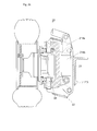
- la figure 1 représente une vue en coupe transversale d'un véhicule comportant un train de roues réalisé à partir de deux modules selon l'invention, dans une variante comportant suspension, direction et motricité ;
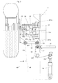
- les figures 2a et 2b représentent des vues partielles en coupe transversale selon l'axe de pivotement de direction, d'un module de roue selon l'invention dans deux positions différentes de suspension, dans une variante comportant suspension, direction et motricité (tringlerie de direction non représentée) ;
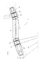
- la figure 3 représente une vue de dessus d'un module selon l'invention, incluant une demi-coupe au niveau de l'axe inférieur de la jambe de suspension, dans une variante comportant suspension, direction et motricité ;
- les figures 4a et 4b représentent une vue de dessus d'une partie de châssis utilisant deux trains de roues constitués de modules selon l'invention, le châssis étant figuré comme transparent, dans deux positions différentes de la direction, dans une variante comportant suspension, direction et motricité ;
- la figure 5 représente une vue schématique de dessus d'un véhicule selon l'invention en position de braquage, dans une configuration à deux demi-véhicules comportant chacun une cabine et trois trains directionnels ;
- les figures 6a et 6b représentent une vue schématique de dessus d'un véhicule selon l'invention, en position de virages sinueux et respectivement en position de déplacement latéral oblique ou « en crabe », dans une configuration à deux cabines pivotantes autour d'une partie porte-charge centrale, et comportant quatre trains directionnels ;
- la figure 7 représente une vue latérale en transparence d'un véhicule selon l'invention dans une configuration à deux cabines conduisant chacune une partie porte-charge, ces deux parties porte-charge étant reliées entre elles de façon articulée ;
- la figure 8 représente une vue latérale en transparence d'un véhicule selon l'invention dans une configuration à deux cabines pivotantes autour d'une partie porte-charge centrale.
- FIG. 1 represents a cross-sectional view of a vehicle comprising a train of wheels produced from two modules according to the invention, in a variant comprising suspension, steering and traction;
- Figures 2a and 2b show partial cross-sectional views along the steering pivot axis, of a wheel module according to the invention in two different suspension positions, in a variant comprising suspension, steering and traction (linkage of management not shown);
- FIG. 3 represents a top view of a module according to the invention, including a half-section at the level of the lower axis of the suspension strut, in a variant comprising suspension, direction and traction;
- FIGS. 4a and 4b represent a top view of a part of the chassis using two sets of wheels made up of modules according to the invention, the chassis being shown as transparent, in two different positions of the steering, in a variant comprising suspension, direction and motor skills;
- FIG. 5 represents a schematic top view of a vehicle according to the invention in the steering position, in a configuration with two half-vehicles each comprising a cabin and three directional trains;
- FIGS. 6a and 6b represent a schematic view from above of a vehicle according to the invention, in the position of sinuous turns and respectively in the oblique or “crab” lateral displacement position, in a configuration with two cabins pivoting around a central load-bearing part, and comprising four directional trains;
- FIG. 7 represents a transparent side view of a vehicle according to the invention in a configuration with two cabins each driving a load-carrying part, these two load-carrying parts being connected to each other in an articulated manner;
- FIG. 8 represents a transparent side view of a vehicle according to the invention in a configuration with two pivoting cabins around a central load-carrying part.
Dans l'architecture d'un véhicule ou engin spécial comportant un châssis reposant sur au moins deux roues, on définira comme un train de roues un groupe d'au moins deux roues disposées de chaque côté du châssis, en particulier partageant sensiblement le même axe lorsque le véhicule progresse selon son axe principal.In the architecture of a special vehicle or machine comprising a chassis resting on at least two wheels, we will define as a train of wheels a group of at least two wheels arranged on each side of the chassis, in particular sharing substantially the same axis when the vehicle progresses along its main axis.
Dans la présente description, les modules de roues sont présentés comme utilisés par paires pour constituer des trains de roues. Sans sortir de l'esprit de l'invention, il est bien sûr tout à fait possible d'utiliser également de tels modules en nombres impairs. De la même façon, il est également possible d'utiliser de tels modules sans qu'ils soient appairés en trains de roues, par exemple disposés en quinconce des deux côtés du véhicule. Il est également possible de disposer plusieurs roues couplées dans un même module, par exemple pour augmenter les capacités de charge ou améliorer la maintenance ou la sécurité. Il est également possible d'utiliser de tels modules de roues pour supporter un châssis ou une partie de châssis présentant une forme différente du châssis classique de forme allongée. Des engins spéciaux articulés en plusieurs parties, ou au châssis de formes diverses, par exemple carré, peuvent ainsi utiliser de tels modules de roues sans sortir de l'esprit de l'invention.In the present description, the wheel modules are presented as used in pairs to form wheel sets. Without leaving the spirit of the invention, it is of course entirely possible to also use such modules in odd numbers. In the same way, it is also possible to use such modules without being paired in wheel sets, for example example staggered on both sides of the vehicle. he is also it is possible to have several wheels coupled in the same module, by example to increase load capacities or improve maintenance or security. It is also possible to use such wheel modules for supporting a frame or part of a frame having a different shape of the classic elongated chassis. Special vehicles articulated in several parts, or chassis of various shapes, for example square, can thus use such wheel modules without departing from the spirit of the invention.
De façon à laisser disponible l'espace compris entre les roues opposées d'un train de roues, un véhicule selon l'invention repose sur des modules de roues fixés directement à son châssis, par exemple sur le côté du châssis. Une telle disposition permet de faire descendre le châssis très bas, par exemple jusqu'à la limite de la garde au sol du véhicule ou à la hauteur de l'axe des roues, sans avoir à laisser sous le châssis l'espace nécessaire au débattement d'un essieu non suspendu. So as to leave available the space between the wheels opposite of a set of wheels, a vehicle according to the invention rests on wheel modules fixed directly to its chassis, for example on the side of the frame. Such an arrangement allows the chassis to be lowered very low, by example up to the limit of the ground clearance of the vehicle or at the height of the axis wheels, without having to leave space under the chassis for the travel of an unsprung axle.
Dans le mode de réalisation illustré en figure 1, le véhicule selon l'invention comporte ainsi un châssis (1) comprenant par exemple un caisson ou deux poutres (11, 12) longitudinales à profil en « I ». De chaque côté de ce châssis, les modules (2) de roue sont ainsi fixés sur le châssis et occupent un espace (20) qui ne s'étend pas jusqu'à la partie (10) médiane de ce châssis. Lorsque des modules sont disposés de façon opposée de chaque côté du châssis, cette partie médiane s'entend bien sûr comme située au milieu de la distance séparant ces deux roues ou modules de roue et descendant jusqu'à une hauteur au moins inférieure à celle de l'axe des roues. Pour des modules de roue qui ne sont pas appairés, voire ne sont disposés que d'un seul côté du châssis, cette partie médiane peut alors naturellement s'interpréter pour chaque module comme étant une partie du véhicule soutenue entre autres par ce module, cette partie incluant l'axe de la roue du module.In the embodiment illustrated in FIG. 1, the vehicle according to the invention thus comprises a chassis (1) comprising for example a box or two longitudinal beams (11, 12) with an “I” profile. On either side of this chassis, the wheel modules (2) are thus fixed on the chassis and occupy a space (20) which does not extend to the middle part (10) of this chassis. When modules are arranged opposite each side of the chassis, this middle part is of course understood to be located in the middle of the distance between these two wheels or wheel modules and down to a height at least less than that of the wheel center line. For modules wheels that are not paired, or are only arranged on one side of the chassis, this middle part can then naturally be interpreted to each module as being a part of the vehicle supported inter alia by this module, this part including the axis of the module wheel.
Il doit être bien compris que la libération de l'espace (20), par l'utilisation d'un module selon l'invention, n'est pas empêchée par la présence de divers conduits ou organes mécaniques ou autres dispositif pouvant courir sous le châssis ou relier entre eux les modules de roue. Des barres, vérins, ou tringleries de direction peuvent en particulier être placés sous le châssis sans faire perdre le gain d'espace obtenu par l'utilisation d'un module de roue selon l'invention.It should be understood that the liberation of space (20), by the use of a module according to the invention is not prevented by the presence various ducts or mechanical parts or other devices capable of running under the chassis or connect the wheel modules together. Bars, cylinders, or steering linkages can in particular be placed under the chassis without lose the space gain obtained by using a wheel module according to the invention.
Dans ce mode de réalisation, chaque module présente une fonction de suspension, une fonction directrice, une fonction de freinage, et une fonction motrice. Un tel module est illustré en figures 1, 2a, 2b et 3, et comprend une roue, par exemple sous la forme d'un pneumatique (28) monté de façon connue sur une jante (27). Cette jante est mobile en rotation autour d'un axe (d1) de roue, et est fixée par des moyens connus sur une fusée (25) de roue, par exemple par un montage de roulements radiaux avec butées axiales. La rotation de la roue peut être freinée ou bloquée par des moyens de freinage, comme un frein (26) à tambour.In this embodiment, each module has a function of suspension, a steering function, a braking function, and a function driving. Such a module is illustrated in Figures 1, 2a, 2b and 3, and includes a wheel, for example in the form of a tire (28) mounted so known on a rim (27). This rim is movable in rotation about an axis (d1) wheel, and is fixed by known means on a wheel spindle (25), for example by mounting radial bearings with axial stops. The rotation of the wheel can be braked or blocked by braking means, as a drum brake (26).
Dans ce mode de réalisation, une fonction motrice est assurée par un moteur hydraulique (29) d'un type connu, monté sur la fusée (25) de roue et entraínant la jante en rotation. Ce moteur hydraulique est alimenté en fluide sous pression à travers des conduites souples (non représentés) en provenance d'un circuit hydraulique mis sous pression par des moyens connus. D'autres types de moteurs ou motoréducteurs peuvent être utilisés, comme des moteurs pneumatiques ou électriques montés directement à l'intérieur de chaque module de roue. En effet, de tels moteurs hydrauliques, pneumatiques ou électriques sont particulièrement avantageux du fait de leur faible encombrement. De même, ils sont faciles à commander à distance et leur raccordement en énergie peut facilement se faire de façon souple, par des conduites souples ou câbles électriques. Ces aspects simplifient grandement leur intégration à l'intérieur d'un tel module par rapport à une transmission mécanique depuis un moteur centralisé.In this embodiment, a motor function is provided by a hydraulic motor (29) of a known type, mounted on the wheel spindle (25) and driving the rim in rotation. This hydraulic motor is supplied with fluid under pressure through flexible pipes (not shown) in from a hydraulic circuit pressurized by known means. Other types of motors or geared motors can be used, such as pneumatic or electric motors mounted directly inside each wheel module. Indeed, such hydraulic, pneumatic motors or electric are particularly advantageous because of their low footprint. Likewise, they are easy to control remotely and their energy connection can easily be done flexibly, by flexible pipes or electrical cables. These aspects greatly simplify their integration inside such a module with respect to a transmission mechanical from a centralized motor.
Une fonction directrice est assurée par une rotation de la fusée (25) de roue par rapport à une fusée (24) fixe, autour d'un axe (d2) de direction sensiblement vertical. Cette rotation est guidée par pivotement de la fusée (25) de roue autour de deux paliers lisses comprenant une pièce (241, 242) de pivot et des coussinets (241a, 242a) cylindriques antifrictionnels. Lors de cette rotation, la fusée de roue supporte la fusée fixe, par exemple par l'intermédiaire d'un coussinet (242b) antifrictionnel en un disque annulaire horizontal centré sur ce même axe (d2).A guiding function is ensured by a rotation of the rocket (25) of wheel relative to a fixed rocket (24), around a steering axis (d2) substantially vertical. This rotation is guided by pivoting of the rocket (25) wheel around two plain bearings comprising a pivot part (241, 242) and anti-friction cylindrical bearings (241a, 242a). During this rotation, the wheel spindle supports the fixed spindle, for example via an anti-friction pad (242b) into a centered horizontal annular disc on this same axis (d2).
Cette rotation permettant la fonction directrice est commandée par un effort exercé sur une partie (251) de la fusée (25) de roue n'incluant pas l'axe (d2) de direction. Cet effort est appliqué par une biellette (32) de direction par l'intermédiaire d'une rotule (322) de fusée de type connu, apte à transmettre des efforts passant par un point constituant son centre de rotation tout en laissant libres toutes les rotations. Du côté opposé à la roue, la biellette (32) de direction est reliée à une première partie d'un bras (33) de direction par une rotule similaire, dite rotule (321) de bras. La première partie de ce bras (33) de direction est sensiblement parallèle au plan de rotation de la roue, et est reliée au châssis (1) par une liaison pivot autour d'un maneton (331) d'axe sensiblement vertical. En commandant la position angulaire de ce bras de direction autour de son axe (331) de rotation, on commande donc la position angulaire de la fusée (25) de roue autour de son axe (d2) de direction. This rotation allowing the directing function is controlled by a force exerted on a part (251) of the wheel stub (25) not including the axle (d2) direction. This effort is applied by a steering link (32) by through a rocket ball joint (322) of known type, capable of transmitting forces passing through a point constituting its center of rotation while leaving free all rotations. On the side opposite the wheel, the link (32) of steering is connected to a first part of a steering arm (33) by a similar ball joint, called arm ball joint (321). The first part of this arm (33) of steering is substantially parallel to the plane of rotation of the wheel, and is connected to the chassis (1) by a pivot link around a pin (331) with an axis substantially vertical. By controlling the angular position of this arm direction around its axis (331) of rotation, we therefore control the position angle of the wheel rocket (25) around its steering axis (d2).
Pour commander la position angulaire de ce module (2) de roue, le bras (33) de direction peut être relié à un actionneur d'un type connu, comme un vérin (34), fixé au châssis (1). Le bras (33) de direction peut comporter une deuxième partie sensiblement orthogonale à sa première partie. Le vérin (34) peut alors être positionné sensiblement selon l'axe du châssis (1), et agir sur le bras de direction à travers sa deuxième partie par une liaison pivot d'axe sensiblement vertical, par exemple un maneton (334).To control the angular position of this wheel module (2), the steering arm (33) can be connected to an actuator of a known type, such as a jack (34), fixed to the frame (1). The steering arm (33) may include a second part substantially orthogonal to its first part. The jack (34) can then be positioned substantially along the axis of the chassis (1), and act on the steering arm through its second part by a pivot pin connection substantially vertical, for example a crankpin (334).
Pour coupler la position angulaire de ce bras (33) de direction avec celle d'un autre module de roue, une barre (31) de direction peut être reliée par une liaison pivot ou rotule (311) à ce même bras de direction, par exemple entre son axe (331) de rotation et le point (321) de fixation de la biellette (32) de direction. Si la barre de direction est reliée de la même façon avec le bras de direction d'un autre module de roue similaire, les fonctions directrices de ces deux modules de roues fonctionneront alors de façon coordonnée.To couple the angular position of this steering arm (33) with that of another wheel module, a steering rod (31) can be connected by a pivot or ball joint (311) to this same steering arm, for example between its axis (331) of rotation and the point (321) of attachment of the rod (32) of management. If the steering rod is connected in the same way with the arm steering of another similar wheel module, the steering functions of these two wheel modules will then operate in a coordinated fashion.
Dans ce mode de réalisation, une fonction de suspension est réalisée par un ensemble d'éléments dont une section verticale forme un parallélogramme déformable. Ce parallélogramme comprend deux côtés sensiblement verticaux et parallèles entre eux, comprenant d'un côté la fusée (24) fixe et de l'autre côté une chape (21) fixée au châssis. Les deux autres côtés de ce parallélogramme sont constitués par deux bras (22, 23) de suspension sensiblement parallèles entre eux, l'un en bas et l'autre en haut, et dont la position angulaire varie avec le mouvement de la suspension. Ces bras de suspension sont articulés à ces deux premiers côtés, par des liaisons pivots selon des axes sensiblement horizontaux et parallèles entre eux. Le bras (22) inférieur de suspension est ainsi articulé à une de ses extrémités sur le bas de la chape (21) et à son autre extrémité sur le bas de la fusée (24) fixe, par exemple par pivotement autour de deux alignements de deux manetons (221a, 221b, respectivement 222a, 222b). De la même façon, le bras (23) supérieur de suspension est articulé à une de ses extrémités sur le haut de la chape (21) et à son autre extrémité sur le haut de la fusée (24) fixe, par exemple par pivotement autour de deux alignements de deux manetons (231 a, 231b, respectivement 232a, 232b). Chaque bras (22, 23) de suspension comprend lui-même deux barres parallèles solidarisées entre elles par une partie (229, 239) horizontale. A chacune de leurs extrémités, ces barres présentent un perçage qui reçoit le maneton participant à la liaison pivot. Dans la position supérieure de la suspension, cette partie horizontale reliant les deux barres du bras supérieur peut venir en contact avec une partie (219) saillante solidaire de la chape (1), réalisant ainsi une butée haute comportant des moyens élastiques et/ou d'amortissement.In this embodiment, a suspension function is performed by a set of elements of which a vertical section forms a deformable parallelogram. This parallelogram has two sides substantially vertical and parallel to each other, comprising on one side the rocket (24) fixed and on the other side a yoke (21) fixed to the chassis. Both other sides of this parallelogram consist of two arms (22, 23) of suspension substantially parallel to each other, one at the bottom and the other at the top, and whose angular position varies with the movement of the suspension. These arms of suspension are articulated on these first two sides, by pivot links along axes substantially horizontal and parallel to each other. The arm (22) lower suspension is thus articulated at one of its ends on the bottom of the yoke (21) and at its other end on the bottom of the fixed rocket (24), by example by pivoting around two alignments of two crankpins (221a, 221b, respectively 222a, 222b). Similarly, the upper arm (23) of suspension is articulated at one of its ends on the top of the yoke (21) and at its other end on the top of the fixed rocket (24), for example by pivoting around two alignments of two crankpins (231 a, 231b, respectively 232a, 232b). Each suspension arm (22, 23) comprises itself two parallel bars joined together by a part (229, 239) horizontal. At each of their ends, these bars have a hole which receives the pin participating in the pivot link. In the position upper part of the suspension, this horizontal part connecting the two bars of the upper arm can come into contact with a projecting part (219) integral with the yoke (1), thus producing a high stop comprising elastic means and / or depreciation.
Le mouvement de la suspension, c'est à dire la déformation verticale de ce parallélogramme, est contrôlé par la variation de longueur d'un élément télescopique, dit jambe (214) de suspension. Pour cela, cette jambe de suspension est fixée à son extrémité basse à la fusée (24) fixe et à son extrémité haute à la chape (21). Cette fixation se fait par des liaisons pivots d'axes sensiblement horizontaux, par exemple par des manetons munis de coussinets anti-frictionnels.The movement of the suspension, i.e. the vertical deformation of this parallelogram, is controlled by the variation in length of an element telescopic, said suspension leg (214). For this, this leg of suspension is fixed at its lower end to the fixed rocket (24) and to its high end to the yoke (21). This fixing is done by pivot connections substantially horizontal axes, for example by crank pins provided with anti-friction pads.
Ainsi qu'on le voit en passant de la figure 2a à la figure 2b, le soulèvement de la roue est autorisé par un pivotement des deux bras (22, 23), ce qui va avec un raccourcissement de la jambe de suspension. Ce raccourcissement se fait alors par pénétration d'une partie (214a) supérieure de la jambe dans une partie (214b) inférieure de cette même jambe.As seen from Figure 2a to Figure 2b, the lifting of the wheel is authorized by a pivoting of the two arms (22, 23), which goes with a shortening of the suspension leg. This shortening is then done by penetration of an upper part (214a) of the leg in a lower part (214b) of this same leg.
La jambe de suspension comprend un ou plusieurs actionneurs, par exemple des vérins hydrauliques, dont l'action permet de contrôler la déformation de la suspension. Ce contrôle peut correspondre à plusieurs effets. Un effet peut être de transmettre une partie de la charge du châssis à la roue, en limitant la déformation de la suspension. Un autre effet peut être d'amortir les oscillations du châssis par rapport à la roue en amortissant la déformation de la suspension. Un autre effet peut être de modifier ou d'ajuster la hauteur du châssis par rapport à la roue, en réglant la longueur de la jambe (214) de suspension. Ce contrôle de la suspension peut être avantageusement réalisé par l'action d'un fluide sous pression. Il est en effet courant de disposer d'un groupe de pression hydraulique sur les engins de chantiers ou de manutention, ce groupe étant utilisé pour manoeuvrer divers appendices de manutention ou pour contrôler certaines fonctions de l'engin. The suspension strut comprises one or more actuators, for example example of hydraulic cylinders, the action of which controls the deformation of the suspension. This control can correspond to several effects. An effect can be to transmit part of the load from the chassis to the wheel, by limiting the deformation of the suspension. Another effect may be to cushion the oscillations of the chassis relative to the wheel by damping the deformation suspension. Another effect can be to modify or adjust the height of the chassis relative to the wheel, adjusting the length of the leg (214) by suspension. This suspension control can advantageously be carried out by the action of a pressurized fluid. It is indeed common to have a hydraulic pressure group on construction or handling equipment, this group being used to maneuver various handling appendages or to control certain functions of the machine.
Dans une variante ou la jambe (214) de suspension est indépendante du reste du véhicule, cette jambe comprend des moyens élastiques (non représentés) d'un type connu lui permettant ainsi de transmettre à la fusée (24) fixe la charge de la chape (21), et donc une part de la charge du châssis (1). Selon les applications, cette jambe (214) de suspension peut également comporter des moyens d'amortissement, par exemple un amortisseur hydraulique ou à gaz, lui permettant d'amortir les variations de position de la suspension et de diminuer les oscillations du véhicule.In a variant where the suspension leg (214) is independent of the rest of the vehicle, this leg comprises elastic means (not shown) of a known type thus enabling it to transmit to the rocket (24) fixes the load of the yoke (21), and therefore part of the load of the frame (1). Depending on the applications, this suspension leg (214) can also include damping means, for example a shock absorber hydraulic or gas, allowing it to absorb variations in the position of the suspension and decrease the vehicle's oscillations.
Dans les modes de réalisation qui conjuguent une fonction directrice et une fonction de suspension, la biellette (32) de direction peut suivre sans détérioration les déformations de la suspension par pivotement de ses rotules (321, 322) suivant des axes horizontaux. Pour éviter de trop fortes contraintes de traction ou compression sur cette biellette, ou leur influence sur la commande de direction, les points de pivotements de ces mêmes rotules sont disposés à proximité des axes de pivotement des articulations de l'un des bras de suspension, par exemple les articulations (221, 222) du bras (22) inférieur de suspension.In the embodiments which combine a guiding function and a suspension function, the steering rod (32) can follow without deterioration of the deformation of the suspension by pivoting of its ball joints (321, 322) along horizontal axes. To avoid excessive constraints of traction or compression on this rod, or their influence on the steering control, the pivot points of these same ball joints are arranged near the pivot axes of the articulations of one of the arms suspension, for example the joints (221, 222) of the lower arm (22) suspension.
Dans un mode de réalisation représenté en figures 4a et 4b, le module de roue selon l'invention est utilisé pour réaliser deux trains de roues associés sur un même châssis. Un premier module (2a) de roue est ainsi appairé avec un deuxième module (2b) de roue pour former un premier train de roues. Un troisième module (2c) est lui appairé avec un quatrième module (2d) de roue pour former un deuxième train de roues.In an embodiment shown in Figures 4a and 4b, the module wheel according to the invention is used to make two associated sets of wheels on the same chassis. A first wheel module (2a) is thus paired with a second wheel module (2b) to form a first set of wheels. A third module (2c) is paired with a fourth wheel module (2d) to form a second set of wheels.
Dans chaque train de roue, les deux modules sont couplés en direction par une barre de direction comme décrit plus haut.In each wheel train, the two modules are coupled in direction by a steering bar as described above.
La commande en direction de chacun des deux trains est réalisée par deux vérins (34a, 34c) comme décrit plus haut. Les deux trains peuvent également être couplés en direction, en reliant par un timon (35) de direction, un bras de direction d'un train avec un bras de direction de l'autre train.The command to each of the two trains is carried out by two cylinders (34a, 34c) as described above. Both trains can also be coupled in direction, by connecting with a drawbar (35), a steering arm of one train with a steering arm of the other train.
Ainsi qu'on le voit en passant de la figure 4a à la figure 4b, le braquage est obtenu par une rétractation du vérin (34a) commandant un module (2a) de l'un des trains de roues, et par un allongement du vérin (34c) commandant un module (3C) de l'autre train de roues. Cette action provoque un pivotement des bras (33a, 33c) de direction des modules correspondant. Ce pivotement de chaque bras de direction commandé entraíne le pivotement simultané du bras (33b, 33d) de direction de l'autre module (2b, respectivement 2d) de chaque train. Le pivotement du bras de direction de chaque module provoque alors le braquage de la roue de chaque module.As can be seen from Figure 4a to Figure 4b, the steering is obtained by a retraction of the jack (34a) controlling a module (2a) of one of the wheel sets, and by an extension of the jack (34c) controlling a module (3C) of the other wheel set. This action causes the arm (33a, 33c) for steering the corresponding modules. This pivoting of each controlled steering arm causes the arm to pivot simultaneously (33b, 33d) direction of the other module (2b, respectively 2d) of each train. The pivoting of the steering arm of each module then causes the steering of the wheel of each module.
Le timon (35) de direction peut par exemple être sensiblement dans l'axe du châssis et relier les modules de roues situés d'un même côté du châssis. Ce timon de direction est alors relié par une liaison (335b, 335d) pivot, d'axe vertical, à la deuxième partie du bras de direction de chacun de ces deux modules (2b, 2d) de roues. Les deux vérins (34a, 34c) sont alors également en position longitudinale, fixés sur une partie du châssis (1) située entre les deux trains, et commandent les deux modules (2a, 2c) situés du côté opposé au timon (35) de direction. Ces deux vérins peuvent alors être reliés par une liaison (334a, 334c) pivot, d'axe vertical, à la deuxième partie du bras de direction de chacun de ces deux modules (2a, 2c) de roues.The steering drawbar (35) can for example be substantially in the chassis axis and connect the wheel modules located on the same side of the frame. This steering rod is then connected by a pivot link (335b, 335d), vertical axis, to the second part of the steering arm of each of these two wheel modules (2b, 2d). The two cylinders (34a, 34c) are then also in longitudinal position, fixed on a part of the frame (1) located between the two trains, and control the two modules (2a, 2c) located on the side opposite the steering drawbar (35). These two cylinders can then be connected by a pivot connection (334a, 334c), of vertical axis, to the second part of the arm direction of each of these two wheel modules (2a, 2c).
Un tel couplage de deux trains de roues peut permettre par exemple d'assurer une bonne coordination de leurs positions, ou pallier à des défaillances ou imprécisions des vérins. Un tel couplage entre deux trains peut également renforcer l'action de chaque vérin par une transmission de l'effort de l'autre vérin, ou permettre l'utilisation de vérins à simple effet ou d'un seul vérin à double effet.Such coupling of two sets of wheels can allow for example ensure good coordination of their positions, or compensate for cylinder failures or inaccuracies. Such coupling between two trains can also strengthen the action of each cylinder by transmitting the force of the other cylinder, or allow the use of single acting cylinders or a single cylinder double-acting.
Lors du braquage d'un train directeur comportant deux modules de roue opposés, les roues des deux modules pivotent de façon coordonnées pour que leurs axes de roues ne soient pas parallèles. La géométrie, ou épure, d'un tel train est calculée de façon connue de manière à ce quel les roues soient parallèles entre elles lors d'un braquage nul, et que leurs axes se rencontrent en un point, dit centre de braquage, situé à l'intérieur du virage. Ainsi, lors du virage, chaque roue roule sur le sol suivant une trajectoire concentrique au centre de virage à chaque instant, ce qui évite des efforts latéraux sur les pneumatiques pouvant être causes d'usure supplémentaire ou d'imprécisions dans la direction.When steering a steering train with two modules opposite wheel, the wheels of the two modules rotate in a coordinated way so that their wheel axles are not parallel. Geometry, or purity, of such a train is calculated in a known manner so that the wheels are parallel to each other during a zero turn, and their axes are meet at a point, called the turning center, located inside the turn. Thus, during the turn, each wheel rolls on the ground along a trajectory concentric to the turning center at all times, which avoids efforts lateral on the tires which can cause additional wear or inaccuracies in the direction.
Cette géométrie est calculée pour chaque train et fournit des valeurs de longueurs de biellettes (32) de direction en fonction de la position souhaitée pour le centre de braquage. Ces valeurs sont déterminées de façon à ce qu'un plan (d8) de commande de direction passant à la fois par l'axe (d2) de pivotement de la fusée (25) de roue et par le centre de la rotule (322) commandant le pivotement forme un angle déterminé, dit angle (a8), de commande de direction avec le plan de roulement de la roue.This geometry is calculated for each train and provides values of lengths of steering rods (32) depending on the desired position for the turning center. These values are determined so that a direction control plane (d8) passing through both the axis (d2) of pivoting of the wheel knuckle (25) and through the center of the ball joint (322) controlling the pivoting forms a determined angle, called angle (a8), of steering control with the running surface of the wheel.
Lorsque deux trains de roues directeurs sont ainsi montés sur un même châssis, les longueurs des biellettes de direction des modules (2c, 2d) du deuxième train et la géométrie du timon de direction sont déterminés pour que le centre de braquage du deuxième train soit le même que le centre de braquage du premier train. Cette géométrie est déterminée en particulier en fixant l'angle (a9) que forme avec l'axe (d0) du châssis avec une droite (d9) passant par le centre des manetons (335b, 335d) reliant le timon de direction au bras de direction d'un module (2b, 2d) de chacun des deux trains de roues.When two sets of steering wheels are thus mounted on one same chassis, the lengths of the steering rods of the modules (2c, 2d) of the second train and the geometry of the drawbar are determined for that the steering center of the second train is the same as the center of steering of the first train. This geometry is determined in particular by fixing the angle (a9) that forms with the axis (d0) of the chassis with a straight line (d9) passing through the center of the crankpins (335b, 335d) connecting the drawbar to the steering arm of a module (2b, 2d) of each of the two sets of wheels.
Dans un mode de réalisation représenté en figure 5, un véhicule (5) selon l'invention comprend deux demi-véhicules (51, 52) opposés, articulés entre eux par exemple par un timon (53), et munis chacun d'une cabine (510, 520) de conduite. Chacun de ces demi-véhicules (51, 52) comprend un châssis monté sur trois trains (511, 512, 513 respectivement 521, 522, 523) de roues comprenant chacun deux modules de roues selon l'invention. Le véhicule peut être conduit depuis n'importe laquelle des deux cabines, en fonction des besoins et du sens de déplacement. La conduite peut également se faire depuis les deux cabines en même temps, par exemple dans le cas de manoeuvres complexes ou délicates, chaque cabine commandant alors les trains de roues qu'elle comporte.In an embodiment shown in FIG. 5, a vehicle (5) according to the invention comprises two half-vehicles (51, 52) opposite, articulated between them for example by a drawbar (53), and each provided with a cabin (510, 520) of conduct. Each of these half-vehicles (51, 52) comprises a chassis mounted on three sets of wheels (511, 512, 513 respectively 521, 522, 523) each comprising two wheel modules according to the invention. The vehicle can be driven from either of the two cabins, depending on needs and direction of travel. Driving can also be done from both cabins at the same time, for example in the case of complex or delicate maneuvers, each cabin then controlling the sets of wheels it includes.
Les six trains de roue sont composés de modules de roues comportant une fonction de suspension et une fonction directrice. Au moins un des six trains de roues comporte une fonction motrice, de préférence sur ses deux roues.The six wheel sets are made up of wheel modules comprising a suspension function and a directing function. At least one of the six undercarriages have a driving function, preferably on both wheels.
Pour chaque demi-véhicule, chacun de ces trains (511, 512, 513, respectivement 521, 522, 523) directeurs est réalisé selon une épure lui assurant un braquage où les axes de ses roues se croisent en un même centre de braquage. Les deux demi-véhicules étant articulés entre eux, leurs centres de braquage peuvent être superposés en un même point (c5). Cette superposition des centres de braquage des deux cabines peut être assurée par une coordination électronique du braquage des trains directeurs des deux demi-véhicules. L'une des deux cabines commande alors elle-même ses trains directeurs, par exemple par commande mécanique et hydraulique, tandis que les trains directeurs de l'autre cabine fonctionnent dans un mode dit auto-directeur. C'est à dire que le braquage de ces trains auto-directeurs est calculé au fur et à mesure de façon à maintenir leur centre de braquage sur celui des trains du demi-véhicule dirigeant, ou en fonction d'autres critères de trajectoire, par exemple par des moyens d'asservissement utilisant des capteurs ou codeurs.Le braquage de l'ensemble de ces trains permet d'obtenir un rayon de braquage particulièrement court. La coordination de ces braquages permet également de maintenir l'ensemble du véhicule sur une trajectoire dite « mono-trace », c'est à dire où les différents éléments du véhicule empruntent sensiblement la même trajectoire. Cette trajectoire mono-trace permet alors de faire circuler l'ensemble du véhicule dans un espace, par exemple un tunnel, d'une largeur minimale (L), compris entre un rayon d'encombrement extérieur (r5a) et un rayon d'encombrement intérieur (r5b).For each half-vehicle, each of these trains (511, 512, 513, respectively 521, 522, 523) directors is carried out according to a sketch ensuring a steering where the axes of its wheels intersect in the same center turning. The two half-vehicles being articulated between them, their centers can be superimposed at the same point (c5). This the steering centers of the two cabins can be superimposed by electronic coordination of the steering of the steering trains of the two Half vehicles. One of the two cabins then orders its trains itself managers, for example by mechanical and hydraulic control, while the steering trains of the other cabin operate in a so-called self-steering mode. This means that the deflection of these self-steering trains is calculated gradually so as to maintain their turning center on that of trains of the steering half-vehicle, or according to other trajectory criteria, for example by servo means using sensors or The deflection of all of these trains makes it possible to obtain a radius of particularly short turning. The coordination of these robberies allows also to maintain the entire vehicle on a so-called “single track” trajectory ", That is to say where the different elements of the vehicle use substantially the same trajectory. This single-trace trajectory then makes it possible to circulate the whole vehicle in a space, for example a tunnel, of a minimum width (L), between an outside dimension radius (r5a) and an interior clearance radius (r5b).
Dans un mode de réalisation illustré en figure 7 et pouvant fonctionner comme illustré en figure 5, l'un (51) des deux demi-véhicules comprend les systèmes d'énergie, l'autre (52) utilisant les systèmes porté par le premier et ne comportant que deux trains (521, 522) de roues. Chacun des demi-véhicules (51, 52) comporte un plateau de charge (541, 542) apte à recevoir diverses objets, engins, ou éléments préfabriqués, tels que des voussoirs de tunnel en béton. A titre d'exemple, une réalisation d'un véhicule selon l'invention peut porter une charge de l'ordre de deux fois 20 tonnes, pour une largeur de l'ordre de 2 m et une hauteur de l'ordre de 1,80 m.In an embodiment illustrated in FIG. 7 and capable of operating as illustrated in FIG. 5, one (51) of the two half-vehicles comprises the energy systems, the other (52) using the systems carried by the first and does not comprising only two sets of wheels (521, 522). Each of the half vehicles (51, 52) comprises a load plate (541, 542) capable of receiving various prefabricated objects, devices, or elements, such as tunnel segments in concrete. For example, an embodiment of a vehicle according to the invention can carry a load of the order of twice 20 tonnes, for a width of the order 2 m and a height of about 1.80 m.
Dans un mode de réalisation représenté en figures 6a et 6b, un véhicule (6) selon l'invention comprend deux demi-véhicules tracteurs (61, 62) de conduite opposées supportant les deux extrémités d'une structure (63) centrale porte-charge, à travers des liaisons articulées pivotant autour d'axes sensiblement verticaux. Chacun de ces demi-véhicules (61, 62) comprend une cabine de commande (610, 620) et un châssis monté sur deux trains (611, 612, respectivement 621, 622) de roues comprenant chacun deux modules de roues selon l'invention. Le véhicule peut être conduit depuis n'importe laquelle des deux cabines, en fonction des besoins et du sens de déplacement. La conduite peut également se faire depuis les deux cabines en même temps, chaque cabine commandant alors les trains de roues qu'elle comporte.In an embodiment shown in Figures 6a and 6b, a vehicle (6) according to the invention comprises two tractor half-vehicles (61, 62) of opposite pipes supporting the two ends of a structure (63) load-carrying unit, through articulated links pivoting around axes substantially vertical. Each of these half-vehicles (61, 62) comprises a control cabin (610, 620) and a chassis mounted on two trains (611, 612, respectively 621, 622) of wheels each comprising two wheel modules according to the invention. The vehicle can be driven from any of the two cabins, depending on needs and direction of travel. The driving can also be done from both cabins at the same time, each cabin then controlling the wheel sets which it comprises.
Les quatre trains de roue sont composés de modules de roues comportant une fonction de suspension. Au moins un des quatre trains de roues comporte une fonction motrice, de préférence sur ses deux roues. L'ensemble des trains de roues comportent une fonction directrice.The four wheel sets are made up of wheel modules comprising a suspension function. At least one of the four trains wheels has a driving function, preferably on its two wheels. All wheel sets have a guiding function.
Dans une variante illustrée en figure 6a, les trains (611, 612, respectivement 621, 622) de roues de chacune des deux cabines (61, respectivement 62) sont couplés entre eux comme décrit plus haut pour pouvoir braquer selon un même centre (c61, respectivement c62) de braquage pour chacune des cabines. Le fait de pouvoir braquer les trains de chaque cabine indépendamment l'une de l'autre permet ainsi de faire suivre au véhicule une trajectoire monotrace, située à l'intérieur d'un couloir de largeur (L61) peu supérieure à la largeur du véhicule lui-même. Du fait des articulations multiples du véhicule, cette trajectoire peut présenter des changements de direction peu espacés par rapport à la longueur totale du véhicule. Ainsi qu'illustré sur la figure 6a, il peut par exemple être possible d'entrer avec l'avant (61) du véhicule dans une courbe vers la gauche (de centre c61) alors que l'arrière (62) du véhicule est encore dans une courbe vers la droite (de centre c62). Cette trajectoire mono-trace serrée permet alors au véhicule muni de tels modules de roues d'emprunter des chemins ou des passages particulièrement étroits ou sinueux, par exemple des tunnels.In a variant illustrated in FIG. 6a, the trains (611, 612, respectively 621, 622) of wheels of each of the two cabs (61, respectively 62) are coupled together as described above to be able to turn in the same turning center (c61, respectively c62) for each of the cabins. Being able to steer trains from each cabin independently of each other thus allows the vehicle to follow a monotrace trajectory, located inside a width corridor (L61) little greater than the width of the vehicle itself. Due to the multiple joints of the vehicle, this trajectory can present changes of direction little spaced from the total length of the vehicle. As illustrated on the Figure 6a, it may for example be possible to enter with the front (61) of the vehicle in a curve to the left (from center c61) while the rear (62) of the vehicle is still in a curve to the right (from center c62). This tight single-track trajectory then allows the vehicle fitted with such modules to wheels to take particularly narrow paths or passages or winding, for example tunnels.
Dans une situation de virage simple (non représentée), le fait de braquer les trains des deux cabines en même temps, selon une rotation dans des sens opposés, permet également au véhicule de réaliser un virage selon un rayon de braquage particulièrement court. Selon une variante, le braquage des trains de chacune des deux cabines peut être commandé depuis la cabine correspondante, ce qui permet à l'opérateur d'être en bonne position pour apprécier les distances ou éviter les obstacles. Selon une autre variante, l'ensemble du véhicule peut être conduit depuis une seule cabine, dite cabine menante. Les trains d'une des cabines, par exemple la cabine menante, sont alors commandés directement, alors que les trains de l'autre cabine fonctionnent en mode auto-directeur. C'est à dire que le braquage de ces trains auto-directeurs est calculé au fur et à mesure de façon à maintenir leur centre de braquage sur celui des trains du demi-véhicule dirigeant, ou en fonction d'autres critères de trajectoire, par exemple par des moyens d'asservissement utilisant des capteurs ou codeurs.In a simple turn situation (not shown), the fact of steer the trains of the two cabins at the same time, in a rotation in opposite directions, also allows the vehicle to make a turn according to a particularly short turning radius. According to a variant, the turning trains from each of the two cabins can be controlled from the cabin which allows the operator to be in a good position to appreciate distances or avoid obstacles. According to another variant, the whole vehicle can be driven from a single cabin, called a cabin driving. The trains of one of the cabins, for example the leading cabin, are then ordered directly, while the trains in the other cabin operate in self-directing mode. That is to say that the deflection of these trains self-directing is calculated as and when to maintain their center steering on that of the trains of the steering half-vehicle, or in function other trajectory criteria, for example by servo means using sensors or encoders.
Dans une variante illustrée en figure 6b, les trains de chacune des cabines sont couplés entre eux soit par un timon de direction comme décrit plus haut, soit par des moyens d'asservissement commandés de façon électronique ou informatique.In a variant illustrated in FIG. 6b, the trains of each of the cabins are coupled to each other either by a drawbar as described higher, either by means of servo controlled in a way electronics or IT.
Le fait de braquer les trains de roues des deux cabines en même temps, mais selon une rotation de même sens, permet d'obtenir une position braquée dans le même sens pour toutes les roues du véhicule. Il est alors possible de faire avancer le véhicule « en crabe », c'est à dire en faisant avancer l'ensemble des éléments (61, 62, 63) du véhicule de façon uniforme, selon une direction différente de l'axe d'alignement de ces éléments.Turning the wheelsets of both cabs at the same time time, but in a rotation of the same direction, allows to obtain a position turned in the same direction for all the vehicle's wheels. So he is possible to advance the vehicle "in crab", ie by making advance all of the elements (61, 62, 63) of the vehicle uniformly, in a direction different from the alignment axis of these elements.
Dans le cas où le couplage des trains entre eux est réglable ou bien s'effectue par un asservissement, il peut être alors avantageux de découpler les différents trains entre eux. Un tel découplage permet alors de maintenir les roues d'un train parallèles à celles d'un autre, donc sans avoir de centres de braquage communs. Un tel découplage permet également de braquer différemment les différents trains d'une même cabine, ce qui ajoute des possibilités de trajectoires et de déplacements.In the case where the coupling of the trains between them is adjustable or else is carried out by a servo-control, it can then be advantageous to decouple the different trains between them. Such decoupling then makes it possible to maintain the wheels of one train parallel to those of another, so without having centers of common steering. Such decoupling also makes it possible to steer differently the different trains of the same cabin, which adds possibilities of trajectories and displacements.
Dans une variante (non représentée), les biellettes de direction ont une longueur réglable par un dispositif réglable par l'usager. Lors d'un déplacement en crabe, il est alors possible de maintenir les roues d'un même train parallèles entre elles, et donc sans aucun centre de braquage.In a variant (not shown), the steering rods have a length adjustable by a device adjustable by the user. During a trip in crab, it is then possible to keep the wheels of the same train parallel between them, and therefore without any turning center.
Il doit être bien compris que cette position de déplacement en crabe n'est qu'un exemple des configurations et trajectoires que peut adopter un véhicule selon l'invention. En effet, le fait de pouvoir braquer chaque train de roues de façon indépendante des autres permet de réaliser une infinité de trajectoires sans sortir de l'esprit de l'invention.It should be understood that this crab displacement position is just one example of the configurations and trajectories that a vehicle according to the invention. In fact, being able to turn each train of wheels independently of the others allows an infinity of trajectories without departing from the spirit of the invention.
Dans un mode de réalisation illustré en figure 8, l'un (61) des deux demi-véhicules tracteurs comprend les systèmes d'énergie, l'autre (62) utilisant les systèmes porté par le premier. Chacun des demi-véhicules (61, 62) comporte une articulation qui supporte une extrémité d'un plateau (64) de charge apte à recevoir diverses objets, engins, ou éléments préfabriqués, tels qu'une benne de transport de mortier de béton. A titre d'exemple, une réalisation d'un véhicule selon l'invention peut porter une charge de l'ordre de 25 tonnes, pour une largeur de l'ordre de 2 m et une hauteur de l'ordre de 1,80 m.In an embodiment illustrated in FIG. 8, one (61) of the two half tractor units includes energy systems, the other (62) using systems carried by the former. Each of the half vehicles (61, 62) has a hinge which supports one end of a plate (64) of load capable of receiving various objects, devices, or prefabricated elements, such than a concrete mortar transport bucket. For example, a realization of a vehicle according to the invention can carry a charge of the order of 25 tonnes, for a width of around 2 m and a height of around 1.80 m.
Il doit être bien compris que les modes de couplage ou de découplage des différents trains de roues décrits plus haut ne sont pas dépendants du nombre et de la répartition des éléments qui constituent le véhicule. Ainsi, l'aspect modulaire du module de roue selon l'invention fait qu'il est tout à fait possible de prévoir un découplage et un déplacement en crabe sur le véhicule illustré en figure 5, ou tout autre combinaison des variantes décrites ici, sans sortir de l'esprit de l'invention.It should be understood that the coupling or decoupling modes of the different wheel sets described above are not dependent on the number and distribution of the elements that make up the vehicle. So, the modular appearance of the wheel module according to the invention makes it completely possible to provide decoupling and crab movement on the vehicle illustrated in FIG. 5, or any other combination of the variants described here, without get out of the spirit of the invention.
Il doit également être bien compris qu'un module de roue selon l'invention peut comporter une quelconque combinaison des fonctions ici décrites sans sortir de l'esprit de l'invention. Un module peut ainsi comporter par exemple une fonction de suspension sans fonction directrice, aussi bien qu'une fonction directrice sans fonction de suspension. Les fonctions motrices et de freinage peuvent également être réalisées ou non sur n'importe lequel des modules utilisés pour un engin ou véhicule.It should also be understood that a wheel module according to the invention may include any combination of functions here described without departing from the spirit of the invention. A module can thus include for example a suspension function without directing function, as well only a directing function without a suspension function. Motor functions and braking can also be performed or not on any modules used for a machine or vehicle.
Il doit être évident pour les personnes versées dans l'art que la présente invention permet des modes de réalisation sous de nombreuses autres formes spécifiques sans l'éloigner du domaine d'application de l'invention comme revendiqué. Par conséquent, les présents modes de réalisation doivent être considérés à titre d'illustration, mais peuvent être modifiés dans le domaine défini par la portée des revendications jointes, et l'invention ne doit pas être limitée aux détails donnés ci-dessus.It should be obvious to those skilled in the art that the present invention allows embodiments under many other specific forms without departing from the scope of the invention as claimed. Therefore, the present modes of achievement should be considered illustrative, but may be modified in the field defined by the scope of the appended claims, and the invention should not be limited to the details given above.
Claims (21)
Applications Claiming Priority (2)
| Application Number | Priority Date | Filing Date | Title |
|---|---|---|---|
| FR0202569A FR2836419B1 (en) | 2002-02-28 | 2002-02-28 | INDEPENDENT WHEEL MODULE AND VEHICLE USING THE SAME |
| FR0202569 | 2002-02-28 |
Publications (2)
| Publication Number | Publication Date |
|---|---|
| EP1340670A1 true EP1340670A1 (en) | 2003-09-03 |
| EP1340670B1 EP1340670B1 (en) | 2007-01-03 |
Family
ID=27676187
Family Applications (1)
| Application Number | Title | Priority Date | Filing Date |
|---|---|---|---|
| EP20030290356 Expired - Lifetime EP1340670B1 (en) | 2002-02-28 | 2003-02-14 | Independent wheel module and vehicle using such a module |
Country Status (3)
| Country | Link |
|---|---|
| EP (1) | EP1340670B1 (en) |
| DE (1) | DE60310787T2 (en) |
| FR (1) | FR2836419B1 (en) |
Cited By (7)
| Publication number | Priority date | Publication date | Assignee | Title |
|---|---|---|---|---|
| EP1985474A3 (en) * | 2007-04-25 | 2010-02-10 | Doll Fahrzeugbau AG | Semi-trailer |
| CN102501897A (en) * | 2011-10-29 | 2012-06-20 | 郑州宇通客车股份有限公司 | Follow-up steering mechanism and independent suspension support bridge using same |
| WO2014202693A1 (en) | 2013-06-19 | 2014-12-24 | Techni-Metal Systemes | Ground contacting module and vehicle using at least one ground contacting module |
| EP3176125A1 (en) * | 2015-12-03 | 2017-06-07 | The Raymond Corporation | Systems and methods for a material handling vehicle with a floor suspension |
| CN114056088A (en) * | 2021-08-05 | 2022-02-18 | 山东奥尼司特机械有限公司 | Chassis assembly with independent steering and independent driving functions |
| CN114872788A (en) * | 2022-04-08 | 2022-08-09 | 江苏大学 | Mobile chassis, control method thereof and mobile robot |
| CN114056088B (en) * | 2021-08-05 | 2024-04-02 | 山东奥尼司特机械有限公司 | Chassis assembly with independent steering and independent driving functions |
Families Citing this family (5)
| Publication number | Priority date | Publication date | Assignee | Title |
|---|---|---|---|---|
| DE102008026651B4 (en) * | 2007-06-04 | 2020-03-05 | Continental Teves Ag & Co. Ohg | Steering device for setting a steering angle |
| FR2971761B1 (en) | 2011-02-23 | 2013-02-15 | Metalliance | TRANSPORT VEHICLE TRAIN WITH REVERSIBLE OPERATION |
| CN103043099A (en) * | 2013-01-30 | 2013-04-17 | 安徽合力股份有限公司 | Bidirectional four-axis type steering platform trailer |
| FR3071813B1 (en) * | 2017-10-03 | 2019-11-01 | Commissariat A L'energie Atomique Et Aux Energies Alternatives | ATTELABLE ROAD MOTOR VEHICLE HAS SUSPENSION AND COMPACT DIRECTION |
| DE102020123524B4 (en) * | 2020-09-09 | 2022-06-23 | Schaeffler Technologies AG & Co. KG | Wheel module for a motor vehicle |
Citations (6)
| Publication number | Priority date | Publication date | Assignee | Title |
|---|---|---|---|---|
| US3302739A (en) * | 1963-11-19 | 1967-02-07 | Goodman Mfg Co | Shuttle cars with six driven wheels |
| US3314690A (en) * | 1963-11-19 | 1967-04-18 | Westinghouse Air Brake Co | Steering mechanism for haulage vehicles |
| FR1497349A (en) * | 1966-10-22 | 1967-10-06 | Caterpillar Tractor Co | Steering gear for two tractor vehicles |
| DE3616457C1 (en) * | 1986-05-15 | 1987-11-26 | Schultz Rainer M Dipl Ing | Track-free, two-component vehicle train |
| DE4110638A1 (en) * | 1991-04-02 | 1992-10-08 | Klaue Hermann | Electric wheel hub drive for motor vehicle - has integrated brake whose braking moment is taken up by motor housing |
| EP0870671A2 (en) * | 1997-04-08 | 1998-10-14 | Kidde Industries, Inc. | Steering system for a multiple-axle vehicle |
-
2002
- 2002-02-28 FR FR0202569A patent/FR2836419B1/en not_active Expired - Fee Related
-
2003
- 2003-02-14 EP EP20030290356 patent/EP1340670B1/en not_active Expired - Lifetime
- 2003-02-14 DE DE2003610787 patent/DE60310787T2/en not_active Expired - Lifetime
Patent Citations (6)
| Publication number | Priority date | Publication date | Assignee | Title |
|---|---|---|---|---|
| US3302739A (en) * | 1963-11-19 | 1967-02-07 | Goodman Mfg Co | Shuttle cars with six driven wheels |
| US3314690A (en) * | 1963-11-19 | 1967-04-18 | Westinghouse Air Brake Co | Steering mechanism for haulage vehicles |
| FR1497349A (en) * | 1966-10-22 | 1967-10-06 | Caterpillar Tractor Co | Steering gear for two tractor vehicles |
| DE3616457C1 (en) * | 1986-05-15 | 1987-11-26 | Schultz Rainer M Dipl Ing | Track-free, two-component vehicle train |
| DE4110638A1 (en) * | 1991-04-02 | 1992-10-08 | Klaue Hermann | Electric wheel hub drive for motor vehicle - has integrated brake whose braking moment is taken up by motor housing |
| EP0870671A2 (en) * | 1997-04-08 | 1998-10-14 | Kidde Industries, Inc. | Steering system for a multiple-axle vehicle |
Cited By (13)
| Publication number | Priority date | Publication date | Assignee | Title |
|---|---|---|---|---|
| EP1985474A3 (en) * | 2007-04-25 | 2010-02-10 | Doll Fahrzeugbau AG | Semi-trailer |
| DE202008017914U1 (en) | 2007-04-25 | 2010-10-28 | Doll Fahrzeugbau Ag | semitrailer |
| CN102501897A (en) * | 2011-10-29 | 2012-06-20 | 郑州宇通客车股份有限公司 | Follow-up steering mechanism and independent suspension support bridge using same |
| WO2014202693A1 (en) | 2013-06-19 | 2014-12-24 | Techni-Metal Systemes | Ground contacting module and vehicle using at least one ground contacting module |
| FR3007328A1 (en) * | 2013-06-19 | 2014-12-26 | Techni Metal Systemes | GROUND CONNECTING MODULE AND VEHICLE USING AT LEAST ONE GROUND-LINK MODULE |
| CN106829802A (en) * | 2015-12-03 | 2017-06-13 | 雷蒙德股份有限公司 | For the system and method for the materials handling vehicle with bed overhang |
| EP3176125A1 (en) * | 2015-12-03 | 2017-06-07 | The Raymond Corporation | Systems and methods for a material handling vehicle with a floor suspension |
| US10294089B2 (en) | 2015-12-03 | 2019-05-21 | The Raymond Corporation | Systems and methods for a material handling vehicle with a floor suspension |
| CN106829802B (en) * | 2015-12-03 | 2019-11-05 | 雷蒙德股份有限公司 | System and method for the materials handling vehicle with bed overhang |
| CN114056088A (en) * | 2021-08-05 | 2022-02-18 | 山东奥尼司特机械有限公司 | Chassis assembly with independent steering and independent driving functions |
| CN114056088B (en) * | 2021-08-05 | 2024-04-02 | 山东奥尼司特机械有限公司 | Chassis assembly with independent steering and independent driving functions |
| CN114872788A (en) * | 2022-04-08 | 2022-08-09 | 江苏大学 | Mobile chassis, control method thereof and mobile robot |
| CN114872788B (en) * | 2022-04-08 | 2023-12-05 | 江苏大学 | Mobile chassis, control method thereof and mobile robot |
Also Published As
| Publication number | Publication date |
|---|---|
| DE60310787D1 (en) | 2007-02-15 |
| EP1340670B1 (en) | 2007-01-03 |
| FR2836419B1 (en) | 2005-02-18 |
| DE60310787T2 (en) | 2007-10-11 |
| FR2836419A1 (en) | 2003-08-29 |
Similar Documents
| Publication | Publication Date | Title |
|---|---|---|
| CN101486382B (en) | Expandable and actively adjusting balanced suspension system | |
| CA2160992C (en) | Vehicle made up of a series of modules interconnected via a composite articulated connection assembly | |
| EP3318430B1 (en) | High-clearance tractor | |
| EP2994370B1 (en) | Load-carrying frame and vehicle provided with load-carrying frame | |
| CN104321240B (en) | Mechanical steering radial type chassis transportation system | |
| FR2993499A1 (en) | AXLE AND VEHICLE COMPRISING AT LEAST ONE SUCH AXLE | |
| EP1340670B1 (en) | Independent wheel module and vehicle using such a module | |
| EP2374635A1 (en) | Axle system, axle module including at least one such axle system, and vehicle including at least one such module | |
| FI123820B (en) | Chassis and device in vehicle or in appliance | |
| LU101111B1 (en) | Bus steering system | |
| JPH10181330A (en) | Vehicular suspension device | |
| EP1507452B1 (en) | Inclinable vehicle | |
| EP2492170B1 (en) | Running gear of transport vehicles with reversible operation | |
| EP3010733A1 (en) | Ground contacting module and vehicle using at least one ground contacting module | |
| FR2652313A1 (en) | Elementary vehicle with two independent wheels and complex vehicle including at least one such elementary vehicle | |
| EP2994363B1 (en) | Steering device and articulated vehicle provided with steering device | |
| CN102019959A (en) | Steering mechanism and full trailer with same | |
| EP3093217A1 (en) | Steerable wheel set and vehicle equipped therewith | |
| FR3015915B1 (en) | OMNIDIRECTIONAL VEHICLE CHASSIS HAVING CHASSIS BODIES MOVABLE FROM ONE TO THE OTHER | |
| GB2607129A (en) | Parallel linkage for retractable and height adjustable vehicle wheels | |
| CA3035144C (en) | Assembly and method for enabling rotational motion in a vehicle or mobile working machine | |
| CA2814791A1 (en) | Angular steering device with progressive correction, corresponding systems and assemblies, fabrication methods and corresponding uses | |
| EP3744615B1 (en) | Hitchable road vehicle comprising devices for front and rear linkage | |
| FR2675105A1 (en) | Running carriage for a vehicle running along a guide track | |
| JP7376207B2 (en) | Rough terrain moving device and its control method |
Legal Events
| Date | Code | Title | Description |
|---|---|---|---|
| PUAI | Public reference made under article 153(3) epc to a published international application that has entered the european phase |
Free format text: ORIGINAL CODE: 0009012 |
|
| AK | Designated contracting states |
Kind code of ref document: A1 Designated state(s): AT BE BG CH CY CZ DE DK EE ES FI FR GB GR HU IE IT LI LU MC NL PT SE SI SK TR |
|
| AX | Request for extension of the european patent |
Extension state: AL LT LV MK RO |
|
| 17P | Request for examination filed |
Effective date: 20031013 |
|
| AKX | Designation fees paid |
Designated state(s): DE ES FR GB IT |
|
| GRAP | Despatch of communication of intention to grant a patent |
Free format text: ORIGINAL CODE: EPIDOSNIGR1 |
|
| GRAS | Grant fee paid |
Free format text: ORIGINAL CODE: EPIDOSNIGR3 |
|
| GRAA | (expected) grant |
Free format text: ORIGINAL CODE: 0009210 |
|
| AK | Designated contracting states |
Kind code of ref document: B1 Designated state(s): DE ES FR GB IT |
|
| REG | Reference to a national code |
Ref country code: GB Ref legal event code: FG4D Free format text: NOT ENGLISH |
|
| REF | Corresponds to: |
Ref document number: 60310787 Country of ref document: DE Date of ref document: 20070215 Kind code of ref document: P |
|
| PG25 | Lapsed in a contracting state [announced via postgrant information from national office to epo] |
Ref country code: ES Free format text: LAPSE BECAUSE OF FAILURE TO SUBMIT A TRANSLATION OF THE DESCRIPTION OR TO PAY THE FEE WITHIN THE PRESCRIBED TIME-LIMIT Effective date: 20070414 |
|
| GBV | Gb: ep patent (uk) treated as always having been void in accordance with gb section 77(7)/1977 [no translation filed] |
Effective date: 20070103 |
|
| PLBE | No opposition filed within time limit |
Free format text: ORIGINAL CODE: 0009261 |
|
| STAA | Information on the status of an ep patent application or granted ep patent |
Free format text: STATUS: NO OPPOSITION FILED WITHIN TIME LIMIT |
|
| PG25 | Lapsed in a contracting state [announced via postgrant information from national office to epo] |
Ref country code: GB Free format text: LAPSE BECAUSE OF FAILURE TO SUBMIT A TRANSLATION OF THE DESCRIPTION OR TO PAY THE FEE WITHIN THE PRESCRIBED TIME-LIMIT Effective date: 20070103 |
|
| 26N | No opposition filed |
Effective date: 20071005 |
|
| REG | Reference to a national code |
Ref country code: FR Ref legal event code: PLFP Year of fee payment: 14 |
|
| REG | Reference to a national code |
Ref country code: FR Ref legal event code: PLFP Year of fee payment: 15 |
|
| REG | Reference to a national code |
Ref country code: FR Ref legal event code: PLFP Year of fee payment: 16 |
|
| PGFP | Annual fee paid to national office [announced via postgrant information from national office to epo] |
Ref country code: DE Payment date: 20220225 Year of fee payment: 20 |
|
| PGFP | Annual fee paid to national office [announced via postgrant information from national office to epo] |
Ref country code: IT Payment date: 20220222 Year of fee payment: 20 Ref country code: FR Payment date: 20220221 Year of fee payment: 20 |
|
| REG | Reference to a national code |
Ref country code: DE Ref legal event code: R071 Ref document number: 60310787 Country of ref document: DE |