EP1340630A1 - Verbindungssystem zwischen Ventil und Sensor für Fahrzeugreifen - Google Patents
Verbindungssystem zwischen Ventil und Sensor für Fahrzeugreifen Download PDFInfo
- Publication number
- EP1340630A1 EP1340630A1 EP02425117A EP02425117A EP1340630A1 EP 1340630 A1 EP1340630 A1 EP 1340630A1 EP 02425117 A EP02425117 A EP 02425117A EP 02425117 A EP02425117 A EP 02425117A EP 1340630 A1 EP1340630 A1 EP 1340630A1
- Authority
- EP
- European Patent Office
- Prior art keywords
- sensor
- valve
- bead
- tyre
- hole
- Prior art date
- Legal status (The legal status is an assumption and is not a legal conclusion. Google has not performed a legal analysis and makes no representation as to the accuracy of the status listed.)
- Withdrawn
Links
Images


Classifications
-
- B—PERFORMING OPERATIONS; TRANSPORTING
- B60—VEHICLES IN GENERAL
- B60C—VEHICLE TYRES; TYRE INFLATION; TYRE CHANGING; CONNECTING VALVES TO INFLATABLE ELASTIC BODIES IN GENERAL; DEVICES OR ARRANGEMENTS RELATED TO TYRES
- B60C23/00—Devices for measuring, signalling, controlling, or distributing tyre pressure or temperature, specially adapted for mounting on vehicles; Arrangement of tyre inflating devices on vehicles, e.g. of pumps or of tanks; Tyre cooling arrangements
- B60C23/02—Signalling devices actuated by tyre pressure
- B60C23/04—Signalling devices actuated by tyre pressure mounted on the wheel or tyre
- B60C23/0491—Constructional details of means for attaching the control device
- B60C23/0494—Valve stem attachments positioned inside the tyre chamber
-
- B—PERFORMING OPERATIONS; TRANSPORTING
- B60—VEHICLES IN GENERAL
- B60C—VEHICLE TYRES; TYRE INFLATION; TYRE CHANGING; CONNECTING VALVES TO INFLATABLE ELASTIC BODIES IN GENERAL; DEVICES OR ARRANGEMENTS RELATED TO TYRES
- B60C23/00—Devices for measuring, signalling, controlling, or distributing tyre pressure or temperature, specially adapted for mounting on vehicles; Arrangement of tyre inflating devices on vehicles, e.g. of pumps or of tanks; Tyre cooling arrangements
- B60C23/02—Signalling devices actuated by tyre pressure
- B60C23/04—Signalling devices actuated by tyre pressure mounted on the wheel or tyre
- B60C23/0408—Signalling devices actuated by tyre pressure mounted on the wheel or tyre transmitting the signals by non-mechanical means from the wheel or tyre to a vehicle body mounted receiver
Definitions
- the present invention relates to a connection system between a valve for inflating vehicle tyres and a sensor suitable to detect some state variables, such as pressure and temperature, indicative of the condition of the tyre.
- a valve of this type with pressure sensor is, for example, described in the European patent application EP 751.071.
- the sensor is in the shape of a substantially rectangular plate and has a shaped side to adapt to the tail end of the tyre valve and two feet to rest on the bead of the rim.
- the side of the sensor in contact with the tail of the valve, in line with the tail of the valve, has a through hole to allow the passage of a pin or screw with external thread and internally hollow.
- This screw engages in screwing relation in an internal thread provided inside the tyre valve, and has a head suitable to lock the sensor on the valve.
- a system for connection between valve and sensor of this type has disadvantages.
- the senor generally made of plastic, is subject to frequent damage and breakages, especially in the assembly phase.
- the senor according to prior art does not adapt optimally to the various configurations of rim bead. As various types of tyre rims are available on the market, this makes it necessary also to provide different positionings of the sensors adaptable to these rims.
- valve must first be fitted into the specific hole in the rim, then the sensor must be positioned in contact with the tail of the valve and on the bead of the rim and lastly the internally hollow screw must be screwed into the tail of the valve, taking care, during tightening, that the sensor is positioned correctly on the bead of the rim.
- This operation is further complicated by the fact that, during tightening of the screw, the position of the sensor tends to move and the sensor must be re-positioned by the operator.
- the object of the present invention is to eliminate the problems of prior art by providing a system for connection between valve and sensor for vehicle tyres which is extremely reliable, safe and able to avoid possible breakages to the sensor.
- Another object of the present invention is to provide such a system of connection between valve and sensor for tyres which is extremely versatile and suitable to be adapted to any type of tyre rim.
- Yet another object of the present invention is to provide such a system of connection between valve and sensor for tyres which is inexpensive, simple to produce and in particular simple for the operator to fit.
- connection system between valve and sensor for vehicle tyres comprises an inflation valve fitted into a hole on the bead of the wheel rim and a sensor connected to the valve and positioned inside a chamber formed between the bead and the tyre to detect tyre parameters and in conformity transmit electric signals to a receiver fitted outside the tyre chamber.
- the valve comprises a tail part positioned inside the chamber formed between the bead and the tyre and a head part positioned outside the chamber to receive an air supply nozzle.
- the principal characteristic of the invention is represented by the fact that the tail part of the valve is substantially spherical and engages, in spherical fit relation, in a substantially spherical slot made in the sensor in order to hold the sensor and allow its self-positioning on the bead of the rim inside the tyre chamber.
- the valve comprises locking means fitted outside the tyre chamber to act as abutment means against the bead of the rim.
- valve and sensor assembly The advantages of the valve and sensor assembly according to the invention are evident.
- the spherical fit between valve and sensor allows self-positioning of the sensor in the seat of the bead, inside the tyre chamber.
- this spherical fit guarantees a high degree of safety against any impacts of the tyre edge against the sensor, during inflation of the tyre. In this way possible damage to the sensor is avoided.
- the spherical fit guarantees high versatility of the valve and sensor assembly allowing positioning of the sensor to be adapted to any configuration of rim bead.
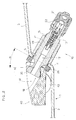
- Fig. I shows a portion of a rim bead of a vehicle wheel seen from the face suitable to receive the edges of a tyre (not shown in the Figs).
- the bead is indicated as a whole with the reference number 1.
- the bead 1 comprises a recessed part 2 and a raised part 3 in relation to the recessed part 2.
- the recessed part 2 is connected to the raised part 3 by means of a slanting or inclined wall 4.
- the inclined wall 4 of the bead has an angle of inclination a in relation to a radial straight line n running towards the centre of the wheel.
- the angle ⁇ varies according to the type of rim employed and generally may be between 10° and 30°.
- a through hole 5 is made suitable to receive a valve for inflation of the tyre, indicated as a whole with the reference number 10.
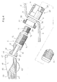
- the valve 10 comprises a valve body 11 with a substantially cylindrical shape, with an external diameter slightly smaller than the diameter of the hole 5.
- the valve body 11 is internally hollow and axially has a through duct 12 fitted inside which is an operating mechanism of the valve 13 per se known and therefore not illustrated in detail.
- the valve body 11 comprises a cylindrical central portion 14 provided with an external thread 15. From the central portion 15 of the valve body a cylindrical pin 16 with a smaller diameter extends at the front and axially to form the head of the valve. The external surface of the cylindrical pin 16 is provided with an external thread 17.
- a substantially rounded tail part 18 extends from the rear of the central portion 15 of the valve body.
- the tail 18 has a narrower part 19 and a tapered part 20 with an increasing diameter going from the narrower part 19 towards the rear end.
- the tapered part 20 of the tail 18 of the valve body has a substantially truncated spherical or truncated conical configuration.
- the valve 10 also comprises a covering cap 21 provided with an internal thread 22 suitable to screw into the external thread 17 of the pin 16 of the head of the valve body.
- the valve 10 also comprises a threaded ring nut 23 with an internal thread 24 suitable to screw into the external thread 15 of the central part 14 of the valve body.
- the ring nut 23 has a substantially cylindrical shape with an external diameter larger than the diameter of the hole 5 of the slanting wall 4 of the rim bead.
- the front part of the threaded ring nut 23 facing the head of the valve has an external profile cut in the shape of a hexagon nut 25 to be rotated by specific tools.
- the valve 10 also comprises a gasket 26 with a substantially discoid shape with a through hole 29 suitable to receive the valve body.
- the gasket 26 has a first disc with a larger diameter 27 and a second disc with a smaller diameter 28. In this way on the disc with the larger diameter 27 an annular contact surface 30 is defined.
- the disc with the larger diameter 27 has a diameter larger than the diameter of the hole 5 of the slanting wall 4 of the bead 1 and the disc with the smaller diameter 28 has a diameter substantially equal to the diameter of the hole 5 so that it can be force fit inside this to guarantee seal with the edges of the hole 5.
- the gasket 26 is fitted to the central part 14 of the valve body.
- the rear part of the central part 14 of the body has, on its external surface, a portion in which the thread 15 is not provided.
- the valve 1 is suitable to hold in position, on the recessed part 2 of the rim bead 1, a sensor, indicated as a whole with the reference number 40.
- a sensor indicated as a whole with the reference number 40.
- the sensitive part suitable to detect state parameters of the tyre, such as pressure and temperature, and the transmission part suitable to transmit electronic signals indicative of the parameters detected to a receiving apparatus fitted on the vehicle.
- the sensor 40 has a body 41 in the shape of a substantially parallelepiped plate with a rounded front surface 42.
- the body 41 of the sensor is supported by two feet 43 rested on the two side walls of the body of the sensor.
- the feet 43 have a substantially discoid configuration so that they guarantee a substantially rounded resting part to adapt to the various curves of the profile of the recessed part 2 of the bead intended to receive the sensor 40. Moreover, the feet 43 may be produced in elastic material, to yield elastically and adapt to the configuration of the recessed part 2 of the bead.
- the central position in the body 41 is provided with a slot 44 that extends from the top wall 48 of the body 41 to the front wall 42.
- the slot 44 is defined by an elliptical hole 45 on the top surface 48 communicating with a circular hole 46 on the front surface 42.
- a narrower part 47 of the body 41 of the sensor is provided between the elliptical hole 45 of the top wall 48 and the circular hole 46 of the front wall 42.
- the tail part 18 of the valve body 11 can be coupled inside the slot 44 of the body 41 of the sensor. More precisely, the tapered part 20 of the tail part 18 of the valve body is held by the narrower part 47 of the body 41 of the sensor and the narrower part 19 of the tail 18 of the valve body projects from the hole 46 of the front surface 42 of the sensor body.
- a spherical fit is defined between the valve 10 and the sensor 40. That is to say, the sensor 40 is free to rotate around the spherical surface of the tail 18 of the valve 10, in a relation of spherical fit.
- the head part 16 of the valve body 11 is inserted into the hole 5 of the inclined wall 4 of the rim bead 1. In this way the head 16 and the central part 14 of the valve body project behind the bead 1 to be accessible to the user and the sensor 40 is set on the part of the bead 1 facing the inner chamber of the tyre.
- the gasket 26 guarantees the air seal around the hole 5.
- the sensor 40 self-positions itself on the recessed part 2 of the bead 1 and at the same time is locked in position abutting against the gasket 26.
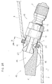
- Fig. 2 A shows a bead with an inclined part 4 with an angle of inclination ⁇ differing from the angle ⁇ in the example in Fig. 2.
- the sensor thanks to spherical fit between the tail 18 of the valve 10 and the slot 44 of the sensor 40 and thanks to the discoid feet 43 of the sensor, the sensor adapts perfectly to the configuration of the bead 1.
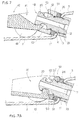
- Fig. 7 shows a variant, in which between the gasket 26 and the edge of the sensor 40 a washer 50 is interposed fitted around the valve body 11.
- a washer 50 is interposed fitted around the valve body 11.
- the washer 50 may be produced in metal material, such as aluminium.
- the washer 50 has an axial through hole 52 through which the body 11 of the valve may pass.
- a gasket 54 such as an O-ring, interposed between the body 11 and the washer 50 to guarantee correct seal of the washer.
- the washer 50 has a flat lower surface 51 that abuts against the top surface of the gasket 26.
- the external edge part of the sensor around the slot 44 is substantially convex. Consequently the washer 50 has a substantially concave top surface 53 to engage, in spherical fit relation, with the external edge part of the sensor 40.
- Fig. 7A shows an example in which the external edge portion of the sensor around the slot 44 has a substantially concave configuration.
- the washer 50 has a substantially convex top surface 53', in the shape of a spherical cap, to coupling, in spherical fit relation, with the external edge portion of the sensor 40.
- the fitting of the washer 50 allows perfect connection of the valve with the sensor and allows the valve to be adapted to sensors with different configurations. Moreover, the washer 50 allows correct compression of the gasket 26 on the entire contact surface between washer and gasket.
Priority Applications (1)
| Application Number | Priority Date | Filing Date | Title |
|---|---|---|---|
| EP02425117A EP1340630A1 (de) | 2002-03-01 | 2002-03-01 | Verbindungssystem zwischen Ventil und Sensor für Fahrzeugreifen |
Applications Claiming Priority (1)
| Application Number | Priority Date | Filing Date | Title |
|---|---|---|---|
| EP02425117A EP1340630A1 (de) | 2002-03-01 | 2002-03-01 | Verbindungssystem zwischen Ventil und Sensor für Fahrzeugreifen |
Publications (1)
| Publication Number | Publication Date |
|---|---|
| EP1340630A1 true EP1340630A1 (de) | 2003-09-03 |
Family
ID=27675816
Family Applications (1)
| Application Number | Title | Priority Date | Filing Date |
|---|---|---|---|
| EP02425117A Withdrawn EP1340630A1 (de) | 2002-03-01 | 2002-03-01 | Verbindungssystem zwischen Ventil und Sensor für Fahrzeugreifen |
Country Status (1)
| Country | Link |
|---|---|
| EP (1) | EP1340630A1 (de) |
Cited By (7)
| Publication number | Priority date | Publication date | Assignee | Title |
|---|---|---|---|---|
| GB2407383A (en) * | 2003-10-24 | 2005-04-27 | Lear Corp | Tyre pressure monitoring apparatus mounting arrangement |
| US7086412B2 (en) * | 2003-10-24 | 2006-08-08 | Lear Corporation | Snap-in grommet for a valve steam assembly |
| US7086411B2 (en) * | 2003-10-24 | 2006-08-08 | Lear Corporation | Snap-in grommet for a valve stem assembly |
| DE102006044867A1 (de) * | 2006-09-22 | 2008-04-03 | Siemens Ag | Gehäuse für Radelektroniken |
| FR2954733A1 (fr) * | 2009-12-28 | 2011-07-01 | Continental Automotive France | Unite electronique de mesure de parametres de fonctionnement d'une roue de vehicule,comprenant un boitier electronique et une valve de gonflage |
| CN104527343A (zh) * | 2014-04-29 | 2015-04-22 | 上海为彪汽配制造有限公司 | 卡合式胎压感测装置 |
| CN110843429A (zh) * | 2018-08-20 | 2020-02-28 | 保隆霍富(上海)电子有限公司 | Tpms发射机的固定结构及装配结构 |
Citations (5)
| Publication number | Priority date | Publication date | Assignee | Title |
|---|---|---|---|---|
| EP0751017A2 (de) * | 1995-06-26 | 1997-01-02 | Alligator Ventilfabrik GmbH | Vorrichtung zum Messen des Reifendruckes in einem Luftreifen eines Fahrzeuges |
| DE19610376A1 (de) * | 1996-03-16 | 1997-09-18 | Continental Ag | Vorrichtung zur Befestigung eines Sensors an einer Felge |
| EP0816136A2 (de) * | 1996-07-01 | 1998-01-07 | Continental Aktiengesellschaft | Befestigungsvorrichtung für ein Elektronikmodul |
| DE20110759U1 (de) * | 2001-06-26 | 2002-02-14 | Beru Ag | Rad für Fahrzeuge mit Luftreifen und Anordnung aus einem Ventil, einer Vorrichtung zum Messen des Reifendruckes und einer sie im Luftreifen haltenden Feder |
| DE10047853A1 (de) * | 2000-08-11 | 2002-02-28 | Alligator Ventilfab Gmbh | Vorrichtung zum Messen des Reifendruckes in einem Luftreifen eines Fahrzeuges |
-
2002
- 2002-03-01 EP EP02425117A patent/EP1340630A1/de not_active Withdrawn
Patent Citations (5)
| Publication number | Priority date | Publication date | Assignee | Title |
|---|---|---|---|---|
| EP0751017A2 (de) * | 1995-06-26 | 1997-01-02 | Alligator Ventilfabrik GmbH | Vorrichtung zum Messen des Reifendruckes in einem Luftreifen eines Fahrzeuges |
| DE19610376A1 (de) * | 1996-03-16 | 1997-09-18 | Continental Ag | Vorrichtung zur Befestigung eines Sensors an einer Felge |
| EP0816136A2 (de) * | 1996-07-01 | 1998-01-07 | Continental Aktiengesellschaft | Befestigungsvorrichtung für ein Elektronikmodul |
| DE10047853A1 (de) * | 2000-08-11 | 2002-02-28 | Alligator Ventilfab Gmbh | Vorrichtung zum Messen des Reifendruckes in einem Luftreifen eines Fahrzeuges |
| DE20110759U1 (de) * | 2001-06-26 | 2002-02-14 | Beru Ag | Rad für Fahrzeuge mit Luftreifen und Anordnung aus einem Ventil, einer Vorrichtung zum Messen des Reifendruckes und einer sie im Luftreifen haltenden Feder |
Cited By (12)
| Publication number | Priority date | Publication date | Assignee | Title |
|---|---|---|---|---|
| GB2407383A (en) * | 2003-10-24 | 2005-04-27 | Lear Corp | Tyre pressure monitoring apparatus mounting arrangement |
| US6945104B2 (en) | 2003-10-24 | 2005-09-20 | Lear Corporation | Attachment mechanism for a tire monitoring system |
| GB2407383B (en) * | 2003-10-24 | 2006-03-08 | Lear Corp | Attachment mechanism for a tire monitoring system |
| US7086412B2 (en) * | 2003-10-24 | 2006-08-08 | Lear Corporation | Snap-in grommet for a valve steam assembly |
| US7086411B2 (en) * | 2003-10-24 | 2006-08-08 | Lear Corporation | Snap-in grommet for a valve stem assembly |
| DE102006044867A1 (de) * | 2006-09-22 | 2008-04-03 | Siemens Ag | Gehäuse für Radelektroniken |
| FR2954733A1 (fr) * | 2009-12-28 | 2011-07-01 | Continental Automotive France | Unite electronique de mesure de parametres de fonctionnement d'une roue de vehicule,comprenant un boitier electronique et une valve de gonflage |
| WO2011079888A1 (fr) * | 2009-12-28 | 2011-07-07 | Continental Automotive France | Unite electronique de mesure de parametres de fonctionnement d'une roue de vehicule, comprenant un boitier electronique et une valve de gonflage |
| US8839667B2 (en) | 2009-12-28 | 2014-09-23 | Continental Automotive France | Electronic unit for measuring the operation parameters of a vehicle wheel including an electronic housing and an inflation valve |
| CN104527343A (zh) * | 2014-04-29 | 2015-04-22 | 上海为彪汽配制造有限公司 | 卡合式胎压感测装置 |
| CN104527343B (zh) * | 2014-04-29 | 2017-01-11 | 上海为彪汽配制造有限公司 | 卡合式胎压感测装置 |
| CN110843429A (zh) * | 2018-08-20 | 2020-02-28 | 保隆霍富(上海)电子有限公司 | Tpms发射机的固定结构及装配结构 |
Similar Documents
| Publication | Publication Date | Title |
|---|---|---|
| US7536904B1 (en) | Tire pressure detector and valve stem assembly | |
| JP3759890B2 (ja) | 空気入りタイヤの状態を調べるための状態センサ | |
| US7017403B2 (en) | Vehicle wheel comprising a tire and an assembly consisting of a valve a device for measuring the tire pressure and a spring for holding said device in the tire | |
| US7870866B2 (en) | Valve stem assembly for clamping a tire pressure detector | |
| US8245747B2 (en) | Tire valve and process for removing it | |
| US11970029B2 (en) | Adapter, tyre parameter monitoring system and method for mounting a tyre parameter monitoring system onto a wheel rim | |
| US7775095B2 (en) | Valve stem with a connecting cap for a tire pressure detector | |
| US10549586B1 (en) | Electronic unit for measuring operating parameters of a vehicle wheel | |
| EP1340630A1 (de) | Verbindungssystem zwischen Ventil und Sensor für Fahrzeugreifen | |
| US20240066931A1 (en) | Tubeless valve assembly | |
| US6655203B2 (en) | Tire-condition sensor having positioning bolts for adjustably positioning the sensor in a fixed position on a wheel rim of a pneumatic tire | |
| JP4021846B2 (ja) | 自動車のホイールリムにケーシングを取り付けるための装置及び関連する取り付け方法 | |
| US7040155B1 (en) | Sensor housing fastening arrangement in wheels with pneumatic tires | |
| JP6704986B2 (ja) | タイヤ状態検出装置 | |
| US20030046994A1 (en) | Pressure detector adapted to be mounted in a tire | |
| US20030154779A1 (en) | Combined valve-pressure measurement device for a tyre | |
| EP3919297A2 (de) | Reifenfüllventil mit einstellsystem für einen tpms-sensor | |
| US11724553B2 (en) | Valve system, tire parameter monitoring system and method for mounting a tire parameter monitoring system onto a wheel rim of a vehicle | |
| US6966331B2 (en) | Valve stem adaptor | |
| JP3141775U (ja) | タイヤ圧検出器・バルブステムアセンブリ | |
| US5741103A (en) | Securing structure for air valves | |
| US11760138B2 (en) | Tire inflation valve equipped with adjusting system for a TPMS sensor | |
| JP4615577B2 (ja) | タイヤ圧検出器をクランプ固定するためのバルブステムアセンブリ | |
| US6739187B2 (en) | Device for articulating a tire-pressure sensor on a motor vehicle rim | |
| CN210911904U (zh) | 一种汽车tpms气门嘴用垫片及气门嘴安装结构 |
Legal Events
| Date | Code | Title | Description |
|---|---|---|---|
| PUAI | Public reference made under article 153(3) epc to a published international application that has entered the european phase |
Free format text: ORIGINAL CODE: 0009012 |
|
| AK | Designated contracting states |
Kind code of ref document: A1 Designated state(s): AT BE CH CY DE DK ES FI FR GB GR IE IT LI LU MC NL PT SE TR |
|
| AX | Request for extension of the european patent |
Extension state: AL LT LV MK RO SI |
|
| 17P | Request for examination filed |
Effective date: 20040116 |
|
| AKX | Designation fees paid |
Designated state(s): AT BE CH CY DE DK ES FI FR GB GR IE IT LI LU MC NL PT SE TR |
|
| 17Q | First examination report despatched |
Effective date: 20050704 |
|
| STAA | Information on the status of an ep patent application or granted ep patent |
Free format text: STATUS: THE APPLICATION IS DEEMED TO BE WITHDRAWN |
|
| 18D | Application deemed to be withdrawn |
Effective date: 20051115 |