EP1339989B1 - Klammersystem zur befestigung eines anbauteils an einem trägerteil - Google Patents
Klammersystem zur befestigung eines anbauteils an einem trägerteil Download PDFInfo
- Publication number
- EP1339989B1 EP1339989B1 EP01994687A EP01994687A EP1339989B1 EP 1339989 B1 EP1339989 B1 EP 1339989B1 EP 01994687 A EP01994687 A EP 01994687A EP 01994687 A EP01994687 A EP 01994687A EP 1339989 B1 EP1339989 B1 EP 1339989B1
- Authority
- EP
- European Patent Office
- Prior art keywords
- bent
- clip
- opening
- retaining rib
- attachment
- Prior art date
- Legal status (The legal status is an assumption and is not a legal conclusion. Google has not performed a legal analysis and makes no representation as to the accuracy of the status listed.)
- Expired - Lifetime
Links
- 210000000078 claw Anatomy 0.000 claims abstract description 17
- 239000012858 resilient material Substances 0.000 claims abstract description 3
- 238000003780 insertion Methods 0.000 claims description 7
- 230000037431 insertion Effects 0.000 claims description 7
- 230000003014 reinforcing effect Effects 0.000 claims description 5
- 230000001154 acute effect Effects 0.000 claims description 2
- 210000002414 leg Anatomy 0.000 description 33
- 230000000694 effects Effects 0.000 description 3
- 229910000639 Spring steel Inorganic materials 0.000 description 2
- 238000005452 bending Methods 0.000 description 2
- 230000005489 elastic deformation Effects 0.000 description 1
- 238000004080 punching Methods 0.000 description 1
- 125000006850 spacer group Chemical group 0.000 description 1
- 210000000689 upper leg Anatomy 0.000 description 1
Images
Classifications
-
- F—MECHANICAL ENGINEERING; LIGHTING; HEATING; WEAPONS; BLASTING
- F16—ENGINEERING ELEMENTS AND UNITS; GENERAL MEASURES FOR PRODUCING AND MAINTAINING EFFECTIVE FUNCTIONING OF MACHINES OR INSTALLATIONS; THERMAL INSULATION IN GENERAL
- F16B—DEVICES FOR FASTENING OR SECURING CONSTRUCTIONAL ELEMENTS OR MACHINE PARTS TOGETHER, e.g. NAILS, BOLTS, CIRCLIPS, CLAMPS, CLIPS OR WEDGES; JOINTS OR JOINTING
- F16B5/00—Joining sheets or plates, e.g. panels, to one another or to strips or bars parallel to them
- F16B5/06—Joining sheets or plates, e.g. panels, to one another or to strips or bars parallel to them by means of clamps or clips
- F16B5/0607—Joining sheets or plates, e.g. panels, to one another or to strips or bars parallel to them by means of clamps or clips joining sheets or plates to each other
- F16B5/0621—Joining sheets or plates, e.g. panels, to one another or to strips or bars parallel to them by means of clamps or clips joining sheets or plates to each other in parallel relationship
- F16B5/065—Joining sheets or plates, e.g. panels, to one another or to strips or bars parallel to them by means of clamps or clips joining sheets or plates to each other in parallel relationship the plates being one on top of the other and distanced from each other, e.g. by using protrusions to keep contact and distance
-
- F—MECHANICAL ENGINEERING; LIGHTING; HEATING; WEAPONS; BLASTING
- F16—ENGINEERING ELEMENTS AND UNITS; GENERAL MEASURES FOR PRODUCING AND MAINTAINING EFFECTIVE FUNCTIONING OF MACHINES OR INSTALLATIONS; THERMAL INSULATION IN GENERAL
- F16B—DEVICES FOR FASTENING OR SECURING CONSTRUCTIONAL ELEMENTS OR MACHINE PARTS TOGETHER, e.g. NAILS, BOLTS, CIRCLIPS, CLAMPS, CLIPS OR WEDGES; JOINTS OR JOINTING
- F16B2/00—Friction-grip releasable fastenings
- F16B2/20—Clips, i.e. with gripping action effected solely by the inherent resistance to deformation of the material of the fastening
- F16B2/22—Clips, i.e. with gripping action effected solely by the inherent resistance to deformation of the material of the fastening of resilient material, e.g. rubbery material
- F16B2/24—Clips, i.e. with gripping action effected solely by the inherent resistance to deformation of the material of the fastening of resilient material, e.g. rubbery material of metal
- F16B2/241—Clips, i.e. with gripping action effected solely by the inherent resistance to deformation of the material of the fastening of resilient material, e.g. rubbery material of metal of sheet metal
-
- F—MECHANICAL ENGINEERING; LIGHTING; HEATING; WEAPONS; BLASTING
- F16—ENGINEERING ELEMENTS AND UNITS; GENERAL MEASURES FOR PRODUCING AND MAINTAINING EFFECTIVE FUNCTIONING OF MACHINES OR INSTALLATIONS; THERMAL INSULATION IN GENERAL
- F16B—DEVICES FOR FASTENING OR SECURING CONSTRUCTIONAL ELEMENTS OR MACHINE PARTS TOGETHER, e.g. NAILS, BOLTS, CIRCLIPS, CLAMPS, CLIPS OR WEDGES; JOINTS OR JOINTING
- F16B5/00—Joining sheets or plates, e.g. panels, to one another or to strips or bars parallel to them
- F16B5/06—Joining sheets or plates, e.g. panels, to one another or to strips or bars parallel to them by means of clamps or clips
- F16B5/0607—Joining sheets or plates, e.g. panels, to one another or to strips or bars parallel to them by means of clamps or clips joining sheets or plates to each other
- F16B5/0621—Joining sheets or plates, e.g. panels, to one another or to strips or bars parallel to them by means of clamps or clips joining sheets or plates to each other in parallel relationship
- F16B5/0657—Joining sheets or plates, e.g. panels, to one another or to strips or bars parallel to them by means of clamps or clips joining sheets or plates to each other in parallel relationship at least one of the plates providing a raised structure, e.g. of the doghouse type, for connection with the clamps or clips of the other plate
-
- F—MECHANICAL ENGINEERING; LIGHTING; HEATING; WEAPONS; BLASTING
- F16—ENGINEERING ELEMENTS AND UNITS; GENERAL MEASURES FOR PRODUCING AND MAINTAINING EFFECTIVE FUNCTIONING OF MACHINES OR INSTALLATIONS; THERMAL INSULATION IN GENERAL
- F16B—DEVICES FOR FASTENING OR SECURING CONSTRUCTIONAL ELEMENTS OR MACHINE PARTS TOGETHER, e.g. NAILS, BOLTS, CIRCLIPS, CLAMPS, CLIPS OR WEDGES; JOINTS OR JOINTING
- F16B5/00—Joining sheets or plates, e.g. panels, to one another or to strips or bars parallel to them
- F16B5/06—Joining sheets or plates, e.g. panels, to one another or to strips or bars parallel to them by means of clamps or clips
- F16B5/0607—Joining sheets or plates, e.g. panels, to one another or to strips or bars parallel to them by means of clamps or clips joining sheets or plates to each other
- F16B5/0614—Joining sheets or plates, e.g. panels, to one another or to strips or bars parallel to them by means of clamps or clips joining sheets or plates to each other in angled relationship
-
- Y—GENERAL TAGGING OF NEW TECHNOLOGICAL DEVELOPMENTS; GENERAL TAGGING OF CROSS-SECTIONAL TECHNOLOGIES SPANNING OVER SEVERAL SECTIONS OF THE IPC; TECHNICAL SUBJECTS COVERED BY FORMER USPC CROSS-REFERENCE ART COLLECTIONS [XRACs] AND DIGESTS
- Y10—TECHNICAL SUBJECTS COVERED BY FORMER USPC
- Y10T—TECHNICAL SUBJECTS COVERED BY FORMER US CLASSIFICATION
- Y10T24/00—Buckles, buttons, clasps, etc.
- Y10T24/30—Trim molding fastener
- Y10T24/304—Resilient metal type
-
- Y—GENERAL TAGGING OF NEW TECHNOLOGICAL DEVELOPMENTS; GENERAL TAGGING OF CROSS-SECTIONAL TECHNOLOGIES SPANNING OVER SEVERAL SECTIONS OF THE IPC; TECHNICAL SUBJECTS COVERED BY FORMER USPC CROSS-REFERENCE ART COLLECTIONS [XRACs] AND DIGESTS
- Y10—TECHNICAL SUBJECTS COVERED BY FORMER USPC
- Y10T—TECHNICAL SUBJECTS COVERED BY FORMER US CLASSIFICATION
- Y10T24/00—Buckles, buttons, clasps, etc.
- Y10T24/30—Trim molding fastener
- Y10T24/304—Resilient metal type
- Y10T24/307—Sheet metal formed
Definitions
- the invention relates to a stapling system for attaching an attachment to a Carrier part, consisting of a connecting clip made of resilient material, a Attachment and a support member with an opening, wherein the connection bracket to a retaining rib of the attachment firmly clamped and in a substantially rectangular Opening of the support member can be inserted and thereby deformed resiliently, that this clip at the edges of this opening with the carrier part in a non-positive Connection reaches, with the connection bracket in the unassembled Has state two of a central web of spring legs bent towards each other, having obliquely bent claws, which after insertion the retaining rib abut resiliently on the side surfaces thereof.
- the actual purpose of the terminal namely the attachment of the attachment to a carrier part, serves only the middle, longer pair of legs.
- This is the middle one Width of the longer pair of legs larger by a certain amount than the corresponding one clear width of a slot-shaped opening in the support part.
- the attachment is the retaining rib with the clamp mounted thereon under elastic Deformation of the middle leg pair in the slot-shaped opening of the Carrier part inserted until the opposite, obtuse Areas of the pair of legs are behind the inner edge of the opening and the Abut leg surfaces after spring-back on the inner edge.
- this clamp does not guarantee an effective secure fit on the Holding rib of the attachment, since they only there by the inward pressure force of the leg pair is held. For this reason, also had the lateral shorter pairs of legs are additionally provided with their holding claws. Because the Holding claws by the relatively short spring length of the clamping legs the bending To oppose a great resistance, a relatively large effort is required around the retaining rib between the retaining claws until it stops in the Reason to press the terminal.
- the object of the invention is a versatile and easy to install Clamping system for connecting components, in which with as possible simple means a really secure fit of the clamp on the support part and Thus, a secure connection of the component can be achieved with the support member.
- connection clip is simple Achieves that the retaining rib easily through the recess between the Pressing claws through and when inserting the clip in the opening of the Carrier part the claws by squeezing the backward bent spring legs additionally be pressed against the side walls of the retaining rib, so that the clamping effect of the claws is enhanced. This will be opposite the aforementioned prior art even higher holding forces and thus undoubtedly an even more secure fit of the bracket achieved.
- the outer legs are expediently alternately made of three at obtuse angles formed inwardly and outwardly bent sections, wherein the Crease line between the second and the third section each have a latching groove for forms the locking edges of the opening.
- first section of advantage if this one over the rounded end Having sufficient, substantially rectangular recess. This gives the first section of the spring legs by the only remaining narrow Spring bars a greater elasticity and leaves the connection bracket easier in the Insert the opening of the carrier plate and, if necessary, remove it again.
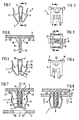
- the present clamp system is used to attach an attachment 6 to a support member 7 by means of a connection clip 1, which is clamped to a retaining rib 8 of the attachment 6 .
- the so clamped connection bracket 1 is then inserted in a substantially rectangular opening 9 of the support member 7 .
- the connecting clamp 1 is deformed resiliently so that the clip 1 of this opening 9 is applied to the edges 10 to the support part 7 in a non-positive connection.
- the connecting bracket 1 is made of an originally rectangular piece of spring steel sheet, wherein the connecting bracket 1 in the unmounted state has two of a central web 2 of mutually bent spring leg 3 . These are bent at their free, almost touching ends 4 outwards and backwards so that the outer legs 5 formed in the side view of FIG. 1 form a wedge-shaped profile.
- the outer spring legs 5 are, as can be seen from Figure 5 , formed of three sections, of which the first portion 11 is bent from the lower free end 4 of an acute angle to the outside.
- the second, central portion 12 adjoins it at an obtuse angle inwardly, while the third portion 13 is again bent outwards at an obtuse angle.
- the crease line between the second portion 12 and the third portion 13 each form a latching groove 14 which BEZW after the insertion of the connecting clip 1 in the opening 9 of the support member 7 at the locking edges 10 . locks.
- the connecting bracket 1 For safe and permanent connection of the connecting bracket 1 with the attachment 6 , the latter has a retaining rib 8 , while in the central web 2 of the connecting clip 1, a recess 15 is cut, which corresponds in cross section to the retaining rib 8 in the clear dimensions.
- a recess 15 is cut, which corresponds in cross section to the retaining rib 8 in the clear dimensions.
- the lower end 4 of the spring leg 3 obliquely bent to each other claws 16 are formed, which create resiliently on the side surfaces 17 of the retaining rib 8 .
- the holding rib 8 is supported centrally on both sides with a triangular reinforcing rib 18 against the attachment 6 . Accordingly, in the inner spring legs 3 on both sides of the recess 15 from the edges 19 of a respective slot 20 punched out, which is used after insertion of the retaining rib 8 in the connecting clip 1 for receiving the reinforcing rib 18 .
- support ribs 21 are also integrally formed on the attachment 6 at a distance from this, which simultaneously engage on the support part 7 when the latching groove 14 engages in the opening 9 and thus act as a spacer between the support part 7 and the attachment 6 ,
- the distance between the two support ribs 21 is dimensioned so that the upper portions 13 of the outer spring legs 5 in the relaxed state of the connecting bracket 1 after insertion of the retaining rib 8 between the support ribs 21 have enough space.
- this section has a substantially rectangular punched- 22 , which extends beyond the round curved end 4 also in the inner spring leg 3 .
Landscapes
- Engineering & Computer Science (AREA)
- General Engineering & Computer Science (AREA)
- Mechanical Engineering (AREA)
- Clamps And Clips (AREA)
- Insertion Pins And Rivets (AREA)
Description
- Fig. 1
- Eine beim vorliegenden Klammersystem verwendete bevorzugte Ausführungsform der Verbindungsklammer in Seitenansicht,
- Fig. 2
- Die gleiche Verbindungsklammer in Vorderansicht,
- Fig. 3
- Die gleiche Verbindungsklammer in Draufsicht,
- Fig. 4
- Einen Schnitt durch die Verbindungsklammer gemäß IV-IV in Fig.1,
- Fig. 5
- Einen Schnitt durch die Verbindungsklammer gemäß V-V in Fig.2
- Fig. 6
- Ein Ausschnitt eines Anbauteils mit einer zum Einführen in die Verbindungsklammer ausgerichteten Halterippe,
- Fig. 7
- Die an der Halterippe aufmontierte Verbindungsklammer im Schnitt gemäß VII - VII in Fig. 3, ausgerichtet zum Einführen in die Befestigungsöffnung eines Trägerteils und
- Fig. 8
- Das gleiche Bild wie Figur 7 nach der erfindungsgemäß hergestellten Verbindung zwischen Anbauteil und Trägerteil.
- 1
- Verbindungsklammer
- 2
- Mittelsteg
- 3
- Federschenkel
- 4
- Freies Ende
- 5
- Äußere Schenkel
- 6
- Anbauteil
- 7
- Trägerteil
- 8
- Halterippe
- 9
- Öffnung
- 10
- Rastkanten
- 11
- Erster Abschnitt
- 12
- Zweiter Abschnitt
- 13
- Dritter Abschnitt
- 14
- Rastrille
- 15
- Aussparung
- 16
- Krallen
- 17
- Seitenflächen
- 18
- Verstärkungsrippe
- 19
- Kante (der Aussparung)
- 20
- Schlitz
- 21
- Stützrippe
- 22
- Ausstanzung
Claims (5)
- Klammersystem zur Befestigung eines Anbauteils an einem Trägerteil, bestehend aus einer Verbindungsklammer (1) aus federndem Material, einem Anbauteil (6) und einem Trägerteil (7) mit einer Öffnung (9), wobei die Verbindungsklammer (1) an einer Halterippe (8) des Anbauteils (6) festklemmbar und in die im wesentlichen rechteckige Öffnung (9) des Trägerteils (7) einsteckbar ist und sich dabei derart federnd verformt, dass die Klammer (1) an den Kanten (10) dieser Öffnung (9) mit dem Trägerteil (7) in eine kraftschlüssige Verbindung gelangt, wobei die Verbindungsklammer (1) im nicht montierten Zustand zwei von einem Mittelsteg (2) aus aufeinander zu gebogene Federschenkel (3) besitzt, die schräg aufeinander zu gebogene Krallen (16) aufweisen, welche nach dem Einführen der Halterippe (8) federnd an deren Seitenflächen (17) anliegen,
dadurch gekennzeichnet, die freien Enden (4) der Federschenkel (3) derart nach außen und rückwärts gebogen sind, dass die dadurch gebildeten äußeren Schenkel (5) zwischen den Kanten (10) der Öffnung (9) federnd zusammendrückbar und einrastbar sind, und dass der Mittelsteg (2) eine Aussparung (15) zum Einführen der Halterippe (8) besitzt. - Klammersystem nach Anspruch 1, dadurch gekennzeichnet, daß die schräg aufeinanderzu gebogenen Krallen (16) kurz vor dem freien Ende (4) der inneren Federschenkel (3) angeordnet sind.
- Klammersystem nach Anspruch 1 oder 2, dadurch gekennzeichnet, daß in den inneren Federschenkeln (3) auf beiden Seiten der Aussparung (15) von deren Kanten (19) aus je einen Schlitz (20) ausgestanzt ist, welcher zur Aufnahme einer entsprechend starken Verstärkungsrippe (18) zwischen Anbauteil (6) und Halterippe (8) dient.
- Klammersystem nach einem der Ansprüche 1 bis 3, dadurch gekennzeichnet, daß die äußeren Federschenkel (5) aus drei Abschnitten gebildet sind, von denen der erste Abschnitt (11) vom freien Ende (4) aus spitzwinklig nach außen abgebogen ist, der zweite Abschnitt (12) im stumpfen Winkel nach innen und der dritte Abschnitt (13) anschließend nochmals im stumpfen Winkel nach außen gebogen ist, wobei die Knicklinie zwischen dem zweiten Abschnitt (12) und dem dritten Abschnitt (13) die Rastrinne (14) für die Kanten (10) der Öffnung (9) bildet.
- Klammersystem nach Anspruch 4, dadurch gekennzeichnet, daß der erste Abschnitt (11) bis über das rund gebogene freie Ende (4) hinaus eine im wesentlichen rechteckige Ausstanzung (22) aufweist.
Applications Claiming Priority (3)
| Application Number | Priority Date | Filing Date | Title |
|---|---|---|---|
| DE10059522A DE10059522A1 (de) | 2000-11-30 | 2000-11-30 | Klammersystem zur Befestigung eines Anbauteils auf einem Trägerteil |
| DE10059522 | 2000-11-30 | ||
| PCT/EP2001/013489 WO2002044570A1 (de) | 2000-11-30 | 2001-11-21 | Klammersystem zur befestigung eines anbauteils an einem trägerteil |
Publications (2)
| Publication Number | Publication Date |
|---|---|
| EP1339989A1 EP1339989A1 (de) | 2003-09-03 |
| EP1339989B1 true EP1339989B1 (de) | 2005-07-06 |
Family
ID=7665273
Family Applications (1)
| Application Number | Title | Priority Date | Filing Date |
|---|---|---|---|
| EP01994687A Expired - Lifetime EP1339989B1 (de) | 2000-11-30 | 2001-11-21 | Klammersystem zur befestigung eines anbauteils an einem trägerteil |
Country Status (9)
| Country | Link |
|---|---|
| US (1) | US6918162B2 (de) |
| EP (1) | EP1339989B1 (de) |
| AT (1) | ATE299244T1 (de) |
| CZ (1) | CZ20031389A3 (de) |
| DE (2) | DE10059522A1 (de) |
| ES (1) | ES2243592T3 (de) |
| HU (1) | HUP0302280A3 (de) |
| PL (1) | PL199231B1 (de) |
| WO (1) | WO2002044570A1 (de) |
Families Citing this family (15)
| Publication number | Priority date | Publication date | Assignee | Title |
|---|---|---|---|---|
| US7120971B2 (en) | 2001-03-02 | 2006-10-17 | Newfrey Llc | Low insertion effort u-base retainer |
| WO2003100267A1 (en) | 2002-05-28 | 2003-12-04 | Newfrey Llc | Resilient clip fastener and method of manufacturing the same |
| TW200623980A (en) * | 2004-12-31 | 2006-07-01 | Tatung Co Ltd | Springy contact |
| FR2890129B1 (fr) * | 2005-08-29 | 2007-11-30 | Attax Sarl | Attache elastique pour la fixation de deux pieces l'une sur l'autre. |
| DE102006026684B4 (de) * | 2006-06-08 | 2016-03-17 | Lisa Dräxlmaier GmbH | Zierteil |
| US7681843B2 (en) * | 2007-05-24 | 2010-03-23 | Cambridge Silversmiths Ltd., Inc. | Display and retaining clip |
| EP2268166B1 (de) * | 2008-03-31 | 2014-12-17 | TS Tech Co., Ltd. | Clipmontagesitz und fahrzeuginnenraumkomponente |
| FR2930976B1 (fr) * | 2008-05-07 | 2013-06-21 | Raymond A & Cie | Agrafe de fixation de deux pieces l'une sur l'autre |
| US7828372B2 (en) * | 2008-06-12 | 2010-11-09 | Honda Motor Co., Ltd. | Mounting arrangement for mounting cladding to vehicle body |
| USD722492S1 (en) * | 2013-05-25 | 2015-02-17 | Dieter Ramsauer | Holding clamp |
| USD759476S1 (en) * | 2013-06-18 | 2016-06-21 | Daiwa Kasei Kogyo Kabushiki Kaisha | Clip |
| KR20190127824A (ko) * | 2017-03-23 | 2019-11-13 | 일리노이즈 툴 워크스 인코포레이티드 | 선형으로 조정 가능한 클립 조립체 |
| US10442329B2 (en) * | 2017-11-09 | 2019-10-15 | B/E Aerospace Fischer Gmbh | Clip and method for attaching and tensioning seat dress covers |
| US10973321B2 (en) | 2018-09-04 | 2021-04-13 | Steelcase Inc. | Workspace system and components and method for the use thereof |
| CN112932279A (zh) * | 2021-02-10 | 2021-06-11 | 青岛海尔智慧厨房电器有限公司 | 一种连接支架及烘烤装置 |
Family Cites Families (9)
| Publication number | Priority date | Publication date | Assignee | Title |
|---|---|---|---|---|
| DE619487C (de) * | 1931-12-24 | 1935-10-01 | Pressed Steel Company Of Great | Vorrichtung zum Befestigen der Innenverkleidung und aehnlicher Teile, insbesondere an metallenen Wagenkasten von Kraftfahrzeugen |
| US2329688A (en) * | 1942-02-14 | 1943-09-21 | United Carr Fastener Corp | Snap fastener and trim strip and the like |
| US3746378A (en) * | 1971-07-08 | 1973-07-17 | Usm Corp | Structural assembly and deformable clip |
| DE3245056A1 (de) | 1982-12-06 | 1984-06-07 | USM Corp., Farmington, Conn. | Elastische klemme |
| GB2135522A (en) | 1983-02-11 | 1984-08-30 | Critchley Bros Ltd | Improvements relating to printed circuit board guide systems |
| US4630338A (en) * | 1985-12-19 | 1986-12-23 | Usm Corporation | Molding clip |
| US5263233A (en) * | 1991-11-12 | 1993-11-23 | Kim John C | Method and apparatus for flocking an article and the article produced thereby |
| DE19702429A1 (de) | 1997-01-24 | 1998-07-30 | Raymond A & Cie | Klammersystem zur Befestigung eines Anbauteils an einem Trägerteil |
| US5774949A (en) * | 1997-08-27 | 1998-07-07 | Eaton Corporation | Trim clip |
-
2000
- 2000-11-30 DE DE10059522A patent/DE10059522A1/de not_active Withdrawn
-
2001
- 2001-11-21 DE DE50106703T patent/DE50106703D1/de not_active Expired - Fee Related
- 2001-11-21 CZ CZ20031389A patent/CZ20031389A3/cs unknown
- 2001-11-21 US US10/433,220 patent/US6918162B2/en not_active Expired - Fee Related
- 2001-11-21 ES ES01994687T patent/ES2243592T3/es not_active Expired - Lifetime
- 2001-11-21 EP EP01994687A patent/EP1339989B1/de not_active Expired - Lifetime
- 2001-11-21 AT AT01994687T patent/ATE299244T1/de not_active IP Right Cessation
- 2001-11-21 PL PL362478A patent/PL199231B1/pl not_active IP Right Cessation
- 2001-11-21 WO PCT/EP2001/013489 patent/WO2002044570A1/de not_active Ceased
- 2001-11-21 HU HU0302280A patent/HUP0302280A3/hu unknown
Also Published As
| Publication number | Publication date |
|---|---|
| CZ20031389A3 (cs) | 2003-10-15 |
| ES2243592T3 (es) | 2005-12-01 |
| PL362478A1 (en) | 2004-11-02 |
| DE50106703D1 (de) | 2005-08-11 |
| DE10059522A1 (de) | 2002-06-06 |
| HUP0302280A3 (en) | 2004-07-28 |
| EP1339989A1 (de) | 2003-09-03 |
| PL199231B1 (pl) | 2008-08-29 |
| WO2002044570A1 (de) | 2002-06-06 |
| ATE299244T1 (de) | 2005-07-15 |
| US20040049893A1 (en) | 2004-03-18 |
| US6918162B2 (en) | 2005-07-19 |
| HUP0302280A2 (hu) | 2004-01-28 |
Similar Documents
| Publication | Publication Date | Title |
|---|---|---|
| EP0449910B1 (de) | Schnellverbindungsvorrichtung | |
| EP2182226B1 (de) | Befestigungsvorrichtung | |
| EP0253154B1 (de) | Einrichtung zum Verklammern von Papier | |
| DE102010028685B4 (de) | Vorrichtung zur Aufnahme einer zylindrischen Sicherung und Schaltgerät | |
| EP2033268B1 (de) | Steckverbinder an einem bauteil, der in einem loch einer basis-platte zu befestigen ist | |
| EP1339989A1 (de) | Klammersystem zur befestigung eines anbauteils an einem trägerteil | |
| DE10315661B4 (de) | Verriegelungselement für eine Wanddurchführungs-Klemme/-Steckverbinder mit keilförmiger Befestigung | |
| DE2623040C3 (de) | Halteklammer | |
| DE19810310C1 (de) | Anschlußklemme für elektrische Leiter | |
| DE10100182B4 (de) | Feder zur Befestigung einer Reihenklemme an einer Schiene | |
| EP0855523B1 (de) | Klammersystem zur Befestigung eines Anbauteils an einem Trägerteil | |
| DE9109791U1 (de) | Plastik-Clip zur Blindbefestigung von weichelastischen Flachkörpern | |
| DE3245056A1 (de) | Elastische klemme | |
| DE1616507B1 (de) | Lagerstuetze fuer eine Schaltungselemente tragende Grundplatte | |
| DE102004061046A1 (de) | Gehäuse-Verschlußvorrichtung | |
| EP0707745B1 (de) | Schraubklemme mit u-förmigem klemmkörper | |
| DE10232256B4 (de) | Klemmfedervorichtung für eine Federkraftklemme | |
| DE3405094A1 (de) | Elastische halteklammer fuer rundstaebe mit variablen durchmessern | |
| EP1182735A2 (de) | Elektrische Reihenklemme | |
| DE102006041803B4 (de) | Vorrichtung zur Befestigung eines Gerätes an einer Tragschiene | |
| DE1283318B (de) | Anordnung zum Befestigen elektrischer Schaltgeraete an einer Tragschiene | |
| EP1596076B1 (de) | Verbindungselement zum lösbaren Verbinden von wenigstens zwei Teilen, sowie eine Verwendung und ein Verfahren mittels eines derartigen Verbindungselements | |
| DE2417942A1 (de) | Befestigungsvorrichtung fuer rohre oder dergleichen | |
| BE1032383B1 (de) | Halterahmen für einen Steckverbinder | |
| DE3643593C2 (de) |
Legal Events
| Date | Code | Title | Description |
|---|---|---|---|
| PUAI | Public reference made under article 153(3) epc to a published international application that has entered the european phase |
Free format text: ORIGINAL CODE: 0009012 |
|
| 17P | Request for examination filed |
Effective date: 20030630 |
|
| AK | Designated contracting states |
Kind code of ref document: A1 Designated state(s): AT BE CH CY DE DK ES FI FR GB GR IE IT LI LU MC NL PT SE TR |
|
| GRAP | Despatch of communication of intention to grant a patent |
Free format text: ORIGINAL CODE: EPIDOSNIGR1 |
|
| GRAS | Grant fee paid |
Free format text: ORIGINAL CODE: EPIDOSNIGR3 |
|
| GRAA | (expected) grant |
Free format text: ORIGINAL CODE: 0009210 |
|
| AK | Designated contracting states |
Kind code of ref document: B1 Designated state(s): AT BE CH CY DE DK ES FI FR GB GR IE IT LI LU MC NL PT SE TR |
|
| PG25 | Lapsed in a contracting state [announced via postgrant information from national office to epo] |
Ref country code: IE Free format text: LAPSE BECAUSE OF FAILURE TO SUBMIT A TRANSLATION OF THE DESCRIPTION OR TO PAY THE FEE WITHIN THE PRESCRIBED TIME-LIMIT Effective date: 20050706 Ref country code: FI Free format text: LAPSE BECAUSE OF FAILURE TO SUBMIT A TRANSLATION OF THE DESCRIPTION OR TO PAY THE FEE WITHIN THE PRESCRIBED TIME-LIMIT Effective date: 20050706 |
|
| REG | Reference to a national code |
Ref country code: GB Ref legal event code: FG4D Free format text: NOT ENGLISH |
|
| REG | Reference to a national code |
Ref country code: CH Ref legal event code: EP |
|
| REG | Reference to a national code |
Ref country code: IE Ref legal event code: FG4D Free format text: LANGUAGE OF EP DOCUMENT: GERMAN |
|
| REF | Corresponds to: |
Ref document number: 50106703 Country of ref document: DE Date of ref document: 20050811 Kind code of ref document: P |
|
| PG25 | Lapsed in a contracting state [announced via postgrant information from national office to epo] |
Ref country code: GR Free format text: LAPSE BECAUSE OF FAILURE TO SUBMIT A TRANSLATION OF THE DESCRIPTION OR TO PAY THE FEE WITHIN THE PRESCRIBED TIME-LIMIT Effective date: 20051006 Ref country code: DK Free format text: LAPSE BECAUSE OF FAILURE TO SUBMIT A TRANSLATION OF THE DESCRIPTION OR TO PAY THE FEE WITHIN THE PRESCRIBED TIME-LIMIT Effective date: 20051006 |
|
| GBT | Gb: translation of ep patent filed (gb section 77(6)(a)/1977) |
Effective date: 20050923 |
|
| REG | Reference to a national code |
Ref country code: SE Ref legal event code: TRGR |
|
| PGFP | Annual fee paid to national office [announced via postgrant information from national office to epo] |
Ref country code: GB Payment date: 20051118 Year of fee payment: 5 |
|
| PGFP | Annual fee paid to national office [announced via postgrant information from national office to epo] |
Ref country code: FR Payment date: 20051119 Year of fee payment: 5 |
|
| PG25 | Lapsed in a contracting state [announced via postgrant information from national office to epo] |
Ref country code: IT Free format text: LAPSE BECAUSE OF NON-PAYMENT OF DUE FEES Effective date: 20051121 Ref country code: AT Free format text: LAPSE BECAUSE OF NON-PAYMENT OF DUE FEES Effective date: 20051121 Ref country code: CY Free format text: LAPSE BECAUSE OF FAILURE TO SUBMIT A TRANSLATION OF THE DESCRIPTION OR TO PAY THE FEE WITHIN THE PRESCRIBED TIME-LIMIT Effective date: 20051121 |
|
| PG25 | Lapsed in a contracting state [announced via postgrant information from national office to epo] |
Ref country code: ES Free format text: LAPSE BECAUSE OF NON-PAYMENT OF DUE FEES Effective date: 20051122 Ref country code: SE Free format text: LAPSE BECAUSE OF NON-PAYMENT OF DUE FEES Effective date: 20051122 |
|
| PGFP | Annual fee paid to national office [announced via postgrant information from national office to epo] |
Ref country code: BE Payment date: 20051123 Year of fee payment: 5 |
|
| PG25 | Lapsed in a contracting state [announced via postgrant information from national office to epo] |
Ref country code: MC Free format text: LAPSE BECAUSE OF NON-PAYMENT OF DUE FEES Effective date: 20051130 Ref country code: CH Free format text: LAPSE BECAUSE OF NON-PAYMENT OF DUE FEES Effective date: 20051130 Ref country code: LI Free format text: LAPSE BECAUSE OF NON-PAYMENT OF DUE FEES Effective date: 20051130 Ref country code: LU Free format text: LAPSE BECAUSE OF NON-PAYMENT OF DUE FEES Effective date: 20051130 |
|
| REG | Reference to a national code |
Ref country code: ES Ref legal event code: FG2A Ref document number: 2243592 Country of ref document: ES Kind code of ref document: T3 |
|
| PG25 | Lapsed in a contracting state [announced via postgrant information from national office to epo] |
Ref country code: PT Free format text: LAPSE BECAUSE OF FAILURE TO SUBMIT A TRANSLATION OF THE DESCRIPTION OR TO PAY THE FEE WITHIN THE PRESCRIBED TIME-LIMIT Effective date: 20051212 |
|
| REG | Reference to a national code |
Ref country code: IE Ref legal event code: FD4D |
|
| PLBE | No opposition filed within time limit |
Free format text: ORIGINAL CODE: 0009261 |
|
| STAA | Information on the status of an ep patent application or granted ep patent |
Free format text: STATUS: NO OPPOSITION FILED WITHIN TIME LIMIT |
|
| PG25 | Lapsed in a contracting state [announced via postgrant information from national office to epo] |
Ref country code: NL Free format text: LAPSE BECAUSE OF NON-PAYMENT OF DUE FEES Effective date: 20060601 |
|
| 26N | No opposition filed |
Effective date: 20060407 |
|
| REG | Reference to a national code |
Ref country code: CH Ref legal event code: PL |
|
| EUG | Se: european patent has lapsed | ||
| NLV4 | Nl: lapsed or anulled due to non-payment of the annual fee |
Effective date: 20060601 |
|
| EN | Fr: translation not filed | ||
| PG25 | Lapsed in a contracting state [announced via postgrant information from national office to epo] |
Ref country code: FR Free format text: LAPSE BECAUSE OF FAILURE TO SUBMIT A TRANSLATION OF THE DESCRIPTION OR TO PAY THE FEE WITHIN THE PRESCRIBED TIME-LIMIT Effective date: 20060901 |
|
| PG25 | Lapsed in a contracting state [announced via postgrant information from national office to epo] |
Ref country code: BE Free format text: LAPSE BECAUSE OF NON-PAYMENT OF DUE FEES Effective date: 20061130 |
|
| REG | Reference to a national code |
Ref country code: ES Ref legal event code: FD2A Effective date: 20051122 |
|
| GBPC | Gb: european patent ceased through non-payment of renewal fee |
Effective date: 20061121 |
|
| PG25 | Lapsed in a contracting state [announced via postgrant information from national office to epo] |
Ref country code: GB Free format text: LAPSE BECAUSE OF NON-PAYMENT OF DUE FEES Effective date: 20061121 |
|
| BERE | Be: lapsed |
Owner name: A. *RAYMOND & CIE Effective date: 20061130 |
|
| PGFP | Annual fee paid to national office [announced via postgrant information from national office to epo] |
Ref country code: DE Payment date: 20081113 Year of fee payment: 8 |
|
| PG25 | Lapsed in a contracting state [announced via postgrant information from national office to epo] |
Ref country code: TR Free format text: LAPSE BECAUSE OF FAILURE TO SUBMIT A TRANSLATION OF THE DESCRIPTION OR TO PAY THE FEE WITHIN THE PRESCRIBED TIME-LIMIT Effective date: 20050706 |
|
| PG25 | Lapsed in a contracting state [announced via postgrant information from national office to epo] |
Ref country code: DE Free format text: LAPSE BECAUSE OF NON-PAYMENT OF DUE FEES Effective date: 20100601 |