EP1338846A2 - Verfahren und Vorrichtung zur Lichtregelung - Google Patents
Verfahren und Vorrichtung zur Lichtregelung Download PDFInfo
- Publication number
- EP1338846A2 EP1338846A2 EP03012020A EP03012020A EP1338846A2 EP 1338846 A2 EP1338846 A2 EP 1338846A2 EP 03012020 A EP03012020 A EP 03012020A EP 03012020 A EP03012020 A EP 03012020A EP 1338846 A2 EP1338846 A2 EP 1338846A2
- Authority
- EP
- European Patent Office
- Prior art keywords
- light
- optical
- lighting
- guides
- optical plug
- Prior art date
- Legal status (The legal status is an assumption and is not a legal conclusion. Google has not performed a legal analysis and makes no representation as to the accuracy of the status listed.)
- Granted
Links
Images


Classifications
-
- G—PHYSICS
- G02—OPTICS
- G02B—OPTICAL ELEMENTS, SYSTEMS OR APPARATUS
- G02B6/00—Light guides; Structural details of arrangements comprising light guides and other optical elements, e.g. couplings
- G02B6/24—Coupling light guides
- G02B6/26—Optical coupling means
- G02B6/35—Optical coupling means having switching means
- G02B6/351—Optical coupling means having switching means involving stationary waveguides with moving interposed optical elements
- G02B6/353—Optical coupling means having switching means involving stationary waveguides with moving interposed optical elements the optical element being a shutter, baffle, beam dump or opaque element
-
- B—PERFORMING OPERATIONS; TRANSPORTING
- B60—VEHICLES IN GENERAL
- B60Q—ARRANGEMENT OF SIGNALLING OR LIGHTING DEVICES, THE MOUNTING OR SUPPORTING THEREOF OR CIRCUITS THEREFOR, FOR VEHICLES IN GENERAL
- B60Q1/00—Arrangement of optical signalling or lighting devices, the mounting or supporting thereof or circuits therefor
- B60Q1/0011—Arrangement of optical signalling or lighting devices, the mounting or supporting thereof or circuits therefor with light guides for distributing the light between several lighting or signalling devices
-
- G—PHYSICS
- G02—OPTICS
- G02B—OPTICAL ELEMENTS, SYSTEMS OR APPARATUS
- G02B6/00—Light guides; Structural details of arrangements comprising light guides and other optical elements, e.g. couplings
- G02B6/0001—Light guides; Structural details of arrangements comprising light guides and other optical elements, e.g. couplings specially adapted for lighting devices or systems
- G02B6/0005—Light guides; Structural details of arrangements comprising light guides and other optical elements, e.g. couplings specially adapted for lighting devices or systems the light guides being of the fibre type
- G02B6/0006—Coupling light into the fibre
-
- G—PHYSICS
- G02—OPTICS
- G02B—OPTICAL ELEMENTS, SYSTEMS OR APPARATUS
- G02B6/00—Light guides; Structural details of arrangements comprising light guides and other optical elements, e.g. couplings
- G02B6/24—Coupling light guides
- G02B6/26—Optical coupling means
- G02B6/264—Optical coupling means with optical elements between opposed fibre ends which perform a function other than beam splitting
-
- G—PHYSICS
- G02—OPTICS
- G02B—OPTICAL ELEMENTS, SYSTEMS OR APPARATUS
- G02B6/00—Light guides; Structural details of arrangements comprising light guides and other optical elements, e.g. couplings
- G02B6/24—Coupling light guides
- G02B6/26—Optical coupling means
- G02B6/28—Optical coupling means having data bus means, i.e. plural waveguides interconnected and providing an inherently bidirectional system by mixing and splitting signals
- G02B6/2804—Optical coupling means having data bus means, i.e. plural waveguides interconnected and providing an inherently bidirectional system by mixing and splitting signals forming multipart couplers without wavelength selective elements, e.g. "T" couplers, star couplers
- G02B6/2848—Optical coupling means having data bus means, i.e. plural waveguides interconnected and providing an inherently bidirectional system by mixing and splitting signals forming multipart couplers without wavelength selective elements, e.g. "T" couplers, star couplers having refractive means, e.g. imaging elements between light guides as splitting, branching and/or combining devices, e.g. lenses, holograms
-
- G—PHYSICS
- G02—OPTICS
- G02B—OPTICAL ELEMENTS, SYSTEMS OR APPARATUS
- G02B6/00—Light guides; Structural details of arrangements comprising light guides and other optical elements, e.g. couplings
- G02B6/24—Coupling light guides
- G02B6/42—Coupling light guides with opto-electronic elements
- G02B6/4298—Coupling light guides with opto-electronic elements coupling with non-coherent light sources and/or radiation detectors, e.g. lamps, incandescent bulbs, scintillation chambers
-
- G—PHYSICS
- G02—OPTICS
- G02B—OPTICAL ELEMENTS, SYSTEMS OR APPARATUS
- G02B6/00—Light guides; Structural details of arrangements comprising light guides and other optical elements, e.g. couplings
- G02B6/24—Coupling light guides
- G02B6/26—Optical coupling means
- G02B6/264—Optical coupling means with optical elements between opposed fibre ends which perform a function other than beam splitting
- G02B6/266—Optical coupling means with optical elements between opposed fibre ends which perform a function other than beam splitting the optical element being an attenuator
-
- G—PHYSICS
- G02—OPTICS
- G02B—OPTICAL ELEMENTS, SYSTEMS OR APPARATUS
- G02B6/00—Light guides; Structural details of arrangements comprising light guides and other optical elements, e.g. couplings
- G02B6/24—Coupling light guides
- G02B6/26—Optical coupling means
- G02B6/35—Optical coupling means having switching means
- G02B6/351—Optical coupling means having switching means involving stationary waveguides with moving interposed optical elements
- G02B6/3532—Optical coupling means having switching means involving stationary waveguides with moving interposed optical elements the optical element being a wavelength independent filter or having spatially dependent transmission properties, e.g. neutral filter or neutral density wedge substrate with plurality of density filters
-
- G—PHYSICS
- G02—OPTICS
- G02B—OPTICAL ELEMENTS, SYSTEMS OR APPARATUS
- G02B6/00—Light guides; Structural details of arrangements comprising light guides and other optical elements, e.g. couplings
- G02B6/24—Coupling light guides
- G02B6/26—Optical coupling means
- G02B6/35—Optical coupling means having switching means
- G02B6/354—Switching arrangements, i.e. number of input/output ports and interconnection types
- G02B6/3544—2D constellations, i.e. with switching elements and switched beams located in a plane
- G02B6/3548—1xN switch, i.e. one input and a selectable single output of N possible outputs
- G02B6/3552—1x1 switch, e.g. on/off switch
-
- G—PHYSICS
- G02—OPTICS
- G02B—OPTICAL ELEMENTS, SYSTEMS OR APPARATUS
- G02B6/00—Light guides; Structural details of arrangements comprising light guides and other optical elements, e.g. couplings
- G02B6/24—Coupling light guides
- G02B6/26—Optical coupling means
- G02B6/35—Optical coupling means having switching means
- G02B6/354—Switching arrangements, i.e. number of input/output ports and interconnection types
- G02B6/3554—3D constellations, i.e. with switching elements and switched beams located in a volume
- G02B6/3558—1xN switch, i.e. one input and a selectable single output of N possible outputs
-
- G—PHYSICS
- G02—OPTICS
- G02B—OPTICAL ELEMENTS, SYSTEMS OR APPARATUS
- G02B6/00—Light guides; Structural details of arrangements comprising light guides and other optical elements, e.g. couplings
- G02B6/24—Coupling light guides
- G02B6/26—Optical coupling means
- G02B6/35—Optical coupling means having switching means
- G02B6/3594—Characterised by additional functional means, e.g. means for variably attenuating or branching or means for switching differently polarized beams
Definitions
- the invention relates to a method of controlling light as stated in the introductory portion of claim 1 and to an apparatus as stated in the introductory portion of claim 11.
- central light sources can replace decentral light sources, whereby as an alternative to e.g. a large number of conventional bulbs or lighting units a smaller number of central lighting units will suffice, which may be less subjected to wear or vandalism, may be less exacting with respect to the design of the actual light source at the lighting location, and may be considerably easier to service.
- the object of the invention is to provide a central lighting system which eliminates these drawbacks and has the same possible uses as systems of decentral lighting units.
- US Patent Specification No. 5,434,756 discloses a lighting system which is particularly useful for cars.
- the lighting system comprises at least one central light source which is optically connected to a lighting system of a car via fibres.
- the light is emitted to the individual lighting locations and is controlled by means of a special type of optical switch, which, according to the invention, consists of a fibre input end and a fibre output end which are moved mutually in order to regulate the intensity of the transmitted light.
- this type of optical switch is supplemented with a mechanical sliding macroshutter in some cases.
- a drawback of this lighting system is that the actual control and adjustment of the individual optical fibres are relatively complicated, and moreover the lighting system does not permit central light control, because the light switch types used are inserted at various points in the optical network.
- Movement of optical fibres is costly as a mechanism for each fibre is required.
- the light is conducted from the central light source or sources to a control device comprising a plurality of electrically controlled microshutters, each of which has at least a closed state and an open state, from which the light is conducted further on to the lighting location or locations via one or more optical guides in the non-closed state of the microshutters, a central control of light from a central light source to a remote location is obtained.
- a light emitter should be interpreted broadly, as a light emitter may also be a light guide, and as a result the method of the invention may thus be implemented at several levels. This means that the light may be subdivided centrally and then be conducted to the vicinity of the lighting location and be subjected to further subdivision or processing in more central positions, should this be deemed appropriate.
- the method may be implemented in several hierarchies so to speak.
- the light sources may e.g. be high pressure mercury lamps, laser or light sources producing light of a specific colour or colour spectrum.
- An example of a light guide may be a glass or plastics fibre guide which conducts light from fibre end to fibre end with a relatively small loss.
- Other guides such as fluorescent tubes, in which part of the intensity of the light is dissipated to the surroundings between the end points, may likewise be used within the scope of the invention.
- the method of the invention is thus in the nature of being a control of a central cross field for light, the light being conducted from the cross field via optical guides; the microshutters and optional lens system used in the cross field may be implemented by means of microtechnology.
- the invention provides the possibility of minimizing optical losses, the possibility of making very use-specific and compact designs that may be put to use in very different fields, the possibility of graduating the injected intensity in each of the optical guides, the possibility of central control of the light distribution, the possibility of achieving a very high on/off ratio, the possibility of adding colour control to each individual light guide, the possibility of adapting or possibly changing each application by simple software adaptation, as the addressing and control of the individual microshutters take place purely electrically.
- the method is particularly advantageous for the distribution of visible light.
- the light is conducted from the central light source or sources to the microshutters of the control unit via a plurality of optical guides, a practical embodiment of the invention is achieved.
- the light is conducted from the central light source or sources via precisely one optical guide, a simple and advantageous structure is achieved according to the invention.
- the invention provides the possibility of both distributing the light as such and of controlling the intensity of individual distributed light signals.
- the light from the light source is focused in the microshutter of the control unit by means of one or more optical elements and is then conducted from the control unit to the light guides via additional optical elements, it is possible to achieve optimum control of the distributed light relative to control unit as well as light guide cables.
- the intensity of the light at at least one lighting location is controlled by gradual opening and closing of an associated microshutter, flexible control of the light intensity at the lighting location or locations is achieved, as gradual control of the diaphragms in the control unit permits simple control of the light intensity at the individual lighting locations using few components.
- the light is conducted from the central light source or sources to the microshutters of the control unit via at least one inserted diaphragm whose light passage is regulated by gradual closing of the diaphragm, it is possible to regulate the supply of light to the control unit.
- This may be a possibility e.g. in connection with standby or energy-saving lighting where the system as a whole is dimmed.
- the light is conducted from the central light source of sources to lighting locations under temporal control, the relation between the period of time during which one or more microshutters are open and closed being regulated to provide a given intensity at the individual microshutters, a simple and advantageous embodiment of the invention is achieved.
- Intensity regulation may thus be performed both rapidly and continuously using few means, as no substantial mechanical or electrical changes are required in order to achieve good control results. It may be mentioned e.g. that a software change in the existing and necessary diaphragm control is sufficient in several cases.
- the period time of one or more of said microshutters is constant, it being possible to regulate the duty cycle from 0 to 100% as needed, a simple and advantageous embodiment of the invention is achieved, as dimensioning to the desired end result of the desired method is relatively simple, because the result is primarily achieved by regulating precisely one parameter, viz. the duty cycle.
- duty cycle is taken to mean opening time relative to the total period time.
- the central light source or sources are optically connected to at least one optical control device comprising at least two electrically controlled mechanical microshutter diaphragms, each of which has at least two states, a closed state and an open state, from which the light is conducted further on to the lighting location or locations via optical guides in the open state of the microshutters, each light guide being arranged to receive light from at least one microshutter, a very advantageous apparatus for central control of the distribution of light to lighting locations is achieved while previously simple on/off control of each individual optical guide has been required using a switch inserted somewhere in front of, behind or in the light guide.
- the apparatus with the advantageous positioning of electrically controlled microshutters, makes it possible to isolate the required electrical control in very compact units, as e.g. electrical wiring to the lighting locations is avoided completely according to the invention.
- An example of the number of microshutters in a control device may be 500-1000.
- each microshutter comprises a light channel and an associated electrically activatable diaphragm device, an advantageous embodiment of the invention is achieved.
- microshutter is thus taken to mean a hole which forms a light channel through which light may be transmitted without using mirrors, it being possible to mechanically block and release the aperture by means of an electrically activatable mechanical diaphragm.
- the shape of the light channel may be adapted to the individual applications by suitable variation of e.g. cross-section.
- the lens arrangement comprising at least one microlens so arranged with respect to each microshutter that the light emitted by the light source or sources are focused on or in the vicinity of the optical axis of the light channel of the individual microshutters.
- Light from the light source or one of the light sources is thus focused in the individual microshutters which can thus modulate the supplied continuous light at a lighting location.
- optical energy or intensity may be provided from one light emitter to several microshutters at the same time. According to the invention, it will thus be sufficient to subdivide the microshutters used in smaller groups.
- the focal plane of the focusing optics at the inlet side of the microshutters coincides completely or approximately with the diaphragm of the individual microshutters, a practical embodiment of the invention is achieved, since inter alia this focusing on the actual diaphragm device allows an approximately instantaneous switching to be performed in the individual microshutters, without this giving a perception of gradual sliding switching between on and off at the lighting location concerned.
- the diaphragm device may have a smaller extent and thereby a smaller mass and inertia, thereby minimizing the switching time.
- the activatable diaphragm devices are formed by plates which are pivotally hinged to the microshutter arrangement, an advantageous embodiment of the invention is achieved.
- the diaphragm device of each individual microshutter is formed by an oscillating diaphragm element which is movable back and forth between two positions, the oscillating diaphragm element being suspended such that elastic forces are applied to an equilibrium position between the two positions, said lighting device additionally comprising a control unit for controlling the oscillating diaphragm element by means of electrostatic forces, said diaphragm element blocking the light channel of the microshutter in one of the two positions, it is possible to achieve rapid modulation since the natural frequency of the oscillating element, as a function of the oscillation parameters of the element, such as mass, elasticity and geometry as well as inner and outer forces, determines the switching time of the microshutter.
- the response time of the individual microshutters to a given control signal from the control unit is thus amplified by the natural frequency of the oscillating system, which may thus be dimensioned to the desired switching time.
- a further advantage of the above-mentioned microshutter type is that it is possible to achieve a very high coefficient of utilization of the modulated light since the modulation takes place in a purely transmissive design.
- the said microshutter type may be dimensioned to very small switching times, which are e.g. necessary when e.g. a purely temporal intensity modulation is desired, e.g. in case of frequency modulation, to avoid flickering lighting.
- the optical connection between the control device and the light source or sources is formed by one or more light guides arranged to receive light from the light sources and to illuminate the microshutters of the control unit, a particularly advantageous embodiment of the invention is achieved.
- Optical guides are taken to mean optical fibres, selfoc guides, etc.
- optical guides as light emitters and when connecting these optically to a light source, it is possible to guide a large amount of light to the lighting location in an optimum manner. This is the case particularly if e.g. arc lamps are used as light sources, since these emit considerably less well-defined light than is the case with e.g. lasers.
- light guides such as optical fibres
- At least one of the optical guides is arranged to receive light from a plurality of microshutters
- an advantageous embodiment of the invention is achieved, as the intensity of the light injected into the optical guide or guides concerned may be controlled by opening a selected number of the microshutters which feed the optical guide or guides.
- the invention thus makes it possible to provide a direct digital modulated light intensity at a lighting location.
- microshutters of the control device are arranged in a circular face shape, an advantageous embodiment is achieved, which is particularly pronounced when the illumination of the control device has a circular cross-section, since the coefficient of utilization is increased.
- the apparatus comprises a digital control unit for individual electrical control of the individual microshutters, said control unit comprising an allocation profile for face definition of the microshutters comprised by the optical control unit which are to be modulated, an advantageous embodiment of the invention is achieved, since the programmable "output face" may be adapted to all desired coupled light guide numbers, light guide positions and light guide cross-sections.
- allocation profile should be taken to mean mapping of a layout on the microshutters of the control device.
- This unique software definition of an output profile is extremely flexible by nature and may instantaneously be changed, if given optical guides are replaced or if it is desired to change the combined addressing of several light guides.
- a colour filter may be placed over a plurality of microshutters, just as individual microshutters are provided with a colour filter in principle.
- the colour filter may e.g. be inserted between the control unit and one or more light guides, just as a colour filter may be inserted between the control unit and part of a light guide cross-section.
- colour change may be performed on a single light guide, and also that it is possible e.g. to place two or more colour filter, each between a corresponding light guide and the corresponding microshutter or microshutters, and subsequently to join light guides to one light guide which conducts to one lighting location by means of e.g. a T coupler or star coupler, thereby enabling colour change at the lighting location by simply addressing another of the said light guides with another colour filter or opening another set of colour filters/microshutters for the same fibre.
- two or more colour filter each between a corresponding light guide and the corresponding microshutter or microshutters
- RGB modulation if an even number of microshutters with associated RGB filters, e.g. 6 red filters, 6 green filters and 6 blue filters, address one light guide.
- an optical plug comprises at least two light guides having a light-receiving end and light-emitting end, said light-receiving ends being mutually fixed in a fixing device with respect to the cross-section of the light guides, so that the light-receiving ends of the light guide together form a light-receiving end or face for the optical plug, advantageous coupling of the light guides to the control device is possible, since the above-mentioned plug may be fixed relative to the control device and the microshutters thereof in a simple mechanical manner and thereby receive and distribute light to the lighting locations.
- a further advantage of the concrete embodiment is that such a plug is simple to handle and mount, just as later replacement with another plug is also possible.
- the mechanical structure of the optical plug is likewise simple to standardize for many widely different applications.
- the optical plug is also simple to distribute, and, moreover, it is advantageous that an optical lighting network of light guides may be defined and determined uniquely by a manufacturer without necessarily having to consider how others distribute the light-receiving ends in the plug.
- the plug may thus be built as a compact unit which, when mounted in an apparatus of the invention, only requires that the plug is fixed in an outlet relative to the control unit, the individual light guides being subsequently run to the corresponding lighting locations. All other special adaptation may thus take place software-wise.
- Fig. 1a shows a bulb or a light source 1 and an associated reflector 2 positioned so that the light emitted from the light source 1 is conducted to a control unit 3 in a suitable manner.
- the light is distributed in the control unit 3 to a plurality of light guides 4, said control unit 3, in addition to distributing the light to be light guides 4, being capable of turning on, turning off and dimming the light in the individual light guides 4.
- Optical guides are broadly taken to mean optical fibres, selfoc guides, etc.
- Fig. 1b shows an alternative embodiment of the invention, where the light is conducted from the light source to the control unit 3 via a light guide or a light guide bundle 5.
- Fig. 2 shows a somewhat more specified embodiment of the invention.
- a single light guide 5' conducts light originating from the light source to a control unit 3 from which the light is passed further on to a plurality of light guides 4'.
- the control unit 3 comprises an input side 10 and an output side 20.
- the light is conducted from the input side 10 via one or more apertures to a lens system comprising a plurality of lenses 11, each of which focuses part of the light in a corresponding diaphragm aperture 12 in the plate 14.
- the light is conducted from the diaphragm aperture 12 to a further lens system comprising a plurality of lenses 13, the light from each lens 13 being focused in a corresponding light guide 4'.
- a plurality of electrically individually addressable and activatable diaphragms 15 are arranged in connection with the diaphragm apertures 12 of the plate 14, said diaphragms 15 being capable of allowing and blocking light passage in the diaphragm apertures 12 on the basis of electrical control signals.
- the individual diaphragm apertures 14 or holes with associated diaphragms 15 are frequently referred to as microshutters for explanatory reasons.
- Lens systems as well as microshutters may be constructed by means of microtechnology.
- Microshutters or light valves are broadly taken to mean transmissive light diaphragms, which may e.g. be formed by micromechanical shutters.
- the individual microshutters may e.g. be of the type which is described in French Patent Application No. 9412928 or the corresponding EP-A 709 706, it being decisive according to the present embodiment that the light to be modulated is transmitted directly through the individual microshutter to achieve a minimum transmission loss.
- microshutters described in the above-mentioned patent application are particularly advantageous in connection with this invention, since the microshutters may have a very small rise/fall time to achieve a flicker-free, even illumination.
- Each light valve has at least one individually addressable open and closed state, which states provide minimum dimming and maximum dimming, respectively, of the light passing through the associated light channel.
- micromechanical shutters have the advantage that the dimming in the above-mentioned two states is actually optimum, as the dimming of the light is provided physically by a micromechanical plate or the like which in the state of maximum dimming simply blocks light passage, and in the state of minimum dimming does not give rise to dimming of the light beam in principle.
- the light guides 4' have the same diameter in the embodiment shown, it will be appreciated that the diameter of the individual light guides may be adapted to the concrete application, and it will also be appreciated that several microshutters may modulate light in the same light guide.
- Figs. 3a-c show the function of a further embodiment of the invention, where fig. 3a shows a control unit 3 which corresponds to the control unit shown in fig. 2 with respect to the input side.
- the output side is modified in the sense that all the lenses 13 conduct light to the same light guide 4' in this embodiment.
- Fig. 3b shows the same control unit 3, all diaphragms 15 being closed by means of a control unit not shown, so that the light intensity in the light guide 4' is minimum or zero, as the transmission of light through the diaphragm aperture is interrupted.
- Fig. 3c shows the same control unit 3, where only some of the diaphragms 15 are closed, so that the light transmission through the diaphragm apertures provides a reduced light intensity in the light guide 4' relative to maximum transmission.
- the individual diaphragms may thus be addressed individually, thereby permitting any combination of diaphragm characteristics.
- some of the diaphragms may be arranged for individual light guides, as shown in fig. 2, allowing these to be turned on and off individually, while others of the diaphragms may be arranged for a single light guide, as shown in fig. 3, thereby allowing the light intensity to be controlled in this light guide by varying the number of open diaphragms associated with this single light guide.
- Figs. 4a and 4b show an example of how the intensity may be controlled by the individual microshutters.
- Fig. 4a shows an example of how the individual microshutters may be controlled for regulating the intensity of the light which is passed further on to the individual optical fibres.
- Figs. 4a and 4b show the state (position) of the individual diaphragm as a function of time (TIME), the low state indicating the closed state of the diaphragm element, the high state indicating the open state of the diaphragm element.
- the diaphragm element is controlled with a constant period T, where the duty cycle is used for controlling the intensity of the light.
- intensity regulation by regulating the period time T and maintaining the opening time of the microshutters.
- Fig. 5 shows a further embodiment of the invention, where a lighting unit 30 comprises a light source in the form of a lamp 31 with associated reflector, which is arranged to illuminate collimation optics 32, which subsequently conduct light to a microlens arrangement 33 which in turn focuses incident light in a microshutter array 34.
- a lighting unit 30 comprises a light source in the form of a lamp 31 with associated reflector, which is arranged to illuminate collimation optics 32, which subsequently conduct light to a microlens arrangement 33 which in turn focuses incident light in a microshutter array 34.
- the microshutter array 34 is additionally connected to a control unit (not shown), which is capable of modulating, i.e. turning on and off the individual microshutters, and also capable of defining common faces of microshutters which together illuminate a light guide connected to the lighting unit.
- a control unit not shown
- the lighting unit is finally provided with an engagement part 35.
- Fig. 5 shows, together with the lighting unit 30, an associated optical plug 36 which fixes light-receiving ends of optical fibres 37.
- the optical fibres conduct further on to light locations not shown.
- the plug 36 fixes the optical fibres uniquely relative to the microshutter array, and suitable digital control of the microshutter array 34 ensures the desired illumination at the lighting locations.
- Illumination of a single optical fibre 37 with a large number of microshutters e.g. provides the possibility of controlling and graduating the light intensity in a simple manner at the corresponding lighting location by varying the number of open microshutters in the microshutter array 34.
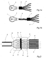
- Fig. 6 shows an example of how a light receiving end of an optical plug 40 with associated optical guides in the form of e.g. optical fibres may be constructed according to the invention.
- Light-receiving ends 41-45 and 41'-45' are thus fixed mutually with respect to the cross-section of the plug 40 so that they form the light-receiving end of the plug 40.
- the plug 40 shown may e.g. be for use in a car where one central light source illuminates the shown light-receiving ends via a lighting unit according to the invention.
- a product program with differently designed light receiving ends may be used with one and the same lighting unit 30, as the adaptation of the lighting unit to the optical cable may be performed software-wise by addressing other sets of microshutters which physically correspond to the plug used.
- Fig. 7 shows an example of such an application, where a plug of the type shown in fig. 6 is provided with four light-receiving ends of optical fibres 46, 46', 47 and 47'.
- optical guides may e.g. be intended to conduct light to a product type which has an additional lighting need relative to the product type that might correspond to the one shown in fig. 6.
- a lighting unit may be used as a standard unit in all product types, if only the physical/mechanical outer shape is maintained, since the adaptation of the lighting unit to the optical cable may take place software-wise, as mentioned above.
- some profiles in the allocation profile in a microshutter array corresponding to the one shown in fig. 5 are shown as dashed circles 51, 56 and 56', as precisely the number of selected microshutters within the circles 51, 56 and 56' together illuminate the corresponding fibre ends 41, 46 and 46'.
- These allocation circles may thus be subjected to a uniform or at least cooperating control in the form of e.g. intensity or colour control, as all microshutters within the shown circles 51, 56 and 56' are separately associated with precisely one fibre end. It should be stressed again that this allocation can take place software-wise, just as the microshutters outside the corresponding allocation circles will typically and advantageously be blocked completely.
- Each allocation profile 51, 56 and 56' is addressed e.g. by 20-200 microshutters which are subsequently subjected to a coordinated control algorithm, the purpose of which is e.g. that all microshutters in the allocation profile are opened or closed at the same time.
- one or more of the above-mentioned allocation profiles may e.g. be frequency-modulated, an alternative being to determine a strategy as to which light levels are desired at the lighting locaiton and which microshutters in the allocation profile are to be open or closed for these light levels.
- Fig. 8 is a perspective view of the structure of a plug corresponding to the plug shown in fig. 6.
- the shown plug 60 comprises a light-receiving end 61 and associated optical fibres 67, each of which has their light-receiving end 62 fixed in the plug 60.
- the mechanical structure of the plug may be provided suitably, depending on the necessary dimensioning and possible need for fixation of the plug in the corresponding lighting unit both in the longitudinal direction and the direction of rotation of the plug 60.
- the above-mentioned light control system may be used to advantage for the control of light in a car, it being possible to use one central light source optionally with a backup system for some of or all the lighting requirements that might exist in the car.
- Examples in addition to the externally mounted lights of the car include instrument panel lighting, interior lighting, contact lighting, etc.
- the invention partly enables simplified control of whether the light in the individual lighting devices actually works, partly simplifies the service considerably.
- the control of light in the car may thus be simplified and centralized at reduced costs.
- the invention may be put to many other uses.
- An example is displays where precisely one matrix of fibre ends can describe arbitrary combinations, e.g. characters, with one light source with electrical control, while the known principles require the use of separately arranged fibre ends for each desired character.
- the invention enables simple digital light control with a very great freedom in the adaptation of the individual light controls to the uses that might be desirable.
- An example of a subdivision might be a main unit that distributes light to the front and rear lights, parking lights, flashing indicators, etc. of the car, just as a single light guide, or an optical fibre, conducts light from the main unit to a subunit, which may e.g. be positioned in the vicinity of the instruments of the car, from which a subunit distributes light individually to the individual lights or positions at the instrument panel.
- This hierarchic subdivision e.g. enables automatic regulation of intensity and colour at the individual lighting locations as a function of background lighting, which may be provided in the main unit or the subunit according to the intended purpose.
- the subunit e.g. provides pixel lighting in e.g. a speedometer or other purely digitally constructed instruments, as each pixel in a display is controlled by a microshutter and associated light guide in the subunit.
- the light colour in the individual pixels may be changed by addressing a microshutter for the same light guide with another light filter.
- the invention is not just limited to e.g. lighting of cars, but is also contemplated for many other applications, such as e.g. traffic signs, where intensity and subject are digitally controlled, e.g. as a function of traffic, weather and the like.
Applications Claiming Priority (5)
| Application Number | Priority Date | Filing Date | Title |
|---|---|---|---|
| DK45396 | 1996-04-17 | ||
| DK45396 | 1996-04-17 | ||
| DK62896 | 1996-06-04 | ||
| DK62896 | 1996-06-04 | ||
| EP97919293A EP0894220B1 (de) | 1996-04-17 | 1997-04-17 | Verfahren und vorrichtung zur lichtkontrolle |
Related Parent Applications (1)
| Application Number | Title | Priority Date | Filing Date |
|---|---|---|---|
| EP97919293A Division EP0894220B1 (de) | 1996-04-17 | 1997-04-17 | Verfahren und vorrichtung zur lichtkontrolle |
Publications (3)
| Publication Number | Publication Date |
|---|---|
| EP1338846A2 true EP1338846A2 (de) | 2003-08-27 |
| EP1338846A3 EP1338846A3 (de) | 2004-03-03 |
| EP1338846B1 EP1338846B1 (de) | 2006-05-10 |
Family
ID=26064035
Family Applications (2)
| Application Number | Title | Priority Date | Filing Date |
|---|---|---|---|
| EP97919293A Expired - Lifetime EP0894220B1 (de) | 1996-04-17 | 1997-04-17 | Verfahren und vorrichtung zur lichtkontrolle |
| EP03012020A Expired - Lifetime EP1338846B1 (de) | 1996-04-17 | 1997-04-17 | Vorrichtung zur Lichtregelung |
Family Applications Before (1)
| Application Number | Title | Priority Date | Filing Date |
|---|---|---|---|
| EP97919293A Expired - Lifetime EP0894220B1 (de) | 1996-04-17 | 1997-04-17 | Verfahren und vorrichtung zur lichtkontrolle |
Country Status (9)
| Country | Link |
|---|---|
| US (1) | US6296383B1 (de) |
| EP (2) | EP0894220B1 (de) |
| JP (1) | JP4433335B2 (de) |
| CN (2) | CN1095057C (de) |
| AU (1) | AU2381797A (de) |
| BR (1) | BR9708687A (de) |
| DE (2) | DE69735860T2 (de) |
| ES (1) | ES2260545T3 (de) |
| WO (1) | WO1997039277A1 (de) |
Cited By (7)
| Publication number | Priority date | Publication date | Assignee | Title |
|---|---|---|---|---|
| US7636610B2 (en) | 2006-07-19 | 2009-12-22 | Envisiontec Gmbh | Method and device for producing a three-dimensional object, and computer and data carrier useful therefor |
| US8126580B2 (en) | 2006-04-26 | 2012-02-28 | Envisiontec Gmbh | Device and method for producing a three-dimensional object by means of mask exposure |
| US8658076B2 (en) | 2007-10-26 | 2014-02-25 | Envisiontec Gmbh | Process and freeform fabrication system for producing a three-dimensional object |
| EP2876470A1 (de) * | 2013-11-20 | 2015-05-27 | Christie Digital Systems Canada, Inc. | Vorrichtung zur gleichmäßigen Verteilung von Licht |
| US9067361B2 (en) | 2007-07-04 | 2015-06-30 | Envisiontec Gmbh | Process and device for producing a three-dimensional object |
| US9527244B2 (en) | 2014-02-10 | 2016-12-27 | Global Filtration Systems | Apparatus and method for forming three-dimensional objects from solidifiable paste |
| US10737479B2 (en) | 2017-01-12 | 2020-08-11 | Global Filtration Systems | Method of making three-dimensional objects using both continuous and discontinuous solidification |
Families Citing this family (62)
| Publication number | Priority date | Publication date | Assignee | Title |
|---|---|---|---|---|
| US6188933B1 (en) * | 1997-05-12 | 2001-02-13 | Light & Sound Design Ltd. | Electronically controlled stage lighting system |
| AU6188399A (en) * | 1998-10-12 | 2000-05-01 | Dicon A/S | Rapid prototyping apparatus and method of rapid prototyping |
| US6614972B1 (en) * | 1998-12-02 | 2003-09-02 | 3M Innovative Properties Company | Coupler for transporting and distributing light to multiple locations with uniform color and intensity |
| US6618530B1 (en) | 1998-12-02 | 2003-09-09 | 3M Innovative Properties Company | Apparatus for transporting and distributing light using multiple light fibers |
| US6718115B1 (en) * | 2000-09-29 | 2004-04-06 | Palmone, Inc. | Personal digital assistant display illumination method and system |
| US6666563B2 (en) | 2002-04-12 | 2003-12-23 | Dahvid N. Brown | Illumination device |
| US7015458B2 (en) * | 2002-10-10 | 2006-03-21 | Emerging Manufacturing Technology, Inc. | High density fiber optic output interface and system |
| US7417782B2 (en) | 2005-02-23 | 2008-08-26 | Pixtronix, Incorporated | Methods and apparatus for spatial light modulation |
| DE10320520A1 (de) * | 2003-04-30 | 2004-11-18 | Carl Zeiss Smt Ag | Beleuchtungssystem mit Diffusorelement |
| DE10325330B4 (de) * | 2003-06-04 | 2010-06-02 | Automotive Lighting Reutlingen Gmbh | Scheinwerfer für Kraftfahrzeuge |
| DE102004022606A1 (de) | 2004-05-07 | 2005-12-15 | Envisiontec Gmbh | Verfahren zur Herstellung eines dreidimensionalen Objekts mit verbesserter Trennung ausgehärteter Materialschichten von einer Bauebene |
| TWI257018B (en) * | 2004-07-07 | 2006-06-21 | Epistar Corp | A back light module with independent light source |
| CN100594394C (zh) * | 2004-10-28 | 2010-03-17 | 诺瓦提斯公司 | 用于传输短弧灯发射的光的设备 |
| US7271945B2 (en) * | 2005-02-23 | 2007-09-18 | Pixtronix, Inc. | Methods and apparatus for actuating displays |
| US7616368B2 (en) | 2005-02-23 | 2009-11-10 | Pixtronix, Inc. | Light concentrating reflective display methods and apparatus |
| US8519945B2 (en) | 2006-01-06 | 2013-08-27 | Pixtronix, Inc. | Circuits for controlling display apparatus |
| US9261694B2 (en) | 2005-02-23 | 2016-02-16 | Pixtronix, Inc. | Display apparatus and methods for manufacture thereof |
| US9082353B2 (en) | 2010-01-05 | 2015-07-14 | Pixtronix, Inc. | Circuits for controlling display apparatus |
| US8159428B2 (en) | 2005-02-23 | 2012-04-17 | Pixtronix, Inc. | Display methods and apparatus |
| US7742016B2 (en) | 2005-02-23 | 2010-06-22 | Pixtronix, Incorporated | Display methods and apparatus |
| US7746529B2 (en) | 2005-02-23 | 2010-06-29 | Pixtronix, Inc. | MEMS display apparatus |
| US9229222B2 (en) | 2005-02-23 | 2016-01-05 | Pixtronix, Inc. | Alignment methods in fluid-filled MEMS displays |
| US7755582B2 (en) | 2005-02-23 | 2010-07-13 | Pixtronix, Incorporated | Display methods and apparatus |
| US7304786B2 (en) | 2005-02-23 | 2007-12-04 | Pixtronix, Inc. | Methods and apparatus for bi-stable actuation of displays |
| US8310442B2 (en) | 2005-02-23 | 2012-11-13 | Pixtronix, Inc. | Circuits for controlling display apparatus |
| US7304785B2 (en) * | 2005-02-23 | 2007-12-04 | Pixtronix, Inc. | Display methods and apparatus |
| US7999994B2 (en) | 2005-02-23 | 2011-08-16 | Pixtronix, Inc. | Display apparatus and methods for manufacture thereof |
| US8482496B2 (en) | 2006-01-06 | 2013-07-09 | Pixtronix, Inc. | Circuits for controlling MEMS display apparatus on a transparent substrate |
| US9158106B2 (en) | 2005-02-23 | 2015-10-13 | Pixtronix, Inc. | Display methods and apparatus |
| US20070205969A1 (en) | 2005-02-23 | 2007-09-06 | Pixtronix, Incorporated | Direct-view MEMS display devices and methods for generating images thereon |
| US7675665B2 (en) | 2005-02-23 | 2010-03-09 | Pixtronix, Incorporated | Methods and apparatus for actuating displays |
| US7502159B2 (en) | 2005-02-23 | 2009-03-10 | Pixtronix, Inc. | Methods and apparatus for actuating displays |
| US8526096B2 (en) | 2006-02-23 | 2013-09-03 | Pixtronix, Inc. | Mechanical light modulators with stressed beams |
| DE102006019964C5 (de) | 2006-04-28 | 2021-08-26 | Envisiontec Gmbh | Vorrichtung und Verfahren zur Herstellung eines dreidimensionalen Objekts mittels Maskenbelichtung |
| US7876489B2 (en) | 2006-06-05 | 2011-01-25 | Pixtronix, Inc. | Display apparatus with optical cavities |
| WO2008051362A1 (en) | 2006-10-20 | 2008-05-02 | Pixtronix, Inc. | Light guides and backlight systems incorporating light redirectors at varying densities |
| US7892474B2 (en) | 2006-11-15 | 2011-02-22 | Envisiontec Gmbh | Continuous generative process for producing a three-dimensional object |
| US8003039B2 (en) | 2007-01-17 | 2011-08-23 | 3D Systems, Inc. | Method for tilting solid image build platform for reducing air entrainment and for build release |
| US9176318B2 (en) | 2007-05-18 | 2015-11-03 | Pixtronix, Inc. | Methods for manufacturing fluid-filled MEMS displays |
| US7852546B2 (en) | 2007-10-19 | 2010-12-14 | Pixtronix, Inc. | Spacers for maintaining display apparatus alignment |
| US8248560B2 (en) | 2008-04-18 | 2012-08-21 | Pixtronix, Inc. | Light guides and backlight systems incorporating prismatic structures and light redirectors |
| US8169679B2 (en) | 2008-10-27 | 2012-05-01 | Pixtronix, Inc. | MEMS anchors |
| US8194178B2 (en) * | 2008-12-19 | 2012-06-05 | Omnivision Technologies, Inc. | Programmable micro-electromechanical microshutter array |
| KR101055372B1 (ko) * | 2009-07-29 | 2011-08-08 | 김혁중 | 멀티광케이블을 통한 led 집광장치 |
| GB2474460A (en) * | 2009-10-14 | 2011-04-20 | Sharp Kk | Lighting system for selectively coupling a light source to light outputs |
| US8372330B2 (en) | 2009-10-19 | 2013-02-12 | Global Filtration Systems | Resin solidification substrate and assembly |
| KR20120132680A (ko) | 2010-02-02 | 2012-12-07 | 픽스트로닉스 인코포레이티드 | 저온 실 유체 충전된 디스플레이 장치의 제조 방법 |
| BR112012019383A2 (pt) | 2010-02-02 | 2017-09-12 | Pixtronix Inc | Circuitos para controlar aparelho de exibição |
| US9658379B2 (en) | 2010-12-15 | 2017-05-23 | Thomas Mark Spangler | Fiber optic display apparatus and methods of osillating illuminated optical fibers |
| CN103158604A (zh) * | 2011-12-13 | 2013-06-19 | 苏州洲通光电科技有限公司 | 一种车辆内部灯光系统 |
| US9134552B2 (en) | 2013-03-13 | 2015-09-15 | Pixtronix, Inc. | Display apparatus with narrow gap electrostatic actuators |
| AT514967B1 (de) * | 2013-10-25 | 2015-08-15 | Zizala Lichtsysteme Gmbh | Mikroprojektions-Lichtmodul für einen Kraftfahrzeugscheinwerfer |
| DE102014115068A1 (de) * | 2014-10-16 | 2016-04-21 | Osram Opto Semiconductors Gmbh | Beleuchtungsanordnung |
| CN105805577B (zh) * | 2016-05-07 | 2019-04-02 | 浙江大学 | 对被照面进行可控间歇均匀照明的照明系统 |
| CN109239971A (zh) * | 2018-11-14 | 2019-01-18 | 济南维康安防电子有限公司 | 一种无色差液晶显示装置 |
| US11239637B2 (en) | 2018-12-21 | 2022-02-01 | Kyocera Sld Laser, Inc. | Fiber delivered laser induced white light system |
| US11421843B2 (en) | 2018-12-21 | 2022-08-23 | Kyocera Sld Laser, Inc. | Fiber-delivered laser-induced dynamic light system |
| US11884202B2 (en) | 2019-01-18 | 2024-01-30 | Kyocera Sld Laser, Inc. | Laser-based fiber-coupled white light system |
| DE102020002323B3 (de) | 2020-04-07 | 2021-07-22 | Sioptica Gmbh | Optisches Element zur Beeinflussung von Lichtrichtungen und Bildschirm mit einem solchen optischen Element |
| CN116068776A (zh) * | 2021-10-29 | 2023-05-05 | 华为技术有限公司 | 一种分光方法以及相关设备 |
| CN114299822A (zh) * | 2021-11-24 | 2022-04-08 | 石家庄市京华电子实业有限公司 | 一种基于大功率led的微小间距led显示屏模组 |
| DE102022207724A1 (de) * | 2022-07-27 | 2024-02-01 | UNO MINDA Europe GmbH | Beleuchtungsmodul |
Citations (1)
| Publication number | Priority date | Publication date | Assignee | Title |
|---|---|---|---|---|
| US5434756A (en) | 1992-10-29 | 1995-07-18 | Hughes Aircraft Company | Distributed lighting system with fiber optic controls |
Family Cites Families (21)
| Publication number | Priority date | Publication date | Assignee | Title |
|---|---|---|---|---|
| US3564231A (en) | 1968-09-26 | 1971-02-16 | Poly Optics | Illumination device |
| US4015122A (en) * | 1974-07-12 | 1977-03-29 | Rubinstein Walter M | Photo-electric object detection system |
| US4349259A (en) * | 1981-09-08 | 1982-09-14 | Eastman Kodak Company | Exposure control mechanism for use with chemical flash |
| US4531197A (en) * | 1983-04-27 | 1985-07-23 | The United States Of America As Represented By The Secretary Of The Navy | Real-time Fourier transformer using one acousto-optical cell |
| US4860172A (en) * | 1988-01-19 | 1989-08-22 | Biotronics Associates, Inc. | Lamp-based laser simulator |
| US4907132A (en) * | 1988-03-22 | 1990-03-06 | Lumitex, Inc. | Light emitting panel assemblies and method of making same |
| US5042900A (en) * | 1988-09-12 | 1991-08-27 | Lumitex, Inc. | Connector assemblies for optical fiber light cables |
| JPH02158002A (ja) * | 1988-12-12 | 1990-06-18 | Hazama Gumi Ltd | 演出照明装置 |
| US5102227A (en) * | 1989-12-01 | 1992-04-07 | Dolan-Jenner | Lighting and detection system |
| JP2546377Y2 (ja) * | 1991-02-27 | 1997-08-27 | 株式会社小糸製作所 | 車輌用照明灯 |
| FI89834C (fi) * | 1991-06-03 | 1993-11-25 | Teatteritekniikan Kehittaemisk | Straolkastare foer belysning av miniatyrmodell i skala |
| JP2588317Y2 (ja) * | 1992-04-01 | 1999-01-06 | 東陶機器株式会社 | 照明装置 |
| US5184883A (en) * | 1992-05-01 | 1993-02-09 | General Electric Company | Automobile lighting system that includes an exterior indicating device |
| US5226709A (en) * | 1992-07-22 | 1993-07-13 | Labranche Gerard A | Lighting arrangement for Christmas trees |
| JP2555922B2 (ja) * | 1993-02-26 | 1996-11-20 | 日本電気株式会社 | 静電駆動マイクロシャッターおよびシャッターアレイ |
| JPH0712678A (ja) * | 1993-06-28 | 1995-01-17 | Nec Corp | 受光素子特性検査装置 |
| US5475571A (en) * | 1994-03-30 | 1995-12-12 | Ford Motor Company | Ring Light collector |
| FR2726135B1 (fr) * | 1994-10-25 | 1997-01-17 | Suisse Electronique Microtech | Dispositif de commutation |
| JPH08138407A (ja) * | 1994-11-09 | 1996-05-31 | Nippondenso Co Ltd | 照明装置 |
| JP3012953U (ja) * | 1994-12-26 | 1995-06-27 | 株式会社ケンコー | 照明装置 |
| JP3799092B2 (ja) * | 1995-12-29 | 2006-07-19 | アジレント・テクノロジーズ・インク | 光変調装置及びディスプレイ装置 |
-
1997
- 1997-04-17 EP EP97919293A patent/EP0894220B1/de not_active Expired - Lifetime
- 1997-04-17 JP JP53666597A patent/JP4433335B2/ja not_active Expired - Lifetime
- 1997-04-17 AU AU23817/97A patent/AU2381797A/en not_active Abandoned
- 1997-04-17 DE DE69735860T patent/DE69735860T2/de not_active Expired - Lifetime
- 1997-04-17 DE DE69725124T patent/DE69725124T2/de not_active Expired - Lifetime
- 1997-04-17 ES ES03012020T patent/ES2260545T3/es not_active Expired - Lifetime
- 1997-04-17 BR BR9708687-8A patent/BR9708687A/pt not_active IP Right Cessation
- 1997-04-17 WO PCT/DK1997/000171 patent/WO1997039277A1/en active IP Right Grant
- 1997-04-17 CN CN97193889A patent/CN1095057C/zh not_active Expired - Fee Related
- 1997-04-17 EP EP03012020A patent/EP1338846B1/de not_active Expired - Lifetime
- 1997-04-17 US US09/171,391 patent/US6296383B1/en not_active Expired - Lifetime
-
2002
- 2002-04-29 CN CN02119046A patent/CN1441192A/zh active Pending
Patent Citations (1)
| Publication number | Priority date | Publication date | Assignee | Title |
|---|---|---|---|---|
| US5434756A (en) | 1992-10-29 | 1995-07-18 | Hughes Aircraft Company | Distributed lighting system with fiber optic controls |
Cited By (12)
| Publication number | Priority date | Publication date | Assignee | Title |
|---|---|---|---|---|
| US8126580B2 (en) | 2006-04-26 | 2012-02-28 | Envisiontec Gmbh | Device and method for producing a three-dimensional object by means of mask exposure |
| DE102006019963B4 (de) | 2006-04-28 | 2023-12-07 | Envisiontec Gmbh | Vorrichtung und Verfahren zur Herstellung eines dreidimensionalen Objekts durch schichtweises Verfestigen eines unter Einwirkung von elektromagnetischer Strahlung verfestigbaren Materials mittels Maskenbelichtung |
| US7636610B2 (en) | 2006-07-19 | 2009-12-22 | Envisiontec Gmbh | Method and device for producing a three-dimensional object, and computer and data carrier useful therefor |
| US9067361B2 (en) | 2007-07-04 | 2015-06-30 | Envisiontec Gmbh | Process and device for producing a three-dimensional object |
| US10220565B2 (en) | 2007-07-04 | 2019-03-05 | Envisiontec Gmbh | Process and device for producing a three-dimensional object |
| US8658076B2 (en) | 2007-10-26 | 2014-02-25 | Envisiontec Gmbh | Process and freeform fabrication system for producing a three-dimensional object |
| EP2876470A1 (de) * | 2013-11-20 | 2015-05-27 | Christie Digital Systems Canada, Inc. | Vorrichtung zur gleichmäßigen Verteilung von Licht |
| US9335612B2 (en) | 2013-11-20 | 2016-05-10 | Christie Digital Systems Usa, Inc. | System for uniform distribution of light using an array of lenslets |
| US9527244B2 (en) | 2014-02-10 | 2016-12-27 | Global Filtration Systems | Apparatus and method for forming three-dimensional objects from solidifiable paste |
| US9975296B2 (en) | 2014-02-10 | 2018-05-22 | Global Filtration Systems | Apparatus and method for forming three-dimensional objects from solidifiable paste |
| US10737479B2 (en) | 2017-01-12 | 2020-08-11 | Global Filtration Systems | Method of making three-dimensional objects using both continuous and discontinuous solidification |
| US11413856B2 (en) | 2017-01-12 | 2022-08-16 | Global Filtration Systems | Method of making three-dimensional objects using both continuous and discontinuous solidification |
Also Published As
| Publication number | Publication date |
|---|---|
| DE69725124D1 (de) | 2003-10-30 |
| EP1338846A3 (de) | 2004-03-03 |
| EP1338846B1 (de) | 2006-05-10 |
| BR9708687A (pt) | 2000-01-04 |
| EP0894220B1 (de) | 2003-09-24 |
| AU2381797A (en) | 1997-11-07 |
| US6296383B1 (en) | 2001-10-02 |
| EP0894220A1 (de) | 1999-02-03 |
| CN1216605A (zh) | 1999-05-12 |
| CN1095057C (zh) | 2002-11-27 |
| DE69735860D1 (de) | 2006-06-14 |
| DE69725124T2 (de) | 2004-06-09 |
| WO1997039277A1 (en) | 1997-10-23 |
| JP4433335B2 (ja) | 2010-03-17 |
| DE69735860T2 (de) | 2006-12-28 |
| CN1441192A (zh) | 2003-09-10 |
| JP2000508821A (ja) | 2000-07-11 |
| ES2260545T3 (es) | 2006-11-01 |
Similar Documents
| Publication | Publication Date | Title |
|---|---|---|
| US6296383B1 (en) | Method and apparatus for controlling light | |
| US7693368B2 (en) | Three color digital gobo system | |
| US6152588A (en) | Addressable vehicular lighting system | |
| US6995355B2 (en) | Optical integrating chamber lighting using multiple color sources | |
| US6846082B2 (en) | Rear-projecting device | |
| US20070241340A1 (en) | Micro-mirror based display device having an improved light source | |
| US20120212707A1 (en) | Multi-Segment Imager | |
| US20090296408A1 (en) | Light distribution | |
| EP0807032B1 (de) | Verfahren und einrichtung zum senden von warnungsfarblicht | |
| US5873645A (en) | Fiber optic cellular reflector | |
| US5691696A (en) | System and method for broadcasting colored light for emergency signals | |
| KR100466671B1 (ko) | 광을제어하는방법및그장치 | |
| US6007226A (en) | Fiber optic light | |
| US4420740A (en) | Obstruction warning system | |
| CA2251730C (en) | Method and apparatus for controlling light | |
| US5909525A (en) | Electro-optical relay | |
| US5563588A (en) | Fiber optic traffic signal light system having a shutter control | |
| US5147128A (en) | Fiberoptic multi-beam roadway illumination device | |
| GB2342466A (en) | Light projector | |
| CN216249941U (zh) | 投影灯具模块、投影系统及车辆 | |
| US20200240609A1 (en) | Vehicle lighting device with a digital micromirror device | |
| JPH0577811U (ja) | 光ファイバ照明装置 | |
| CN114423992A (zh) | 具有机动化准直控制的照明装置 |
Legal Events
| Date | Code | Title | Description |
|---|---|---|---|
| PUAI | Public reference made under article 153(3) epc to a published international application that has entered the european phase |
Free format text: ORIGINAL CODE: 0009012 |
|
| AC | Divisional application: reference to earlier application |
Ref document number: 0894220 Country of ref document: EP Kind code of ref document: P |
|
| AK | Designated contracting states |
Designated state(s): DE ES FR GB IT |
|
| PUAL | Search report despatched |
Free format text: ORIGINAL CODE: 0009013 |
|
| AK | Designated contracting states |
Kind code of ref document: A3 Designated state(s): DE ES FR GB IT |
|
| 17P | Request for examination filed |
Effective date: 20040823 |
|
| AKX | Designation fees paid |
Designated state(s): DE ES FR GB IT |
|
| 17Q | First examination report despatched |
Effective date: 20041223 |
|
| GRAP | Despatch of communication of intention to grant a patent |
Free format text: ORIGINAL CODE: EPIDOSNIGR1 |
|
| RTI1 | Title (correction) |
Free format text: APPARATUS FOR CONTROLLING LIGHT |
|
| GRAS | Grant fee paid |
Free format text: ORIGINAL CODE: EPIDOSNIGR3 |
|
| GRAA | (expected) grant |
Free format text: ORIGINAL CODE: 0009210 |
|
| RAP1 | Party data changed (applicant data changed or rights of an application transferred) |
Owner name: HUNTSMAN ADVANCED MATERIALS (SWITZERLAND) GMBH |
|
| AC | Divisional application: reference to earlier application |
Ref document number: 0894220 Country of ref document: EP Kind code of ref document: P |
|
| AK | Designated contracting states |
Kind code of ref document: B1 Designated state(s): DE ES FR GB IT |
|
| PG25 | Lapsed in a contracting state [announced via postgrant information from national office to epo] |
Ref country code: IT Free format text: LAPSE BECAUSE OF FAILURE TO SUBMIT A TRANSLATION OF THE DESCRIPTION OR TO PAY THE FEE WITHIN THE PRESCRIBED TIME-LIMIT;WARNING: LAPSES OF ITALIAN PATENTS WITH EFFECTIVE DATE BEFORE 2007 MAY HAVE OCCURRED AT ANY TIME BEFORE 2007. THE CORRECT EFFECTIVE DATE MAY BE DIFFERENT FROM THE ONE RECORDED. Effective date: 20060510 |
|
| REG | Reference to a national code |
Ref country code: GB Ref legal event code: FG4D |
|
| REF | Corresponds to: |
Ref document number: 69735860 Country of ref document: DE Date of ref document: 20060614 Kind code of ref document: P |
|
| REG | Reference to a national code |
Ref country code: ES Ref legal event code: FG2A Ref document number: 2260545 Country of ref document: ES Kind code of ref document: T3 |
|
| ET | Fr: translation filed | ||
| PLBE | No opposition filed within time limit |
Free format text: ORIGINAL CODE: 0009261 |
|
| STAA | Information on the status of an ep patent application or granted ep patent |
Free format text: STATUS: NO OPPOSITION FILED WITHIN TIME LIMIT |
|
| 26N | No opposition filed |
Effective date: 20070213 |
|
| PGFP | Annual fee paid to national office [announced via postgrant information from national office to epo] |
Ref country code: ES Payment date: 20110425 Year of fee payment: 15 |
|
| REG | Reference to a national code |
Ref country code: DE Ref legal event code: R082 Ref document number: 69735860 Country of ref document: DE Representative=s name: VON KREISLER SELTING WERNER, DE |
|
| REG | Reference to a national code |
Ref country code: GB Ref legal event code: 732E Free format text: REGISTERED BETWEEN 20120712 AND 20120718 |
|
| REG | Reference to a national code |
Ref country code: FR Ref legal event code: TP Owner name: 3D SYSTEMS, INC., US Effective date: 20120730 |
|
| REG | Reference to a national code |
Ref country code: DE Ref legal event code: R081 Ref document number: 69735860 Country of ref document: DE Owner name: 3D SYSTEMS, INC., US Free format text: FORMER OWNER: HUNTSMAN ADVANCED MATERIALS (SWITZERLAND) GMBH, BASEL, CH Effective date: 20120730 Ref country code: DE Ref legal event code: R082 Ref document number: 69735860 Country of ref document: DE Representative=s name: VON KREISLER SELTING WERNER, DE Effective date: 20120730 Ref country code: DE Ref legal event code: R082 Ref document number: 69735860 Country of ref document: DE Representative=s name: VON KREISLER SELTING WERNER - PARTNERSCHAFT VO, DE Effective date: 20120730 Ref country code: DE Ref legal event code: R081 Ref document number: 69735860 Country of ref document: DE Owner name: 3D SYSTEMS, INC., ROCK HILL, US Free format text: FORMER OWNER: HUNTSMAN ADVANCED MATERIALS (SWITZERLAND) GMBH, BASEL, CH Effective date: 20120730 Ref country code: DE Ref legal event code: R082 Ref document number: 69735860 Country of ref document: DE Representative=s name: DOMPATENT VON KREISLER SELTING WERNER - PARTNE, DE Effective date: 20120730 |
|
| REG | Reference to a national code |
Ref country code: ES Ref legal event code: FD2A Effective date: 20130715 |
|
| PG25 | Lapsed in a contracting state [announced via postgrant information from national office to epo] |
Ref country code: ES Free format text: LAPSE BECAUSE OF NON-PAYMENT OF DUE FEES Effective date: 20120418 |
|
| REG | Reference to a national code |
Ref country code: FR Ref legal event code: PLFP Year of fee payment: 19 |
|
| PGFP | Annual fee paid to national office [announced via postgrant information from national office to epo] |
Ref country code: DE Payment date: 20150429 Year of fee payment: 19 Ref country code: GB Payment date: 20150427 Year of fee payment: 19 |
|
| PGFP | Annual fee paid to national office [announced via postgrant information from national office to epo] |
Ref country code: IT Payment date: 20150428 Year of fee payment: 19 Ref country code: FR Payment date: 20150417 Year of fee payment: 19 |
|
| REG | Reference to a national code |
Ref country code: DE Ref legal event code: R119 Ref document number: 69735860 Country of ref document: DE |
|
| GBPC | Gb: european patent ceased through non-payment of renewal fee |
Effective date: 20160417 |
|
| REG | Reference to a national code |
Ref country code: FR Ref legal event code: ST Effective date: 20161230 |
|
| PG25 | Lapsed in a contracting state [announced via postgrant information from national office to epo] |
Ref country code: GB Free format text: LAPSE BECAUSE OF NON-PAYMENT OF DUE FEES Effective date: 20160417 Ref country code: DE Free format text: LAPSE BECAUSE OF NON-PAYMENT OF DUE FEES Effective date: 20161101 Ref country code: FR Free format text: LAPSE BECAUSE OF NON-PAYMENT OF DUE FEES Effective date: 20160502 |
|
| PG25 | Lapsed in a contracting state [announced via postgrant information from national office to epo] |
Ref country code: IT Free format text: LAPSE BECAUSE OF NON-PAYMENT OF DUE FEES Effective date: 20160417 |