EP1337049A2 - Funkbasisstation - Google Patents
Funkbasisstation Download PDFInfo
- Publication number
- EP1337049A2 EP1337049A2 EP03002507A EP03002507A EP1337049A2 EP 1337049 A2 EP1337049 A2 EP 1337049A2 EP 03002507 A EP03002507 A EP 03002507A EP 03002507 A EP03002507 A EP 03002507A EP 1337049 A2 EP1337049 A2 EP 1337049A2
- Authority
- EP
- European Patent Office
- Prior art keywords
- signal
- base station
- amplifier
- gain
- mast head
- Prior art date
- Legal status (The legal status is an assumption and is not a legal conclusion. Google has not performed a legal analysis and makes no representation as to the accuracy of the status listed.)
- Withdrawn
Links
Images


Classifications
-
- H—ELECTRICITY
- H03—ELECTRONIC CIRCUITRY
- H03G—CONTROL OF AMPLIFICATION
- H03G1/00—Details of arrangements for controlling amplification
- H03G1/0005—Circuits characterised by the type of controlling devices operated by a controlling current or voltage signal
- H03G1/0017—Circuits characterised by the type of controlling devices operated by a controlling current or voltage signal the device being at least one of the amplifying solid state elements of the amplifier
- H03G1/0023—Circuits characterised by the type of controlling devices operated by a controlling current or voltage signal the device being at least one of the amplifying solid state elements of the amplifier in emitter-coupled or cascode amplifiers
-
- H—ELECTRICITY
- H04—ELECTRIC COMMUNICATION TECHNIQUE
- H04B—TRANSMISSION
- H04B1/00—Details of transmission systems, not covered by a single one of groups H04B3/00 - H04B13/00; Details of transmission systems not characterised by the medium used for transmission
- H04B1/06—Receivers
- H04B1/16—Circuits
- H04B1/18—Input circuits, e.g. for coupling to an antenna or a transmission line
-
- H—ELECTRICITY
- H04—ELECTRIC COMMUNICATION TECHNIQUE
- H04B—TRANSMISSION
- H04B1/00—Details of transmission systems, not covered by a single one of groups H04B3/00 - H04B13/00; Details of transmission systems not characterised by the medium used for transmission
- H04B1/38—Transceivers, i.e. devices in which transmitter and receiver form a structural unit and in which at least one part is used for functions of transmitting and receiving
- H04B1/40—Circuits
- H04B1/44—Transmit/receive switching
- H04B1/48—Transmit/receive switching in circuits for connecting transmitter and receiver to a common transmission path, e.g. by energy of transmitter
Definitions
- the present invention relates to a radio base station. More specifically, the present invention relates to a radio base station which can precisely set the gain of an input signal.
- JP-U- 62-75653 A technique related to an automatic transmission cable loss compensating system is described in JP-U- 62-75653.
- an automatic transmission cable loss compensating system is provided with means for discriminating cable length at at least one terminal of a connector provided at the reception side end of a transmission cable having a plurality of signal transmission lines bound therein. It is provided with a gain control amplifier for compensating for the transmission loss of an input signal in a receiver. When the connector is coupled to the receiver, the gain of the gain control amplifier corresponding to the cable length is controlled to automatically compensate for the transmission cable loss.
- a transmitter amplifies or frequency converts an input signal for transmission.
- a transmitting power controller is provided with a comparator and a hold circuit.
- the comparator configures an ALC loop by an input level detector detecting the level of the input signal, an output level detector detecting the level of a transmitted output signal, and means controlling the gain of the transmitter based on a detected value of each of the level detectors, and compares the input level with a reference value.
- the hold circuit brings the operation of the ALC loop into a fixed state.
- the hold circuit is driven to fix the gain of the ALC loop by a value immediately before it.
- a transmitter transmits a signal via a transmission cable to a receiver.
- the transmitter side has high frequency oscillation means oscillating a high frequency signal in a predetermined period, high frequency superimposition means superimposing the high frequency signal oscillated by the high frequency oscillation means on a transmission signal, and a first switch connected between the high frequency oscillation means and the high frequency superimposition means.
- the receiver side has high frequency detection means detecting the high frequency signal transmitted from the transmitter side via the transmission cable, and cable length discrimination means discriminating cable length by the detected output level obtained from the high frequency detection means.
- the receiver side also has gain control means controlling the gain of the transmitted signal based on the discriminated output by the cable length discrimination means, and a second switch connected between the high frequency detection means and the gain control means.
- JP-A- 11-205056 A technique related to a receiver is described in JP-A- 11-205056.
- a receiver has a receiving antenna receiving an incoming communication electric wave to obtain a received signal, and a receiver body decoding the received signal to obtain a decoded signal.
- the receiver also has a coaxial cable connecting the receiving antenna and the receiver body and transmitting the received signal between the receiving antenna and the receiver body, and an amplifier amplifying the level of the received signal to compensate for the transmission loss of the coaxial cable.
- the receiver body has variable attenuation means adjusting the level of the received signal transmitted from the coaxial cable to the receiver body.
- the receiver body also has control means controlling the variable attenuation means so that the total of the gain of the amplifier, the gain of the coaxial cable and the gain of the variable attenuation means is a predetermined value by the variable attenuation means.
- a base station of a radio system has a base station device including at least one transmitter unit.
- the base station of a radio system has antenna means for receiving a signal given by the transmitter unit which may be away from the base station device and is connected to the transmitter unit of the base station device by at least one cable.
- the antenna means has amplification means for amplifying the signal received from the transmitter unit via the cable and means for transmitting the amplified signal to a receiver unit in the radio coverage area of the base station.
- the amplification means has a variable gain amplifier, a first sampling means for sampling a signal given to the input of the amplifier via the cable, and a second sampling means for sampling the signal transmitted from the amplifier to an antenna.
- the amplification means has adjusting means for adjusting the gain of the amplifier to obtain a fixed gain in response to the first and second sampling means.
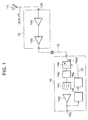
- the prior art radio base station 10j has an antenna 11j, a mast head amplifier 12j, a base station receiver 14j, and a feeder (coaxial cable) 13j connecting the mast head amplifier 12j and the base station receiver 14j.
- the mast head amplifier 12j is installed to increase the effective sensitivity of an induced signal 15 in the base station receiver 14j and has a first first-stage amplifier 12aj, an amplifier 12dj, and an input terminal 12fj.
- the base station receiver 14j has a variable attenuator 14aj, a frequency converter 14bj, an intermediate frequency filter 14cj, an intermediate frequency amplifier 14dj, an output terminal 14ej, a detector 14fj, and a controller 14gj.
- the first first-stage amplifier 12aj is connected to the antenna 11j via the input terminal 12fj and inputted the induced signal 15 from the antenna 11j.
- the amplifier 12dj amplifies the induced signal 15 inputted from the first first-stage amplifier 12aj, and outputs it to the variable attenuator 14aj.
- the induced signal 15 corresponds to a power induced by an electric wave received by the antenna 11j.
- the variable attenuator 14aj adjusts the induced signal 15 outputted from the amplifier 12dj.
- the frequency converter 14bj converts the frequency of the induced signal 15 outputted from the variable attenuator 14aj.
- the intermediate frequency filter 14cj removes unnecessary frequencies from the induced signals 15 which is frequency-converted by the frequency converter 14bj.
- the intermediate frequency amplifier 14dj amplifies the induced signal 15 via the intermediate frequency filter 14cj.
- the induced signal which is amplified by the intermediate frequency amplifier 14dj is outputted to the output terminal 14ej.
- the detector 14fj detects an output power 18 (outputted from the intermediate frequency amplifier 14dj) at the output terminal 14ej to output the detected result to the controller 14gj.
- the controller 14gj When inputting the output power 18 from the detector 14fj, the controller 14gj outputs a power notification signal 33 including information showing the output power 18 to the variable attenuator 14aj to control the variable attenuator 14aj. By said control, the output power 18 at the output terminal 14ej is adjusted to a predetermined value.
- the radio base station 10j must precisely set a received gain to optimize thermal noise and distortion noise for preciselymeasure of a reception level.
- the amplification degree (or gain) of the induced signal 15 is not always fixed via the mast head amplifier 12j and the base station receiver 14j. This is caused mainly by variation in gain of the mast head amplifier 12j and variation in transmission loss (attenuation) due to the length, type and maintenance conditions of the feeder 13j.
- the method has the following problems:
- An object of the present invention is to provide a radio base station which can automatically correct variation in gain of a mast head amplifier.
- Another object of the present invention is to provide a system which can automatically correct variation in transmission loss due to the length, type and maintenance conditions of a feeder.
- a further object of the present invention is to provide a radio base station which can minimize an error of the gain of a received signal.
- a radio base station (10) of the present invention has a terminating set (12e) and an antenna (11), and includes a mast head amplifier (12) amplifying and outputting any one signal (22) of a first signal (21) inputted from the terminating set (12e) and a second signal (15) inputted from the antenna (11).
- the radio base station (10) of the present invention also includes a base station receiver (14) connected to the mast head amplifier (12) adjusting an intensity (24) of the first signal (21) so that the intensity (24) of the first signal (21) is a predetermined value (25) to set a first gain (30) of the first signal (21) when inputting the first signal (21) from the mast head amplifier (12), and adjusting an intensity (19) of the second signal (15) based on the set first gain (30) when inputting the second signal (15) from the mast head amplifier (12).
- a base station receiver (14) connected to the mast head amplifier (12) adjusting an intensity (24) of the first signal (21) so that the intensity (24) of the first signal (21) is a predetermined value (25) to set a first gain (30) of the first signal (21) when inputting the first signal (21) from the mast head amplifier (12), and adjusting an intensity (19) of the second signal (15) based on the set first gain (30) when inputting the second signal (15) from the mast head amplifier (12).
- the radio base station (10) of the present invention further includes a feeder (13) connecting the mast head amplifier (12) and the base station receiver (14) and transmitting the first signal (21) to output it to the base station receiver (14) when inputting the first signal (21) from the mast head amplifier (12).
- the base station receiver (14) adjusts the intensity (24) of the first signal (21) inputted fromthe feeder (13) based on the predetermined value (25) and an attenuation (27) when the first signal (21) is transmitted via the feeder (13).
- the feeder (13) transmits the second signal (15) to output it to the base station receiver (14) when inputting the second signal (15) from the mast head amplifier (12).
- the base station receiver (14) adjusts the intensity (19) of the second signal (15) inputted from the feeder (13) based on the set first gain (30).
- the mast head amplifier (12) includes a first first-stage amplifier (12a) connected to the terminating set (12e) amplifying and outputting the first signal (21) inputted from the terminating set (12e) and a second first-stage amplifier (12b) connected to the antenna (11) amplifying and outputting the second signal (15) inputted from the antenna (11).
- the mast head amplifier (12) also includes a switch (12c) selecting any one first-stage amplifier of the first first-stage amplifier (12a) and the second first-stage amplifier (12b) .
- the mast head amplifier (12) further includes a first amplifier (12d) connecting the first-stage amplifier and the feeder (13) and amplifying the signal (22) outputted from the first-stage amplifier selected by the switch (12c) to output it to the feeder (13).
- the mast head amplifier (12) includes the second first-stage amplifier (12b) connected to the antenna (11) amplifying and outputting the second signal (15) inputted from the antenna (11) and the switch (12c) selecting any one device of the second first-stage amplifier (12b) and the terminating set (12e).
- the mast head amplifier (12) also includes the first amplifier (12d) connecting the device and the feeder (13) and amplifying the signal (22) outputted from the device selected by the switch (12c) to output it to the feeder (13).
- the base station receiver (14) includes an attenuator (14h) adjusting the intensity (24) of the first signal (21) inputted from the feeder (13) based on the predetermined value (25) and the attenuation (27) when inputting the first signal (21) from the mast head amplifier (12) to set the first gain (30), and adjusting the intensity (19) of the second signal (15) based on the set first gain (30) when inputting the second signal (15) from the mast head amplifier (12).
- the base station receiver (14) includes a detection part (14f) detecting the intensity (24) of the first signal (21) outputted from the base station receiver (14), and a control part (14g) controlling the attenuator (14a) based on an intensity (28) of the first signal (21) detected by the detection part (14f) and the predetermined value (25) when inputting the first signal (21) to the detection part (14f).
- the base station receiver (14) also includes an alarm generation part (14aa) generating an alarm for notifying abnormality when the attenuation of the signal (22) of the attenuator (14a) is not within a predetermined range.
- the radio base station of the present invention can automatically correct variation in gain of the mast head amplifier.
- the radio base station of the present invention which can automatically correct variation in transmission loss due to the length, type and maintenance conditions of the feeder 13.
- the radio base station of the present invention which can minimize an error of the gain of a received signal of the radio base station.
- Embodiment 1 according to a radio base station 10 of the present invention will be described.
- the radio base station 10 has an antenna 11, a mast head amplifier 12, a feeder 13, and a base station receiver 14.
- FIG. 2 shows a detailed circuit construction of the mast head amplifier 12 and the base station receiver 14.
- the numeral 15 (16, 17) shows that an induced signal 15 includes a signal 16 and a first noise signal 17 (which will be described later).
- the antenna 11 receives an electric wave (including the later-described signal 16 and first noise signal 17) from a cellular phone located in an area covered by the radio base station 10. A power is induced from the electric wave received by the antenna 11. The antenna 11 outputs the induced power (hereinafter, called an "induced power") to a first first-stage amplifier 12a.
- an electric wave including the later-described signal 16 and first noise signal 17
- the antenna 11 outputs the induced power (hereinafter, called an "induced power") to a first first-stage amplifier 12a.
- the induced power is expressed by the sum of a signal power and a first noise signal power.
- the signal power corresponds to the signal 16 showing information (hereinafter, called "input information") inputted to the cellular phone.
- the first noise power is a power corresponding to a noise (irregular signal) produced in the process that the input information inputted to the cellular phone is transmitted to the antenna 11 of the radio base station 10 to be outputted to the first first-stage amplifier 12a.
- a signal included in an induced electric wave (the synthesis of a signal wave and a first noise electric wave) as a source of the induced power is expressed as the "induced signal 15" and a signal included in the signal electric wave as a source of the signal power is simply expressed as the "signal 16".
- a signal included in the first noise electric wave as a source of the first noise power is expressed as the "first noise signal 17".
- a power corresponding to the induced power is expressed as an "output power 18"; a power corresponding to the signal power, a “signal power 19"; and a power corresponding to the first noise power, a "first noise power 20".
- the mast head amplifier 12 is installed to increase the effective sensitivity of the induced signal 15 in the base station receiver 14 and has the first first-stage amplifier 12a, a second first-stage amplifier 12b, a switch 12c, an amplifier 12d, a terminating set 12e, and an input terminal 12f.
- the first first-stage amplifier 12a is connected to the antenna 11 via the input terminal 12f to input the induced signal 15 from the antenna 11.
- the second first-stage amplifier 12b is not connected to the antenna 11 and has an input terminated by the terminating set 12e.
- the switch 12c connects the amplifier 12d and any one first-stage amplifier of the first first-stage amplifier 12a and the second first-stage amplifier 12b and switches the connection to select any one of the first-stage amplifiers.
- the amplifier 12d amplifies any one of the induced signal 15 and a second noise signal 21 (The second noise signal 21 is a signal included in a noise outputted from the terminating set 12e.) inputted via the switch 12c and outputs it to the variable attenuator 14a via the feeder 13.
- the second noise signal 21 is a signal included in a noise outputted from the terminating set 12e.
- the base station receiver 14 has the variable attenuator 14a, a frequency converter 14b, an intermediate frequency filter 14c, an intermediate frequency amplifier 14d, an output terminal 14e, a detector 14f, and a controller 14g.
- the amplifier 12d and the variable attenuator 14a are connected via the feeder 13.
- variable attenuator 14a When inputting the second noise signal 21 from the feeder 13, the variable attenuator 14a adjusts a second noise power 24 so that the second noise power 24 of the output terminal 14e is a predetermined value 25 to set a first gain 30 of the second noise signal 21.
- the attenuating is performed based on an adjusting signal 23 outputted from the controller 14g.
- the adjusting signal 23 requests the variable attenuator 14a to adjust an attenuation (a later-described first attenuation 26) based on information included therein.
- the information included in the adjusting signal 23 has the predetermined value 25 to the second noise power 24 outputted from the output terminal 14e.
- the attenuation (hereinafter, called the “first attenuation 26") of the variable attenuator 14a is different depending on a second gain 31 of the second noise signal 21 of the mast head amplifier 12, an attenuation (which is also called a transmission loss and hereinafter, is called a “second attenuation 27") when the second noise signal 21 is transmitted via the feeder 13, and the predetermined value 25.
- variable attenuator 14a adjusts the induced signal 15 based on the set first gain 30 when inputting the induced signal 15 from the feeder 13.
- the second attenuation 27 is different depending on the length, type and maintenance conditions of the feeder 13. The difference of the second attenuation 27 is corrected by adjusting the first attenuation 26.
- the frequency converter 14b converts the frequency of the mast head amplifier signal 22 outputted from the variable attenuator 14a.
- the intermediate frequency filter 14c removes the mast head amplifier signal 22 of an unnecessary frequency from the mast head amplifier signals 22 of a frequency converted and generated by the frequency converter 14b.
- the intermediate frequency amplifier 14d amplifies the mast head amplifier signal 22 via the intermediate frequency filter 14c.
- the output terminal 14e outputs the mast head amplifier signal 22 of a frequency amplified by the intermediate frequency amplifier 14d.
- the detector 14f detects the power (outputted from the intermediate frequency amplifier 14d) at the output terminal 14e to output the detected result to the controller 14g.
- the power at the output terminal 14e is any one power (hereinafter, called a "mast head amplifier power 28") of the output power 18 and the second noise power 24.
- the controller 14g When inputting the second noise power 24 from the detector 14f, the controller 14g outputs the adjusting signal 23 including information showing the second noise power 24 to the variable attenuator 14a to control the variable attenuator 14a.
- the controller 14g When inputting the output power 18 from the detector 14f, the controller 14g outputs the information showing the output power 18 to the variable attenuator 14a.
- the controller 14g outputs the adjusting signal 23 to the variable attenuator 14a and outputs, to the switch 12c, a switch request signal 29 requesting switching of the connection of the switch 12c from the second first-stage amplifier 12b to the first first-stage amplifier 12a.
- the switch 12c switches the connection in response to the switch request signal 29 to select the first first-stage amplifier 12a.
- the variable attenuator 14a has an alarm generation part 14aa. When detecting that the attenuation of the mast head amplifier signal 22 based on the adjusting signal 23 is not within a predetermined range, it gene rates an alarm for notifying abnormality.
- the above-mentioned mast head amplifier 12 and the base station receiver 14 amplify the mast head amplifier signal 22.
- the first noise power 20 is amplified according to the following (1) equation via the first first-stage amplifier 12a of the mast head amplifier 12 and the base station receiver 14.
- K is a Boltzmann constant
- T is an absolute temperature
- B is a bandwidth in the intermediate frequency filter 14c
- F1 is a first noise factor to the first first-stage amplifier 12a
- G1 is a third gain 32 in the mast head amplifier 12 and the base station receiver 14 of the first noise power 20
- N1o K T ⁇ B ⁇ F1 ⁇ G1
- the first noise factor is expressed by (2) equation.
- F is the first noise factor
- Si, N1i are the signal power 19 and the first noise power 20, respectively, at the input terminal 12f connected to the first first-stage amplifier 12a.
- So, N1o are the signal power 19 and the first noise power 20, respectively, at the output terminal 14e.
- the values expressed by the denominator or the numerator of the (2) equation are called an S/N ratio.
- F (Si/N1i)/(So/N1o)
- (So/N1o) is smaller than that of (Si/N1i). This is because the third gain 32 of the mast head amplifier 12 and the base station receiver 14 is the same to any of the signal power 19 and the first noise power 20 and noise is always produced in the amplification process. Actually, the S/N ratios cannot be calculated since the signal power 19 and the first noise power 20 cannot be measured separately.
- Adjustment of the first noise power 20 cannot set the third gain 32 (G1). The following will be considered.
- the second noise power 24 is amplified according to the following (3) equation via the second first-stage amplifier 12b of the mast heat amplifier 12 and the base station receiver 14.
- F2 is a second noise factor of the second first-stage amplifier 12b.
- G2 is the gain (the first gain 30) of the second noise power 24 in the mast head amplifier 12 and the base station receiver 14.
- N2o is the second noise power 24 at the output terminal 14e.
- N2o K ⁇ T ⁇ B ⁇ F2 ⁇ G2
- the switch 12c connects the second first-stage amplifier 12b and the amplifier 12d
- the second noise signal 21 amplified by the second first-stage amplifier 12b is outputted to the amplifier 12d.
- the second noise signal 21 is further amplified by the amplifier 12d and is then outputted to the variable attenuator 14a via the feeder 13.
- the controller 14g controls the variable attenuator 14a (outputs the adjusting signal 23) to set the second noise power 24 corresponding to the second noise signal 21 to the predetermined value 25.
- the switch 12c connects the first first-stage amplifier 12a and the amplifier 12d to select the first first-stage amplifier 12a.
- the first noise signal 17 amplified by the first first-stage amplifier 12a is outputted to the amplifier 12d.
- the first noise signal 17 is further amplified by the amplifier 12d to be outputted to the variable attenuator 14a via the feeder 13.
- variable attenuator 14a adjusts the output power 18 based on the first attenuation 26 when the second noise power 24 at the output terminal 14e is set to the predetermined value 25.
- the difference between G1 and G2 must be known.
- the adjusting signal 23 outputted from the controller 14g to the variable attenuator 14a includes information showing the difference between G1 and G2 in addition to the predetermined value 25 and the second noise power 24 at the output terminal 14e.
- the connection of the amplifier 12d and the first first-stage amplifier 12a or the amplifier 12d and the second first-stage amplifier 12b is switched by the switch 12c.
- the switch 12c is not provided and the outputs from the first first-stage amplifier 12a and the second first-stage amplifier 12b are synthesized.
- the switch request signal 29 outputted from the controller 14g controls ON/OFF of the operation of the first first-stage amplifier 12a and the second first-stage amplifier 12b.
- the construction includes the same components as those of the construction shown in FIG. 2 except that the control is done. The process done by the components is also the same.
- the first first-stage amplifier 12a and the second first-stage amplifier 12b may be omitted.
- the first first-stage amplifier 12a and the second first-stage amplifier 12b have a gain of T and equally produce no noise.
- the attenuation of the output power 18 and the second noise power 20 at the switch 12c must be minimized.
- Embodiment 2 The construction of Embodiment 2 is shown in FIG. 4.
- the mast head amplifier 12 does not have the second first-stage amplifier 12b and the switch 12c switches the connection of the amplifier 12d and the first first-stage amplifier 12a or the amplifier 12d and the terminating set 12e to select any one device of the first first-stage amplifier 12a and the terminating set 12e.
- Embodiment 2 does not have the second first-stage amplifier 12b.
- the second noise signal 21 in the terminating set 12e is outputted to the amplifier 12d to be further amplified.
- F3 is the noise factor of the amplifier 12d.
- G3 is the gain (the first gain 30) when the second noise signal 21 of the terminating set 12e is via the mast head amplifier 12 and the base station receiver 14.
- N3o is the second noise power 24 at the output terminal 14e.
- N3o K ⁇ T ⁇ B ⁇ F3 ⁇ G3
- F4 is the noise factor of the amplifier 12d.
- G4 is the gain of the second noise signal 21 of the amplifier 12d.
- N4o is the second noise power 24 corresponding to the amplification of the base station receiver 14 of the second noise signal 21.
- the second noise power 24 (P1) in the terminating set 12e is amplified to a times via the amplifier 12d.
- the second noise power 24 (P2) inputted from the variable attenuator 14a is amplified to b times before reaching the output terminal 14e.
- the second noise power 24 (aP1) can be detected by the detector 14f.
- Embodiment 2 The same process of the components of Embodiment 2 as Embodiment 1 is performed except that the second noise power 24 in the terminating set 12e is outputted to the amplifier 12d not via the second first-stage amplifier 12b.
Applications Claiming Priority (2)
| Application Number | Priority Date | Filing Date | Title |
|---|---|---|---|
| JP2002029864 | 2002-02-06 | ||
| JP2002029864A JP3664138B2 (ja) | 2002-02-06 | 2002-02-06 | 無線基地局 |
Publications (2)
| Publication Number | Publication Date |
|---|---|
| EP1337049A2 true EP1337049A2 (de) | 2003-08-20 |
| EP1337049A3 EP1337049A3 (de) | 2006-06-14 |
Family
ID=27621374
Family Applications (1)
| Application Number | Title | Priority Date | Filing Date |
|---|---|---|---|
| EP03002507A Withdrawn EP1337049A3 (de) | 2002-02-06 | 2003-02-04 | Funkbasisstation |
Country Status (3)
| Country | Link |
|---|---|
| US (1) | US20030148747A1 (de) |
| EP (1) | EP1337049A3 (de) |
| JP (1) | JP3664138B2 (de) |
Families Citing this family (14)
| Publication number | Priority date | Publication date | Assignee | Title |
|---|---|---|---|---|
| US7286795B2 (en) * | 2003-07-23 | 2007-10-23 | Mds America, Inc. | System and method for effective reception and transmission of satellite signals |
| US7729726B2 (en) | 2004-03-26 | 2010-06-01 | Nortel Networks Limited | Feeder cable reduction |
| US8135086B1 (en) | 2004-08-09 | 2012-03-13 | Rockstar Bidco, LP | Cable reduction |
| US7447490B2 (en) | 2005-05-18 | 2008-11-04 | Nvidia Corporation | In-situ gain calibration of radio frequency devices using thermal noise |
| US8452333B2 (en) * | 2005-12-12 | 2013-05-28 | Apple Inc. | Feeder cable reduction |
| US8121646B2 (en) * | 2007-01-18 | 2012-02-21 | Corning Mobileaccess Ltd | Method and system for equalizing cable losses in a distributed antenna system |
| FR2912575B1 (fr) * | 2007-02-09 | 2009-04-10 | Jaybeam Wireless Sas Soc Par A | Boitier de systeme d'amplification pour antenne, systeme d'amplification pour antenne et antenne de mat integrant un tel systeme. |
| WO2008103375A2 (en) * | 2007-02-19 | 2008-08-28 | Mobileaccess Networks Ltd. | Method and system for improving uplink performance |
| JP5104666B2 (ja) * | 2008-08-29 | 2012-12-19 | アイコム株式会社 | 受信機、および受信機の利得調整方法 |
| JP5527072B2 (ja) * | 2010-07-15 | 2014-06-18 | 富士通株式会社 | 増幅装置及び利得制御方法 |
| JP5025771B2 (ja) * | 2010-08-19 | 2012-09-12 | 株式会社東芝 | 可変利得増幅器の利得制御装置及びその利得制御方法 |
| JP5686696B2 (ja) * | 2011-07-28 | 2015-03-18 | 新日本無線株式会社 | 増幅器 |
| KR101824012B1 (ko) * | 2016-02-29 | 2018-02-01 | 케이엠더블유 유.에스.에이., 인크. | 안테나 분산 시스템의 구성 및 설치를 위한 자동 설정 도구와 이를 이용한 설치 가이드 |
| JPWO2019171616A1 (ja) * | 2018-03-08 | 2021-03-04 | オリンパス株式会社 | 受信装置及び受信方法 |
Citations (2)
| Publication number | Priority date | Publication date | Assignee | Title |
|---|---|---|---|---|
| US5710984A (en) * | 1995-10-20 | 1998-01-20 | Sharp Microelectronics Technology, Inc. | Radio transceiver with impedance matched test port |
| GB2334162A (en) * | 1998-02-07 | 1999-08-11 | Motorola Ltd | Using drawn current to detect presence of mast-head amplifier in cellular telephone system |
Family Cites Families (3)
| Publication number | Priority date | Publication date | Assignee | Title |
|---|---|---|---|---|
| FI92259C (fi) * | 1992-12-30 | 1994-10-10 | Nokia Telecommunications Oy | Järjestely vastaanotinantennin kunnon mittaamiseksi |
| US6374083B1 (en) * | 1999-03-01 | 2002-04-16 | Nokia Corporation | Apparatus, and associated method, for selectively modifying characteristics of the receive signal received at a receiving station |
| SE0000309D0 (sv) * | 2000-01-31 | 2000-01-31 | Ericsson Telefon Ab L M | Calibrating method and apparatus in a telecommunication system |
-
2002
- 2002-02-06 JP JP2002029864A patent/JP3664138B2/ja not_active Expired - Fee Related
-
2003
- 2003-02-04 EP EP03002507A patent/EP1337049A3/de not_active Withdrawn
- 2003-02-05 US US10/358,264 patent/US20030148747A1/en not_active Abandoned
Patent Citations (2)
| Publication number | Priority date | Publication date | Assignee | Title |
|---|---|---|---|---|
| US5710984A (en) * | 1995-10-20 | 1998-01-20 | Sharp Microelectronics Technology, Inc. | Radio transceiver with impedance matched test port |
| GB2334162A (en) * | 1998-02-07 | 1999-08-11 | Motorola Ltd | Using drawn current to detect presence of mast-head amplifier in cellular telephone system |
Also Published As
| Publication number | Publication date |
|---|---|
| JP2003234628A (ja) | 2003-08-22 |
| US20030148747A1 (en) | 2003-08-07 |
| JP3664138B2 (ja) | 2005-06-22 |
| EP1337049A3 (de) | 2006-06-14 |
Similar Documents
| Publication | Publication Date | Title |
|---|---|---|
| EP1337049A2 (de) | Funkbasisstation | |
| JP3782616B2 (ja) | ブースター、監視装置、ブースター・システム、制御方法および監視方法 | |
| WO1998057442A3 (en) | An arrangement and a method relating to a radio unit | |
| US6771941B2 (en) | Transmission power control apparatus of base station of mobile communication network | |
| US8045925B2 (en) | Wireless communication system and intermediate frequency signal loss compensation circuit thereof | |
| US6999012B2 (en) | Temperature compensation device for automatic gain control loop | |
| KR100572294B1 (ko) | Am 수신 회로 | |
| JP2007074427A (ja) | 光受信機,及び,光受信機のスケルチ動作方法 | |
| KR100500876B1 (ko) | 송신 궤환 신호 제거 장치 및 이를 이용한 중계 시스템 | |
| JP4170081B2 (ja) | 干渉波検出装置、受信装置、および通信装置 | |
| JP2008135821A (ja) | 光伝送システム | |
| KR100767311B1 (ko) | 잡음 플로어 측정을 통해 역방향 이득을 제어하는이동통신망 광중계기의 도너 및 이동통신망 광중계기의도너에서 잡음 플로어 측정을 통해 역방향 이득을 제어하는방법 | |
| KR200299862Y1 (ko) | 기지국시스템의 업컨버터 자동이득조절장치 | |
| KR100379494B1 (ko) | 방향성 안테나용 부스터 및 그의 운용 방법 | |
| JP2006197506A (ja) | 高周波増幅装置 | |
| KR100252784B1 (ko) | 이동통신기기의송신출력제어회로 | |
| KR200309908Y1 (ko) | 디지털 티브이의 반복기 | |
| JP2021009130A (ja) | 降雨強度測定システム | |
| KR20000041979A (ko) | 마이크로 웨이브 수신기의 자동 이득 조정 장치 | |
| KR20050001303A (ko) | 고립도 검사 방법 및 장치 | |
| KR19990027770U (ko) | 통신 기지국의 송신 전력 측정 장치 | |
| JP2010010733A (ja) | ディジタルfpu装置 | |
| JPH11122132A (ja) | 無線装置 | |
| JP2000013335A (ja) | 受信信号強度表示装置 | |
| KR19990068317A (ko) | 변곡이득특성을가지는저잡음증폭기 |
Legal Events
| Date | Code | Title | Description |
|---|---|---|---|
| PUAI | Public reference made under article 153(3) epc to a published international application that has entered the european phase |
Free format text: ORIGINAL CODE: 0009012 |
|
| AK | Designated contracting states |
Designated state(s): AT BE BG CH CY CZ DE DK EE ES FI FR GB GR HU IE IT LI LU MC NL PT SE SI SK TR |
|
| AX | Request for extension of the european patent |
Extension state: AL LT LV MK RO |
|
| PUAL | Search report despatched |
Free format text: ORIGINAL CODE: 0009013 |
|
| AK | Designated contracting states |
Kind code of ref document: A3 Designated state(s): AT BE BG CH CY CZ DE DK EE ES FI FR GB GR HU IE IT LI LU MC NL PT SE SI SK TR |
|
| AX | Request for extension of the european patent |
Extension state: AL LT LV MK RO |
|
| 17P | Request for examination filed |
Effective date: 20060529 |
|
| AKX | Designation fees paid |
Designated state(s): DE GB |
|
| 17Q | First examination report despatched |
Effective date: 20100506 |
|
| STAA | Information on the status of an ep patent application or granted ep patent |
Free format text: STATUS: THE APPLICATION IS DEEMED TO BE WITHDRAWN |
|
| 18D | Application deemed to be withdrawn |
Effective date: 20100917 |