EP1336559B1 - Méthode pour baisser sous l'eau le flotteur d'un support flottant - Google Patents
Méthode pour baisser sous l'eau le flotteur d'un support flottant Download PDFInfo
- Publication number
- EP1336559B1 EP1336559B1 EP03001997A EP03001997A EP1336559B1 EP 1336559 B1 EP1336559 B1 EP 1336559B1 EP 03001997 A EP03001997 A EP 03001997A EP 03001997 A EP03001997 A EP 03001997A EP 1336559 B1 EP1336559 B1 EP 1336559B1
- Authority
- EP
- European Patent Office
- Prior art keywords
- floating body
- cables
- rods
- openings
- tubes
- Prior art date
- Legal status (The legal status is an assumption and is not a legal conclusion. Google has not performed a legal analysis and makes no representation as to the accuracy of the status listed.)
- Expired - Lifetime
Links
Images


Classifications
-
- B—PERFORMING OPERATIONS; TRANSPORTING
- B63—SHIPS OR OTHER WATERBORNE VESSELS; RELATED EQUIPMENT
- B63B—SHIPS OR OTHER WATERBORNE VESSELS; EQUIPMENT FOR SHIPPING
- B63B21/00—Tying-up; Shifting, towing, or pushing equipment; Anchoring
- B63B21/50—Anchoring arrangements or methods for special vessels, e.g. for floating drilling platforms or dredgers
- B63B21/502—Anchoring arrangements or methods for special vessels, e.g. for floating drilling platforms or dredgers by means of tension legs
Definitions
- the invention relates to a method for lowering a float Floating foundations, which is a structure towering above the water surface carries, in its end position below the water surface and for fixing in its end position, with anchors being set in the subsurface, and the floating body of cables or rods connected to the anchors is held.
- Floating foundations are known which are used, for example, in drilling rigs become.
- Such floating foundations include buoyancy bodies that support the weight of the structure towering above the water surface.
- the building owns a part below the water surface and one part that rises above the surface of the water Drilling rig covers.
- the buoyancy of the buoyancy bodies of the floating foundation together with the buoyancy originating from the underwater part of the structure in total just the weight of the entire construction, d. H. the entire construction floats in the water, whereby the buoyancy body of the Floating foundations are located below the water surface.
- the floating foundation is to maintain a place above the sea bed via cables or ropes or hawser with respect to horizontal displacements anchored relative to the subsurface. These cables or ropes run from Floating foundation at an angle to the vertical, for example of about 45 ° to the surface and are in it with conventional anchors attached.
- Such anchors are designed differently depending on the surface and for example known in the form of rock anchors for rock floors and tie rods for gravel floors.
- these are the ones that form the cable Strands open at the end of the cable (frayed).
- the cable is in one inserted into the underground hole, with an injection tube to runs to the front end of the cable, and is through this injection tube Mortar pressed in, which causes it to be anchored in the subsurface.
- Other embodiments too such anchors, which are also purely mechanical by means of folding mechanisms or the like are known.
- a floating foundation with arranged below the water surface Floats, which are held by cables or hawser, which in the underground fixed anchors are attached, is known from US 5,964,550 A.
- JP 06-255573 is also one with its base below the water surface lying and towering construction known, which is also held in place by cables or cables the cables or cables are attached to the anchors defined in the underground.
- the object of the invention is to provide a method of the type mentioned at the outset, by means of which one initially floats on the water surface Floating foundation against the buoyancy of the floating body in its below the end position located on the water surface can be lowered, whereby the necessary diving work can be significantly reduced. Efindungshunt this is achieved by a method having the features of claim 1.
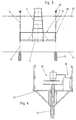
- the floating body 1 has several buoyancy chambers 3, according to the embodiment shown are open at the bottom. Closed buoyancy chambers would also be conceivable and possible.
- the floating body 1 has a circular shape Cover plate 4, along the outer edge of which is an annular Side wall 5 extends.
- the individual buoyancy chambers 3 are radially extending Partitions 6 and an inner annular partition 7 delimited from each other. Other contours of the cover plate and / or shapes the buoyancy chambers 3 are quite conceivable and possible.
- the in the Fig. The floating body shown is only shown symbolically and the shown Wall thicknesses are not to scale.
- the structure 2 carried by the floating foundation can be, for example act as a wind tower of a wind turbine, of which in FIGS. only a lower part is shown.
- anchors 12 could also be independent of Float 1 are attached, for example before the float 1 has been brought to its site.
- Tube 14 attached to the float.
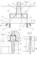
- This can, for example, in the in 7 schematically shown way: Above a respective Passage opening 8 (which may be limited by a tube 15) 4 mounting brackets 16 attached to the cover plate.
- the mounting brackets 16 have for attachment to the cover plate 4 one by means of screws 17 on the cover plate 4 screwed on flange plate 18.
- On the flange plate 18 are after upstanding uprights 19 welded to the upper end of a flange 20 is fixed with a central recess.
- On this flange disc 20 are the tubes 14 by means of one at the lower end of the respective tube welded base plate 21 and flange plate 20 and base plate 21 penetrating screw 22 attached. Are located between the stands 19 mounting holes 23.
- Tubes 14 each have a working platform 24 attached to the tubes 14 (FIG. 6).
- the cables (hawser or ropes) 13 or rods connected to the anchors 12 run through the tubes 14 and extend to above their upper ends.
- the cables 13 or rods were used for this purpose before being attached of the tubes 14 threaded onto the floating body 1 in the tubes 14.
- a pulling device 25 is also provided, which u. a. of a hydraulic device 26 can be actuated.
- Such traction devices 25 are, for example under the names "pre-tensioning press” or “lifting hydraulics" known and commercially available.
- the buoyancy of the float can be reduced by the air volume present in the buoyancy chambers 3 is reduced.
- the water level in the buoyancy chambers is in the Fig. Schematically represented by line 28. Because the lowering of the float 1 takes place against its buoyancy, a certain stabilization of the Float reached when lowering.
- the angle of inclination for example is in a range between 25 and 45 °.
- the anchor 30 for this obliquely to put extending rods or cables 31 (or hawser) is in the lower Area of the building 2 formed an anhydrous area in the manner of a caisson.
- the peripheral wall 32 of the structure 2 is at least in this lower one Area enclosed and watertight and also a waterproof or airtight false ceiling 33 is provided.
- one or more drilling devices are used, which by means of appropriate drilling devices these pipes 35 drill holes in the ground 11 to set the anchor 30.
- these pipes 35 drill holes in the ground 11 to set the anchor 30.
- cables 31 or rods are connected through the Tubes 35 run and are fixed to the floating body 1.
- the work on Attachment of the anchor 30 and rods or cables 31 do not have to Divers are carried out and the work to be carried out by divers can be kept to a minimum.
- Fig. 8 From the detail shown in Fig. 8 is an advantageous embodiment of a passage opening 8 shown in the region of its lower end section.
- the conically widening region 36 over a radius of curvature 37 to the overlying part of the passage opening 8 connects and in the mouth area of the conically widening area 36 a further radius of curvature 38 is provided which widens the opening is.
- the passage openings 8 can also be used in another The position and number of the float must be available. In any case, at least three through openings arranged at the corner points of an imaginary triangle 8 to be provided. This imaginary triangle conveniently spans the central area of the float 1. Also four, six or more Through openings for cables 13 or rods can be provided above of which a tube 14 is fixed, the number of openings 8 also depends on the size of the float. Also one different number of cables 31 inclined to the vertical, which are fixed to anchors 30 and can pass through passage openings 35 be provided. At least three such cables are advantageously 31 or Bars provided along the side edges of an imaginary pyramid run. Also six, eight or more such inclined to the vertical Poles can be provided.
- 9 and 10 show parts of pipes that to form passage openings 8 through the floating body 1 in this be poured.
- a mounting flange 42 is attached at the free end of the connecting shaft 40 in which boreholes are provided are, whereby a closure plate 43 can be screwed on.
- connection opening is now made by removing the closure plate 43 opened so that the cable 13 extending through the passage opening 8 now is accessible from the buoyancy chamber 3.
- the cable (the Hawser) 13 or the rod are clamped and above the clamping device be severed.
- This area can now, for example, by means of of a foaming plastic, waterproof sealed.
- the clamping work can thus be carried out in the dry, and also no salt water can enter the cut cable.
- the work are facilitated and the risk of corrosion is reduced.
- the passage openings 8 can also be located below the connection openings 41 be sealed. After completing the work through the connection opening 41 whose hatch can in turn be closed by the closure plate 43.
- buoyancy body 1 also of several interconnected (for example over a linkage) partial bodies are formed.
Claims (15)
- Procédé pour abaisser dans sa position finale qui se trouve en-dessous de la surface de l'eau (27) le flotteur (1) d'un support flottant, qui supporte une construction (2) dépassant au-dessus de la surface de l'eau, et pour le bloquer dans sa position finale, des ancres (12) étant disposées dans le fond (11), et le flotteur (1) étant retenu par des câbles (13) ou des tiges relié(e)s aux ancres (12), et dans lequel le flotteur (1), qui flotte tout d'abord au niveau de la surface de l'eau (27), comporte au moins trois ouvertures de passage (8) disposées aux sommets des angles d'un triangle imaginaire, caractérisée en ce qu'un tube (14) dépassant vers le haut est fixé au flotteur (1) au-dessus d'une ouverture de passage respective (8) et en ce qu'un câble (13) ou, une tige, est guidé(e) à travers une ouverture de passage (8) et le tube (14) placé au-dessus de l'ouverture de passage (8), qui est relié(e) avant ou après à une ancre (12) disposée dans le fond (11), et en ce qu'un dispositif de traction (25) agissant sur le câble (13) ou, la tige, est prévu dans la zone de l'extrémité supérieure de chaque tube (14), le flotteur (1) étant baissé dans sa position finale contre la force portante du flotteur (1) en-dessous de la surface de l'eau (27) au moyen des dispositifs de traction (25) agissant sur les câbles (13) ou, les tiges, et, lorsque le flotteur (1) se trouve en position finale, les câbles (13) ou, selon les cas, les tiges, étant bloqué(e)s par rapport au flotteur (1), et les segments de câbles (13) ou, de tiges, se trouvant au-dessus de la fixation au niveau du flotteur (1), étant ôtés et les tubes dépassant au-dessus des ouvertures de passage (8) étant déposés.
- Procédé selon la revendication 1, caractérisé en ce que la longueur des tubes (14) est supérieure à la distance qui sépare le flotteur (1) de la surface de l'eau (27) lorsqu'il est dans sa position finale.
- Procédé selon la revendication 1 ou 2, caractérisé en ce que les tubes (14) sont reliés à des consoles de montage (16) fixées au flotteur, qui comportent des ouvertures de montage (23) à travers lesquelles des dispositifs de serrage (29) peuvent être actionnés, qui sont destinés, lorsque le flotteur (1) se trouve dans sa position finale baissée, à fixer les câbles (13) ou, les tiges, au flotteur (1).
- Procédé selon l'une des revendications 1 à 3, caractérisé en ce que le long de la périphérie du flotteur (1) au moins quatre, de préférence au moins six ouvertures de passage (8) disposées dans la zone de bord du flotteur (1) sont prévues, au-dessus desquelles sont fixés des tubes (14) dépassant vers le haut.
- Procédé selon l'une des revendications 1 à 4, caractérisé en ce que l'on utilise des équipements de forage (9) disposés sur la plaque de couverture (4) du flotteur (1) pour la pose des ancres (12) dans le fond (11), équipements qui réalisent des forages pour les ancres (12) dans le fond (11) par l'intermédiaire d'outils de forage (10) guidés dans le flotteur (1) à travers les ouvertures de passage (8).
- Procédé selon l'une des revendications 1 à 5, caractérisé en ce que sont prévu(e)s à proximité des câbles (13) ou des tiges relié(e)s aux ancres (12) et s'étendant sensiblement verticalement, d'autres câbles (31) ou tiges de ce type, qui sont incliné(e)s par rapport à la verticale suivant un angle d'inclinaison compris de préférence entre 25 et 40°.
- Procédé selon la revendication 6, caractérisé en ce qu'un caisson est conçu dans la zone inférieure de la construction (2) pour l'exécution des forages dans le fond (11) pour les ancres (30) des câbles (31) ou des tiges s'étendant sur un plan incliné par rapport à la verticale, depuis lequel les forages sont réalisés par des équipements de forage, les outils de forage étant guidés à travers les ouvertures de passage dans le flotteur (1).
- Procédé selon la revendication 7, caractérisé en ce que la fixation des câbles (31) ou des tiges s'étendant sur un plan incliné par rapport à la verticale et relié(e)s aux ancres (30) s'effectue également dans ce caisson.
- Procédé selon l'une des revendications 1 à 8, caractérisé en ce que, lorsque le flotteur (1) est abaissé, sa force portante est réduite par rapport à celle qu'il présente en position finale.
- Procédé selon l'une des revendications 1 à 9, caractérisé en ce qu'il est prévu une ouverture de communication refermable (41) entre une ouverture de passage respective (8) à travers le flotteur (1) et l'une des chambres de sustentation (3) du flotteur (1) pour l'exécution des travaux de fixation des câbles (13, 31) ou des tiges au niveau du flotteur (1).
- Procédé selon la revendication 10, caractérisé en ce que l'ouverture de passage (8) est fermée de façon étanche en-dessous et/ou au-dessus de l'ouverture de communication (41), le niveau de l'eau dans l'ouverture de passage (8) étant baissé en-dessous du dispositif de serrage lors de la fixation du câble respectif (13, 31) ou, de la tige respective.
- Procédé selon la revendication 10 ou 11, caractérisé en ce que pour l'exécution des travaux de fixation des câbles (13, 31) ou des tiges, le niveau de l'eau est baissé dans la chambre de sustentation respective (3) depuis laquelle les travaux sont chaque fois réalisés, le niveau d'eau étant ce faisant de préférence relevé dans au moins l'une des chambres de sustentation ou de portance (3) voisines pour compenser.
- Procédé selon l'une des revendications 1 à 12, caractérisé en ce que les ouvertures de passage (8) dans le flotteur (1) sont formées par des tubes (39) coulés dans le flotteur (1).
- Dispositif pour baisser dans sa position finale qui se trouve en-dessous de la surface de l'eau le flotteur d'un support flottant, qui supporte une construction dépassant au-dessus de la surface de l'eau, des ancres (12) étant prévues dans le fond (11), et le flotteur (1) étant retenu par des câbles (13) ou des tiges relié(e)s aux ancres (12), caractérisé en ce que des tubes à installer (14) sont prévus au-dessus d'ouvertures de passage (8) s'étendant à travers le flotteur (1) dont les extrémité supérieures sont associées à des dispositifs de traction (25) au moyen desquels les câbles (13) ou les tiges s'étendant à travers les ouvertures de passage (8) et les tubes (14) fixé(e)s aux ancres (12) peuvent être retiré(e)s des tubes (14).
- Dispositif selon la revendication 14, caractérisé en ce qu'une plate-forme de travail (24) est prévue dans la zone des extrémités supérieures des tubes (14), respectivement supportée par ceux-ci.
Applications Claiming Priority (4)
| Application Number | Priority Date | Filing Date | Title |
|---|---|---|---|
| AT2312002 | 2002-02-14 | ||
| AT2312002 | 2002-02-14 | ||
| AT8322002 | 2002-05-31 | ||
| AT8322002 | 2002-05-31 |
Publications (2)
| Publication Number | Publication Date |
|---|---|
| EP1336559A1 EP1336559A1 (fr) | 2003-08-20 |
| EP1336559B1 true EP1336559B1 (fr) | 2004-08-04 |
Family
ID=27623500
Family Applications (1)
| Application Number | Title | Priority Date | Filing Date |
|---|---|---|---|
| EP03001997A Expired - Lifetime EP1336559B1 (fr) | 2002-02-14 | 2003-01-31 | Méthode pour baisser sous l'eau le flotteur d'un support flottant |
Country Status (6)
| Country | Link |
|---|---|
| US (1) | US6773207B2 (fr) |
| EP (1) | EP1336559B1 (fr) |
| JP (1) | JP4043380B2 (fr) |
| AT (1) | ATE272525T1 (fr) |
| DE (1) | DE50300043D1 (fr) |
| DK (1) | DK1336559T3 (fr) |
Cited By (1)
| Publication number | Priority date | Publication date | Assignee | Title |
|---|---|---|---|---|
| CN103119222A (zh) * | 2010-07-05 | 2013-05-22 | 船舶通用涡轮有限公司 | 用于安装一个或多个浸没柱/桩的可再用的打破表面的可浸没模板 |
Families Citing this family (12)
| Publication number | Priority date | Publication date | Assignee | Title |
|---|---|---|---|---|
| ITBA20040027U1 (it) * | 2004-10-06 | 2005-01-06 | Enertec Ag | (metodo di) realizzazione di piattaforma sommergibile a spinta bloccata da utilizzarsi quale supporto per l'installazione di aerogeneratore , di elettrolizzatore per l'elettrolisi dell'acqua e di altri impianti e/o macchinari , combinata con attivita |
| WO2008077405A1 (fr) * | 2006-12-22 | 2008-07-03 | Vestas Wind Systems A/S | Système d'amarrage pour stabiliser un navire, navire, procédé pour stabiliser un navire et utilisation d'un système d'amarrage |
| NO329946B1 (no) * | 2008-08-14 | 2011-01-31 | Olav Olsen As Dr Techn | Fundament for en vindturbingenerator til havs samt fremgangsmate for bygging og installasjon av fundamentet |
| CN101748748B (zh) * | 2010-01-21 | 2011-09-14 | 道达(上海)风电投资有限公司 | 一种内置浮筒的筒型基础气浮拖航方法 |
| CN102704503A (zh) * | 2012-05-30 | 2012-10-03 | 天津大学 | 海上潜式箱型基础结构及其施工方法 |
| CN102704506B (zh) * | 2012-05-30 | 2014-07-16 | 天津大学 | 海上潜式基础结构的施工方法 |
| CN102677693B (zh) * | 2012-05-30 | 2014-06-25 | 天津大学 | 一种海上潜式基础结构的施工方法 |
| CN102704502A (zh) * | 2012-05-30 | 2012-10-03 | 天津大学 | 一种海上潜式箱型基础结构及其施工方法 |
| CA2897267C (fr) * | 2013-01-22 | 2016-09-06 | Zhirong Wu | Cylindre unitaire de plaque d'acier et de structure composite en beton, groupe de cylindres unitaires et plate-forme offshore |
| CN103195110B (zh) * | 2013-03-29 | 2015-02-11 | 天津大学 | 一种稳定筒型基础下沉负压的试验装置 |
| DK3212862T3 (da) * | 2014-10-31 | 2019-07-29 | Soletanche Freyssinet | Fremgangsmåde til fremstilling af betonkonstruktionsblokke til et vindmølletårn og associeret system |
| CN104652499A (zh) * | 2015-02-06 | 2015-05-27 | 天津大学 | 一种模拟桶形基础负压沉贯过程的实验装置及实验方法 |
Family Cites Families (9)
| Publication number | Priority date | Publication date | Assignee | Title |
|---|---|---|---|---|
| US3086368A (en) * | 1958-10-08 | 1963-04-23 | Popper Otto | Chains and marine apparatus moored or anchored by chains to the sea bed |
| US4473323A (en) * | 1983-04-14 | 1984-09-25 | Exxon Production Research Co. | Buoyant arm for maintaining tension on a drilling riser |
| US4604001A (en) * | 1984-03-08 | 1986-08-05 | Global Marine Inc. | Jackdown tension leg platform |
| US4657439A (en) * | 1985-12-18 | 1987-04-14 | Shell Offshore Inc. | Buoyant member riser tensioner method and apparatus |
| JPH06255573A (ja) | 1993-03-09 | 1994-09-13 | Kajima Corp | 水上構築物の繋留方法 |
| NO309233B1 (no) * | 1995-06-07 | 2001-01-02 | Aker Eng As | Fremgangsmåte ved installasjon av strekkstagplattform |
| US5964550A (en) | 1996-05-31 | 1999-10-12 | Seahorse Equipment Corporation | Minimal production platform for small deep water reserves |
| ATE467551T1 (de) * | 2001-08-30 | 2010-05-15 | Rund Stahl Bau Gmbh & Co | Schwimmfundament für ein über die wasseroberfläche aufragendes bauwerk |
| JP2009021648A (ja) | 2007-07-10 | 2009-01-29 | Kojima Press Co Ltd | 車両用アンテナ装置およびそのアンテナエレメントとケーブルの接続方法 |
-
2003
- 2003-01-31 EP EP03001997A patent/EP1336559B1/fr not_active Expired - Lifetime
- 2003-01-31 AT AT03001997T patent/ATE272525T1/de not_active IP Right Cessation
- 2003-01-31 DK DK03001997T patent/DK1336559T3/da active
- 2003-01-31 DE DE50300043T patent/DE50300043D1/de not_active Expired - Lifetime
- 2003-02-12 US US10/365,792 patent/US6773207B2/en not_active Expired - Fee Related
- 2003-02-14 JP JP2003036486A patent/JP4043380B2/ja not_active Expired - Fee Related
Cited By (1)
| Publication number | Priority date | Publication date | Assignee | Title |
|---|---|---|---|---|
| CN103119222A (zh) * | 2010-07-05 | 2013-05-22 | 船舶通用涡轮有限公司 | 用于安装一个或多个浸没柱/桩的可再用的打破表面的可浸没模板 |
Also Published As
| Publication number | Publication date |
|---|---|
| JP2003268791A (ja) | 2003-09-25 |
| JP4043380B2 (ja) | 2008-02-06 |
| DK1336559T3 (da) | 2004-11-08 |
| DE50300043D1 (de) | 2004-09-09 |
| ATE272525T1 (de) | 2004-08-15 |
| EP1336559A1 (fr) | 2003-08-20 |
| US6773207B2 (en) | 2004-08-10 |
| US20030152429A1 (en) | 2003-08-14 |
Similar Documents
| Publication | Publication Date | Title |
|---|---|---|
| EP1288122B1 (fr) | Support flottant pour une construction s'élevant au dessus de la surface de l'eau | |
| EP1336559B1 (fr) | Méthode pour baisser sous l'eau le flotteur d'un support flottant | |
| EP2831342B1 (fr) | Procédé de manipulation d'un amortisseur de sons émis sous l'eau et dispositif pour réduire les sons dans l'eau | |
| DE102012202132B4 (de) | Verfahren und Vorrichtung zum Schallschutz | |
| DE1917819A1 (de) | Unterwasserstandrohr fuer Unterwasser-Tiefbohrungen | |
| EP3198083B1 (fr) | Amortisseur de sons émis sous l'eau et procédé de manipulation d'un amortisseur de sons émis sous l'eau | |
| DE1926001A1 (de) | Vorrichtung zum Herstellen einer Verbindung zwischen einem Unterwasser-Produktionsbohrlochkopf und einem darueber schwimmenden Fahrzeug | |
| DE2644725A1 (de) | Bohrinsel | |
| DE2728128A1 (de) | Verfahren zum giessformen langgestreckter, mit geschlossenen enden versehener tanks aus beton im meerwasser und vorrichtung zur durchfuehrung des verfahrens | |
| DE2365445C2 (de) | Verfahren zur Herstellung eines Sanddräns sowie Rüttelramme zur Durchführung des Verfahrens | |
| DE1558965B2 (de) | Kuestenfernes Bohrsystem | |
| DE2512865A1 (de) | Aufblaseinrichtung fuer in den pfahlhuelsen von off-shore-plattformen befindliche stopfbuechsenpackungen | |
| DE2656959A1 (de) | Verankerbare schwimmplattform | |
| DE2325020A1 (de) | Grundbauteil fuer eine bohrinsel | |
| DE2452161A1 (de) | Kuenstliche insel | |
| DE2005960A1 (de) | Anlage einer Gruppe von Unterwasser-Bohrlöchern | |
| DE2439576A1 (de) | Bohrinsel | |
| DE102007037476A1 (de) | Wasserschutzwall gegen Hochwasser | |
| EP2020463A1 (fr) | Batardeau-caisson et procédé de protection d'une construction offshore contre l'eau environnante en utilisant celui-ci | |
| DE19525590C2 (de) | Herstellung einer Baugrube mit Verankerungen unterhalb des Grundwasserspiegels | |
| DE1232087B (de) | Rohrsystem fuer Unterwasser-Tiefbohrungen | |
| EP3061870A1 (fr) | Systeme de protection d'immeubles contre les crues | |
| EP0099938B1 (fr) | Substructure sous-marine et son installation en grandes profondeurs, pour des plate-formes auto-élévatrices en mer | |
| DE2323135A1 (de) | Verfahren zum errichten eines turmes od. dgl. auf dem meeresboden | |
| DE4219078A1 (de) | Verfahren und Vorrichtung zum Errichten eines Bauwerkes in Grundwasser |
Legal Events
| Date | Code | Title | Description |
|---|---|---|---|
| PUAI | Public reference made under article 153(3) epc to a published international application that has entered the european phase |
Free format text: ORIGINAL CODE: 0009012 |
|
| AK | Designated contracting states |
Designated state(s): AT BE BG CH CY CZ DE DK EE ES FI FR GB GR HU IE IT LI LU MC NL PT SE SI SK TR |
|
| AX | Request for extension of the european patent |
Extension state: AL LT LV MK RO |
|
| 17P | Request for examination filed |
Effective date: 20031124 |
|
| GRAP | Despatch of communication of intention to grant a patent |
Free format text: ORIGINAL CODE: EPIDOSNIGR1 |
|
| GRAJ | Information related to disapproval of communication of intention to grant by the applicant or resumption of examination proceedings by the epo deleted |
Free format text: ORIGINAL CODE: EPIDOSDIGR1 |
|
| GRAP | Despatch of communication of intention to grant a patent |
Free format text: ORIGINAL CODE: EPIDOSNIGR1 |
|
| AKX | Designation fees paid |
Designated state(s): AT BE BG CH CY CZ DE DK EE ES FI FR GB GR HU IE IT LI LU MC NL PT SE SI SK TR |
|
| GRAS | Grant fee paid |
Free format text: ORIGINAL CODE: EPIDOSNIGR3 |
|
| GRAA | (expected) grant |
Free format text: ORIGINAL CODE: 0009210 |
|
| AK | Designated contracting states |
Kind code of ref document: B1 Designated state(s): AT BE BG CH CY CZ DE DK EE ES FI FR GB GR HU IE IT LI LU MC NL PT SE SI SK TR |
|
| PG25 | Lapsed in a contracting state [announced via postgrant information from national office to epo] |
Ref country code: IT Free format text: LAPSE BECAUSE OF FAILURE TO SUBMIT A TRANSLATION OF THE DESCRIPTION OR TO PAY THE FEE WITHIN THE PRESCRIBED TIME-LIMIT;WARNING: LAPSES OF ITALIAN PATENTS WITH EFFECTIVE DATE BEFORE 2007 MAY HAVE OCCURRED AT ANY TIME BEFORE 2007. THE CORRECT EFFECTIVE DATE MAY BE DIFFERENT FROM THE ONE RECORDED. Effective date: 20040804 Ref country code: SK Free format text: LAPSE BECAUSE OF FAILURE TO SUBMIT A TRANSLATION OF THE DESCRIPTION OR TO PAY THE FEE WITHIN THE PRESCRIBED TIME-LIMIT Effective date: 20040804 Ref country code: IE Free format text: LAPSE BECAUSE OF FAILURE TO SUBMIT A TRANSLATION OF THE DESCRIPTION OR TO PAY THE FEE WITHIN THE PRESCRIBED TIME-LIMIT Effective date: 20040804 Ref country code: TR Free format text: LAPSE BECAUSE OF FAILURE TO SUBMIT A TRANSLATION OF THE DESCRIPTION OR TO PAY THE FEE WITHIN THE PRESCRIBED TIME-LIMIT Effective date: 20040804 Ref country code: EE Free format text: LAPSE BECAUSE OF FAILURE TO SUBMIT A TRANSLATION OF THE DESCRIPTION OR TO PAY THE FEE WITHIN THE PRESCRIBED TIME-LIMIT Effective date: 20040804 Ref country code: SI Free format text: LAPSE BECAUSE OF FAILURE TO SUBMIT A TRANSLATION OF THE DESCRIPTION OR TO PAY THE FEE WITHIN THE PRESCRIBED TIME-LIMIT Effective date: 20040804 Ref country code: BG Free format text: LAPSE BECAUSE OF FAILURE TO SUBMIT A TRANSLATION OF THE DESCRIPTION OR TO PAY THE FEE WITHIN THE PRESCRIBED TIME-LIMIT Effective date: 20040804 Ref country code: FR Free format text: LAPSE BECAUSE OF FAILURE TO SUBMIT A TRANSLATION OF THE DESCRIPTION OR TO PAY THE FEE WITHIN THE PRESCRIBED TIME-LIMIT Effective date: 20040804 Ref country code: CZ Free format text: LAPSE BECAUSE OF FAILURE TO SUBMIT A TRANSLATION OF THE DESCRIPTION OR TO PAY THE FEE WITHIN THE PRESCRIBED TIME-LIMIT Effective date: 20040804 Ref country code: FI Free format text: LAPSE BECAUSE OF FAILURE TO SUBMIT A TRANSLATION OF THE DESCRIPTION OR TO PAY THE FEE WITHIN THE PRESCRIBED TIME-LIMIT Effective date: 20040804 |
|
| REG | Reference to a national code |
Ref country code: GB Ref legal event code: FG4D Free format text: NOT ENGLISH |
|
| REG | Reference to a national code |
Ref country code: CH Ref legal event code: EP |
|
| REG | Reference to a national code |
Ref country code: IE Ref legal event code: FG4D Free format text: GERMAN |
|
| REF | Corresponds to: |
Ref document number: 50300043 Country of ref document: DE Date of ref document: 20040909 Kind code of ref document: P |
|
| PG25 | Lapsed in a contracting state [announced via postgrant information from national office to epo] |
Ref country code: SE Free format text: LAPSE BECAUSE OF FAILURE TO SUBMIT A TRANSLATION OF THE DESCRIPTION OR TO PAY THE FEE WITHIN THE PRESCRIBED TIME-LIMIT Effective date: 20041104 Ref country code: GR Free format text: LAPSE BECAUSE OF FAILURE TO SUBMIT A TRANSLATION OF THE DESCRIPTION OR TO PAY THE FEE WITHIN THE PRESCRIBED TIME-LIMIT Effective date: 20041104 |
|
| PG25 | Lapsed in a contracting state [announced via postgrant information from national office to epo] |
Ref country code: HU Free format text: LAPSE BECAUSE OF FAILURE TO SUBMIT A TRANSLATION OF THE DESCRIPTION OR TO PAY THE FEE WITHIN THE PRESCRIBED TIME-LIMIT Effective date: 20041105 |
|
| REG | Reference to a national code |
Ref country code: DK Ref legal event code: T3 |
|
| PG25 | Lapsed in a contracting state [announced via postgrant information from national office to epo] |
Ref country code: ES Free format text: LAPSE BECAUSE OF FAILURE TO SUBMIT A TRANSLATION OF THE DESCRIPTION OR TO PAY THE FEE WITHIN THE PRESCRIBED TIME-LIMIT Effective date: 20041115 |
|
| GBT | Gb: translation of ep patent filed (gb section 77(6)(a)/1977) |
Effective date: 20041112 |
|
| PG25 | Lapsed in a contracting state [announced via postgrant information from national office to epo] |
Ref country code: CY Free format text: LAPSE BECAUSE OF FAILURE TO SUBMIT A TRANSLATION OF THE DESCRIPTION OR TO PAY THE FEE WITHIN THE PRESCRIBED TIME-LIMIT Effective date: 20050131 Ref country code: MC Free format text: LAPSE BECAUSE OF NON-PAYMENT OF DUE FEES Effective date: 20050131 Ref country code: AT Free format text: LAPSE BECAUSE OF NON-PAYMENT OF DUE FEES Effective date: 20050131 Ref country code: LU Free format text: LAPSE BECAUSE OF NON-PAYMENT OF DUE FEES Effective date: 20050131 |
|
| REG | Reference to a national code |
Ref country code: IE Ref legal event code: FD4D |
|
| PLBE | No opposition filed within time limit |
Free format text: ORIGINAL CODE: 0009261 |
|
| STAA | Information on the status of an ep patent application or granted ep patent |
Free format text: STATUS: NO OPPOSITION FILED WITHIN TIME LIMIT |
|
| 26N | No opposition filed |
Effective date: 20050506 |
|
| EN | Fr: translation not filed | ||
| PG25 | Lapsed in a contracting state [announced via postgrant information from national office to epo] |
Ref country code: CH Free format text: LAPSE BECAUSE OF NON-PAYMENT OF DUE FEES Effective date: 20070131 Ref country code: LI Free format text: LAPSE BECAUSE OF NON-PAYMENT OF DUE FEES Effective date: 20070131 |
|
| REG | Reference to a national code |
Ref country code: CH Ref legal event code: PL |
|
| PG25 | Lapsed in a contracting state [announced via postgrant information from national office to epo] |
Ref country code: PT Free format text: LAPSE BECAUSE OF NON-PAYMENT OF DUE FEES Effective date: 20050104 |
|
| PGFP | Annual fee paid to national office [announced via postgrant information from national office to epo] |
Ref country code: DE Payment date: 20120620 Year of fee payment: 10 Ref country code: DK Payment date: 20120529 Year of fee payment: 10 Ref country code: NL Payment date: 20120604 Year of fee payment: 10 |
|
| PGFP | Annual fee paid to national office [announced via postgrant information from national office to epo] |
Ref country code: GB Payment date: 20120523 Year of fee payment: 10 |
|
| PGFP | Annual fee paid to national office [announced via postgrant information from national office to epo] |
Ref country code: BE Payment date: 20120628 Year of fee payment: 10 |
|
| BERE | Be: lapsed |
Owner name: *RUND-STAHL-BAU G.M.B.H. Effective date: 20130131 |
|
| REG | Reference to a national code |
Ref country code: NL Ref legal event code: V1 Effective date: 20130801 |
|
| REG | Reference to a national code |
Ref country code: DK Ref legal event code: EBP |
|
| GBPC | Gb: european patent ceased through non-payment of renewal fee |
Effective date: 20130131 |
|
| PG25 | Lapsed in a contracting state [announced via postgrant information from national office to epo] |
Ref country code: BE Free format text: LAPSE BECAUSE OF NON-PAYMENT OF DUE FEES Effective date: 20130131 Ref country code: DE Free format text: LAPSE BECAUSE OF NON-PAYMENT OF DUE FEES Effective date: 20130801 Ref country code: NL Free format text: LAPSE BECAUSE OF NON-PAYMENT OF DUE FEES Effective date: 20130801 |
|
| REG | Reference to a national code |
Ref country code: DE Ref legal event code: R119 Ref document number: 50300043 Country of ref document: DE Effective date: 20130801 |
|
| PG25 | Lapsed in a contracting state [announced via postgrant information from national office to epo] |
Ref country code: GB Free format text: LAPSE BECAUSE OF NON-PAYMENT OF DUE FEES Effective date: 20130131 |
|
| PG25 | Lapsed in a contracting state [announced via postgrant information from national office to epo] |
Ref country code: DK Free format text: LAPSE BECAUSE OF NON-PAYMENT OF DUE FEES Effective date: 20130131 |