EP1336370A2 - Verschwenkbar im Geschirrkorb einer Geschirrspülmaschine angeordnetes Anlageelement - Google Patents
Verschwenkbar im Geschirrkorb einer Geschirrspülmaschine angeordnetes Anlageelement Download PDFInfo
- Publication number
- EP1336370A2 EP1336370A2 EP03001145A EP03001145A EP1336370A2 EP 1336370 A2 EP1336370 A2 EP 1336370A2 EP 03001145 A EP03001145 A EP 03001145A EP 03001145 A EP03001145 A EP 03001145A EP 1336370 A2 EP1336370 A2 EP 1336370A2
- Authority
- EP
- European Patent Office
- Prior art keywords
- dish rack
- base rod
- contact element
- dishwasher according
- stop
- Prior art date
- Legal status (The legal status is an assumption and is not a legal conclusion. Google has not performed a legal analysis and makes no representation as to the accuracy of the status listed.)
- Granted
Links
Images



Classifications
-
- A—HUMAN NECESSITIES
- A47—FURNITURE; DOMESTIC ARTICLES OR APPLIANCES; COFFEE MILLS; SPICE MILLS; SUCTION CLEANERS IN GENERAL
- A47L—DOMESTIC WASHING OR CLEANING; SUCTION CLEANERS IN GENERAL
- A47L15/00—Washing or rinsing machines for crockery or tableware
- A47L15/42—Details
- A47L15/50—Racks ; Baskets
- A47L15/503—Racks ; Baskets with foldable parts
Definitions
- the invention relates to a pivotable in the crockery basket arranged in accordance with a dishwasher the preamble of claim 1.
- a crockery basket of a dishwasher at least one investment element, which at least comprises a base staff and an investment staff. That is preferable Includes system element designed as a plate rake a base rod and several spikes as contact rods.
- the spines are used in the dishes basket set plates or other wash ware as an attachment and thus as a support option.
- the base bar is at least partly over the length or width of the crockery basket arranged, the spines connected to it from Stand the base rod at an angle. The pivoting of the Plate raking is done around the axis of the base bar, the especially coupled to the wire rack of the crockery basket is.
- the non-use position of the plate rake corresponds a position close to the basket floor, preferably horizontal Position, which is an angle of 0 ° or 180 ° in the coordinate system equivalent.
- the plate rake is in principle from the non-use position to the use position and reversely pivotable.
- the pivoting from the position of use which is approximately an angle of 90 ° in the coordinate system corresponds and preferred the vertical position includes, can thus generally to the right or on the left, whereby the plate rake is flipped to the right the angular range of the first quadrant of the coordinate system in a closed interval from 90 ° to 0 ° and moving the plate rake to the left of the second Quadrants of the coordinate system in the closed interval sweeps from 90 ° to 180 °.
- the base of the Contact element is designed as a spring element or on the contact element acts at least one spring element in such a way that the contact element is tensioned in the position of use. In order to prevent the investment element from being assigned to it Swivel range, i.e.
- an angular range between the position of use and non-use position which is therefore either between 90 ° and 0 ° or 90 ° and 180 °, leaves automatically, at least one stop is provided.
- both a pivoting range of 0 ° to 90 ° and 90 ° to 180 ° are provided comprises at least two stops in the position of use. Since that In principle, the plant element also when it is not in use can escape from its pivoting range is preferred also a stop for the limitation when not in use, hereinafter referred to as stop N, arranged. In the non-use position can be used as a stop N existing floor of the crockery basket can be used. On Another stop for fixing the contact element in The position of use is referred to below as stop G.
- a defined angle between 90 ° and 0 ° or 90 ° and 180 ° corresponds to a stress situation of the contact element, in which the tension of the contact element has a maximum.
- the stress situation is due to the type of voltage generation on the contact element freely definable.
- a voltage maximum in the swivel range has the advantage that the contact element derives from its stress situation automatically in the use position or in the non-use position moves, which creates a kind of snap effect, so that a cumbersome and unwieldy lifting into a fixing device is not necessary.
- the natural striving of the investment element in its tension-free rest position, that of the stress situation opposite and therefore below the basket floor is in any case by the one used as the stop N. Basket bottom prevented.
- the voltage acting on the contact element from the outside becomes particularly preferably mainly on the base rod Recording elements exercised.
- a voltage generation through Exercise this on other parts of the investment element, e.g. B. on the spikes of the plate rake or other plant bars is possible, too. If spring elements are arranged, this acts the tension mainly on this, the tension effect from the outside onto the base rod is much less.
- the base rod is particularly advantageous in at least one End piece bent, the bent end piece doing the function of the stop G can exert a striving for the contact element prevented from its position of use by against the basket floor or other struts of the crockery basket encounters.
- a crank cranked which does not align the base rod and their orientation the stress or rest position of the Determines investment element.
- the base rod is predominantly d. H. between its two end pieces, symmetrical bent and has a bent at one end piece Stop G on. In a further preferred embodiment there is also a stop G at one end piece bent and a crank is cranked at the other end piece.
- the stop G which is an automatic movement of the Investment element, the following in its nature as a snap or snapping away movement from which prevents vertical use, not as in a preferred Embodiment molded onto the base rod in the end piece, this stop G is separated from the base bar provided another place of the crockery basket. Is the Stop G on the base rod is arranged as a counter stop for this by appropriate design either the axles of the wheels or a wire of the side walls or the bottom of the crockery basket. Is this not possible, i.e. the stop G is an additional element on Dish basket arranged, then serve as a counterstop Base rod or at least a spike or other element of the investment element.
- the one to be clamped on the crockery basket is particularly preferred Base bar before its storage in this already by appropriate Deformation into an internal state of stress offset, i.e. biased.
- the base bar is in front of it Storage in the crockery basket in any case not as a straight one Wire, but e.g. arched.
- At least act three receiving elements and / or spring elements, the non-aligned in a clamped with the base rod Level are arranged on the non-straight and under inner Tensions stand and are the cause the overall state of stress acting on the base rod, which the movement of the contact element with the above Snap effect enables.
- the receiving elements are, for example as hook-like depressions or depressions a strut of the crockery basket or as a separately arranged Brackets and / or spring elements executed.
- the spring elements are designed as tongues, for example. Free deformable wires that are several of the above-mentioned receiving elements and / or absorb spring elements and are with attached to the crockery basket so that they e.g. on different Investment elements work. Are the three recording elements or spring elements not in alignment, so lay these receiving and / or spring elements, caused by the choice of their arrangement, the stress level of the base bar and thus the location of its maximum voltage.
- the determination of the stress situation continues as before described above in the angular range of the pivoting. Towards for example, an investment element from the position of use swiveled to the right into the non-use position, so it is Stress situation with an angle between 0 ° and 90 ° set, it being particularly advantageous if the Stress situation at least the approximately right angle divides between use and non-use position at 45 ° or the angle between the non-use and stress position is chosen larger than 45 ° because of the snap effect the shorter the distance, the greater the closer the stress situation is is due to the position of use.
- a holding receiving or spring element acts as a support Pressure point on the base rod from below during the adjacent pressing receiving and / or spring elements press on it from above and thus as the upper pressure points Act.
- the receiving and / or spring elements are the most pressing Receiving and / or spring elements conveniently as a fixed bearing designed for an X and Y coordinate, where the X coordinate in the direction of the horizontal, the Y coordinate towards the vertical and the Z coordinate points in the direction of the pivot axis of the base rod, wherein the latter is free.
- the receiving camp is then as halfless bearing designed, this is a movement of the Contact element in the Y direction, in one orientation, i.e. prevented above or below the crockery basket bottom.
- two bearings as fixed bearings and one bearing as semi-loose Bearing executed as a semi-free bearing can be a cross or Longitudinal strut of the crockery basket base serve while for the fixed bearing receiving elements e.g. arranged in the form of brackets are.
- the base bar can at least a trough stored in the crockery basket and also a hold-down be provided so that trough and hold-down for the base rod form a fixed bearing.
- a spring element acting as a fixed bearing on the base rod is in a further preferred embodiment as a tongue designed. It is also advantageous that spring elements and / or receiving elements by suitable shaping e.g. formed from a wire and arranged in the crockery basket are that several receiving elements arranged on the wire on different base rods from several planned system elements, e.g. Plate rake, work at the same time. So is it constructively e.g. particularly easy at the ends of a Wire piece to arrange a receiving element. on the other hand can be skilfully formed by Longitudinal struts of the crockery basket base to hold the and / or spring elements are molded so that additional Material expenditure remains limited to this.
- a spring or receiving element act such that with the arrangement of two further receiving elements approximately in The height of the base of the crockery basket, in turn, is not stored in alignment and thus depending on the position of the crank is excited.
- the pivoting of the contact element and thus the plate rake from its non-use position to the use position as well as from the use position to the non-use position is done by manual intervention. From the above the result is that the force applied is sufficient in order to overcome the stress situation of the contact element, the contact element when the stress level is reached can be released and the contact element then automatically in the use or non-use position snaps, the preferred direction in which the contact element snaps, mainly by the trend-setting Type of manual intervention is determined.
- the contact element in the position of use in a fixing element with at least a trough-shaped indentation snaps.
- the trough-shaped Indentation has the advantage that the two-sided Boundary areas of the trough the contact element as two stops G and thus next to the support point of a first Stop G, further support point for the contact element in Use position are present, which mainly to do so serve, a folding of the plate rake by a light, to prevent accidental bumping.
- the Muldenberg thus provides a in the use position for the contact element kind of additional security threshold, whereby towards is to ensure that the stress situation is determined so that the contact element automatically in the position of use can snap.
- two fixing elements and another Stop G stop are another Stop G stop.
- the trough is particularly advantageous because of its low construction Effort, preferably in a basket existing element integrated, otherwise it must be separate be arranged as a fixing element.
- At least one further stop Z is arranged. If this stop Z is arranged on the base rod, it can with a particular advantage that the Prevent the base rod in its free coordinate axis Z, by the stop Z against a strut of the crockery basket strikes.
- the stop Z through the contact element be realized in itself, so that e.g. the side each outer spike of the plate rake slipping out of the contact element by striking the outer Prevents spikes on the side walls of the crockery basket.
- the stop Z can be arranged accordingly next to the stop G, the position of the contact element in the position of use additionally stabilize in one point.
- the stop Z can also be used as a special advantage Fastening device for immersing the wire base frame the basket in a plastic mixture for training be made of a plastic coating.
- the fixed bearings of the base rod are preferably in the form of brackets or other elements of the crockery basket, e.g. wires with appropriate shapes for the storage of the base rod, executed, the wires being components at the same time the bottom of the crockery basket.
- the halfless camp and Spring elements are preferred by individual as mentioned above Struts formed the bottom of the crockery basket.
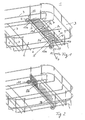
- a crockery basket 1 is not shown Dishwasher shown for the purpose of better Overview not complete and only with its for that Understanding of the invention essential components of the baskets 2, side walls 3, impellers 4, axis 5 of the Impellers 4, longitudinal struts 6, cross struts 7, longitudinal and Cross struts (6,7) form the crockery basket bottom and theirs Ends that are partially reshaped components of the side walls 3 are shown.
- an investment element is a Plate rake 8 pivotably arranged in the crockery basket 1, this is in a non-use position, in which the plate rake 8a in the crockery basket 1 is folded down and consequently no plates, but rather large wash ware, e.g. Pots in the crockery basket 1 can be placed.
- the plate rake 8 basically consists of a non-straight one Base rod 9 and several spines arranged on it 10, at a definable angle from the base bar 9 stand out, with individual adjacent spines 10 parallel lie to each other in such a way that they match the set Dishwashing in the position of use shown in FIG. 2 is a preferred position give.
- the plate rake 8a is in Fig. 1 in almost horizontal non-use position, being exemplary it is shown that different cross struts 6 as a stop N serve and prevent further movement of the plate rake 8a.
- a stop G 11 At one end of the base rod 9.9a is a stop G 11 arranged. As intended, the G 11 stop exercises Non-use position does not stop its stop function. It In terms of design, attention is paid to the fact that the stop G 11 a pivoting of the plate rake 8 between horizontal non-use position and vertical use position not disabled.
- the coordinate system 12 shown serves for reference the directions in the description.
- the plate rake 8, 8a-d is by arranging its base rod 9, 9a-d in the three Receiving elements 13a, 14a and 13b on the crockery basket base 2 pivoted and due to the non-aligned arrangement the receiving elements 13a, 14a, 13b stretched in an arc.
- the receiving elements 13a, 14a, 13b act with respect of the drawn coordinate system 12 for the base bar 9, 9a in the X and Y directions as a fixed bearing. In the X and Y directions change the pressure points of the neighboring recording elements each in one orientation.
- the receiving elements 13a, 14a and 13b shown are from Type holding - pressing - holding, with the receiving elements 13a and 13b support the base rod 9a while the receiving element 14a presses on the base rod 9a and thus alternately lower and upper pressure points on the Base rod 9a act. It follows from the above that for the tensioned state of the non-straight, prestressed base bar 9a the non-aligned arrangement of the receiving elements 13a, 14a and 13b is the cause.
- the invention is essential that during pivoting the plate rake 8 from the non-use position 8a in the position of use 8b, cf. Fig.2, different strong stresses are exerted on the base rod 9a-c or 9a-9d become.
- the base rod is in the non-use position shown 9a excited when moving the plate rake 9b in the position of use, cf. Fig.2, this is experienced by manual Initially, an increase in tension engaging in a Stress situation of the plate rake 9c, cf. Figure 3, reached a maximum. If the plate rake 9c in the stress position released, he can automatically in the position of use 9b move or snap and will here determined by the G 11 stop. In use position 9b has the tension of the base rod 9b compared to the stress position 9c reduced. The G 11 stop prevents a natural striving of the base rod 9 and thus the Plate rake 8 in a de-energized position 8d, cf. Fig. 4. The tensioned state of the base rod 9a-c and the support effect of the G 11 stop allow an almost play-free and thus wobble-free positioning of the base rod 9b and thus the plate rake 8b in the position of use.
- Each piece of wire 19 also connects the holding receiving element 13a with a pressing receiving element 14b and a pressing receiving element 14a with a holding receiving element 13c in such a way that the examples indicated Receiving elements 14b, 13c and another one, not shown pressing receiving element to show the possibility to be able to accommodate another base rod, whereby the receiving elements 14b, 13c and that not shown pressing receiving element pressing-holding-pressing on one further base rod, not shown, would act.
- the wire piece 19 thus shows a particularly simple embodiment several receiving elements on different base bars to act simultaneously.
- alternately pressing or holding onto the base rod i.e. act with different pressure points, is therefore the position of the maximum stress in the stress position and the resulting state of tension in Non-use or use position for the contact element determinable.
- Figure 2 shows a section of the crockery basket 1 after Figure 1, the plate rake 8b in almost vertical Use position is shown.
- the plate rake 8b is between Non-use and use position in an area between 0 ° and 90 ° swiveling, the stop G 11 the plate rake 8b only in the vertical position of use and an automatic snapping or folding the plate rake 8b to the left prevented.
- the base bar 9b points in relation to its stress position shown in FIG. 3 9c a reduced voltage.
- Figure 3 shows a crockery basket 1 according to Figure 1, the Disc rake 8 shown in a stress position 8c is.
- the angle between the non-use and stress position is approximately 45 °.
- the angle in the stress position approx. 45 ° to the horizontal and can with the angle, which the spikes 10 occupy with the horizontal coincide.
- the Position of the stop G 11 changed. This is located However, it does not have a stop function in the stress situation. It cannot be represented that the base rod 9c and therefore the entire plate rake 8c as mentioned above in the stress position has a maximum of its tension.
- FIG. 4 shows a crockery basket 1 according to FIG. 1, the Plate rake 8d in a non-ingestible rest position as an example is shown.
- the tension - free rest position of the Plate rake 8d is 180 ° with respect to FIG. 3 rotated further at 225 ° and thus the stress situation shown there across from.
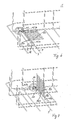
- Figure 5 shows a second preferred embodiment at least one pivotable in the crockery basket 1 of a dishwasher arranged plate rake 8 being simultaneously Non-use, use, stress and rest position shown on four different plate rakes 8a-d are. It is shown as an example that the plate rake 8a-d do not extend over the entire width of the crockery basket 1 must, but rather across the width of the crockery basket 1 several plate rakes 8a-d, in the exemplary embodiment shown two plate rakes 8a and 8d or 8c and 8b can be arranged. On one end piece of all base bars 9a-d the stop G 11 is bent over, this only for the plate rake 8c and 8a in stress and non-use position is visible.
- the end piece of the base rods 9a-d is a crank each 18 cranked and a pressing spring element 15a acts on the crank 18.
- the receiving elements 16a and 15b complete the storage as in the first embodiment of the base rod 9a-d and do not work through it aligned arrangement as well as alternating arrangement of pressing and holding spring or receiving elements and thus the pressure points on every single curved base rod 9a-d generating tension, the tension of the spring element 15a is larger than that in this pressure point acting tension on the base rod.
- each of the base bars 9a-d has a maximum stress in the stress position and an automatic snapping of the base bar 9b and thus the plate rake 8b from a reduced voltage Use position is prevented by a stop G 11 to to enable a wash-free setting of wash ware.
- the spring or receiving elements 15a, 16a, 15b of the type holding-pressing realized 15a and 15b realize a Fixed bearing in the X and Y directions
- 16a is a semi-loose bearing realized.
- the interaction of the bearings can be: Pressure points on the base bar, stress relationships of the contact element and directions from the first Embodiment are transferred.
- the guy holding, holding, holding is also feasible, the crank 18th would have to be arranged in the middle.
- Figure 6 shows a section of Figure 5, with others Details of the crockery basket 1 for better illustration are omitted.
- the plate rake 8a is in Non-use. Through the cross strut 7, its further movement to the rest position 8d, cf. Fig. 9 prevented.
- the crank 18 is to the receiving element acting on it 15a in a position in which the voltage maximum has not yet been reached.
- As a bearing for the base bar 9a are only the two outer pressing bearing elements 15a and 15b visible since a longitudinal strut 6 (in FIG. 5 visible), which represents a holding receiving element 16a, 6 has been omitted for the sake of clarity.
- the G 11 stop is not yet in operation.
- FIG. 7 again makes it clear that three bearing elements 15a, 16a, 15b are at least necessary, which are of the push-hold-push type in order to snap the plate rake from a stress position 8c into a use position 8b or non-use position 8a enable.
- FIG. 7 shows a detail from FIG. 5 with a plate rake 8b in the position of use.
- the stop G 11 prevents further movement of the plate rake 8b to the left and supports the plate rake 8b on the axis 5 of the wheel attachment or a rod of the side wall 3.
- the spring or receiving elements 15a, 16a, 15b are designed as bearing elements.
- the plate rake 8b has already passed its maximum tension when swiveling out of its non-use position 8a (shown in FIG. 6) through its stress position 8c (shown in FIG. 8) into its use position 8b (shown in FIG. 7) and is determined without play in the position of use, the Disc rake 8b and in particular its base rod 9b are still in a stress-reduced state with regard to the stress situation.
- a further stop Z 17 can be seen in FIG. 7, which is arranged in the vicinity of the receiving element 15b on the base rod 8b, this being shorter than the spikes 10, but oriented like this. The stop Z 17 prevents movement of the base bar 8, 8a-d in the direction of the free coordinate axis Z, ie through the side walls 3 of the crockery basket 1.
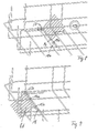
- Figure 8 shows a section of Figure 5 with the plate rake 9c in the stress position at approx. 45 °, the selection the stress situation mainly from the angular position of the receiving element 15a and the position of the upper Crank piece 18a depends in the receiving element 15a.
- the base rod 9c and thus the plate rake 8c have a position not representable the state of maximum tension and snapped automatically in its use or 8b position 8a in order to assume a reduced-voltage state. Assuming a dead state 8d is prevented by the stops G 11 and N.
- FIG. 5 A section according to FIG. 5 is shown in FIG the plate rake 9d exemplarily in a non-ingestible rest position is shown.
- the G 11 stop was in the Illustration omitted, as well as all others as stops N-acting cross struts 7.
- the tension-free rest position lies the load situation with maximum stress at approx. 225 ° opposite and is thus compared to this shown in Figure 8 Stress position rotated by 180 °. It is visible that the crank 18 is in contact with the receiving element in the rest position 15a loses. As a result, the base rod 8d only the two other mounting elements reduce the tension 16a and 15b.
- Figure 11 is the principle of operation of a second embodiment i.a. 5 to 9 shown.
- the base bar is not exactly in line arranged receiving and / or spring elements clamped.
- the arrows represent those that act alternately on the base rod Pressure points.
Landscapes
- Washing And Drying Of Tableware (AREA)
Abstract
Description
- Figur 1
- einen Ausschnitt eines Geschirrkorbes, an dem bekannte, für die Erfindung jedoch unwesentliche Bestandteile, zwecks besserer Übersicht weggelassen worden sind, mit einem als Tellerrechen ausgebildeten Anlageelement in Nichtgebrauchslage;
- Figur 2
- eine Darstellung des Geschirrkorbes nach Figur 1 mit einem Tellerrechen in Gebrauchslage;
- Figur 3
- einen Geschirrkorb nach Figur 1 mit einem Tellerrechen in Beanspruchungslage;
- Figur 4
- einen Geschirrkorb nach Figur 1 mit einem Tellerrechen in angedeuteter jedoch nicht einnehmbarer Ruhelage;
- Figur 5
- mehrere Tellerrechen mit jeweils an einem Ende angekröpfter Kurbel, auf die ein Federelement wirkt, wobei die Positionen der Figuren 1 bis 4 des Tellerrechens in einer Darstellung gezeigt werden;
- Figur 6
- einen Ausschnitt aus Figur 5, wobei weitere Bestandteile des Geschirrkorbes zwecks besserer Übersicht weggelassen worden sind, mit dem Tellerrechen in Nichtgebrauchslage;
- Figur 7
- einen Ausschnitt aus Figur 5 mit einem Tellerrechen in Gebrauchslage;
- Figur 8
- eine Darstellung nach Figur 5 mit einem Tellerrechen in Beanspruchungslage;
- Figur 9
- einen Tellerrechen nach Figur 5 in exemplarisch gezeigter, jedoch nicht einnehmbarer Ruhelage;
- Figur 10
- ein Schema eines Funktionsprinzipes einer ersten Ausführungsform;
- Figur 11
- ein Schema eines Funktionsprinzipes einer zweiten Ausführungsform.
Figur 7 zeigt einen Ausschnitt aus Figur 5 mit einem Tellerrechen 8b in Gebrauchslage. Der Anschlag G 11 verhindert eine Weiterbewegung des Tellerrechens 8b nach links und stützt den Tellerrechen 8b auf der Achse 5 der Räderbefestigung bzw. einem Stab der Seitenwand 3 ab. Als Lagerelemente sind wie oben genannt die Feder- bzw. Aufnahmeelemente 15a, 16a, 15b ausgebildet. Der Tellerrechen 8b hat beim Verschwenken aus seiner Nichtgebrauchslage 8a (gezeigt in Figur 6) durch seine Beanspruchungslage 8c (gezeigt in Fig. 8) in seine Gebrauchslage 8b (gezeigt in Figur 7) sein Spannungsmaximum bereits durchschritten und ist in Gebrauchslage spielfrei festgestellt, wobei der Tellerrechen 8b und insbesondere sein Basisstab 9b sich weiterhin in einem bezüglich der Beanspruchungslage spannungsreduziertem Zustand befindet. Es ist in Figur 7 ein weiterer Anschlag Z 17 sichtbar, der in Nachbarschaft des Aufnahmeelementes 15b am Basisstab 8b angeordnet, wobei dieser kürzer als die Stacheln 10 ist, jedoch wie diese ausgerichtet ist. Der Anschlag Z 17 verhindert eine Bewegung des Basisstabes 8,8a-d in Richtung der freien Koordinatenachse Z, d.h. durch die Seitenwände 3 des Geschirrkorbes 1 hindurch.
- 1
- Geschirrkorb
- 2
- Geschirrkorbboden
- 3
- Seitenwand
- 4
- Laufrad
- 5
- Achse der Laufräder 4
- 6
- Längsstreben von 2
- 7
- Querstreben von 2
- 8
- Tellerrechen
- 8a
- Tellerrechen in Nichtgebrauchslage
- 8b
- Tellerrechen in Gebrauchslage
- 8c
- Tellerrechen in Beanspruchungslage
- 8d
- Tellerrechen in Ruhelage
- 9
- Basisstab
- 9a
- Basisstab in Nichtgebrauchslage
- 9b
- Basisstab in Gebrauchslage
- 9c
- Basisstab in Beanspruchungslage
- 9d
- Basisstab in Ruhelage
- 10
- Stacheln
- 11
- Anschlag G
- 12
- Koordinatensystem
- 13a
- Aufnahmeelement (haltend)
- 13b
- Aufnahmeelement (haltend)
- 13c
- Aufnahmeelement (haltend)
- 14a
- Aufnahmeelement (drückend)
- 14b
- Aufnahmeelement (drückend)
- 15a
- Aufnahmeelement (drückend)
- 15b
- Aufnahmeelement (drückend)
- 16a
- Aufnahmeelement (haltend)
- 17
- Anschlag Z
- 18
- Kurbel
- 18a
- Oberes Kurbelstück
- 19
- Drahtstück
Claims (23)
- Geschirrkorb (1) einer Geschirrspülmaschine, der mindestens ein verschwenkbares Anlageelement, welches zum Abstützen von in den Geschirrkorb eingestelltem Spülgut dient und welcher vorzugsweise als Tellerrechen (8) ausgebildet ist, wobei das Anlageelement (8) einen Basisstab (9) und zumindest einen Anlagestab (10) umfasst, wobei ferner das Anlageelement um eine Achse aus einer Nichtgebrauchslage (8a) in eine wenigstens annähernd vertikale Gebrauchslage (8b) verschwenkbar ist, dadurch gekennzeichnet, dass der Basisstab (9) als Federelement ausgebildet ist und/oder auf das Anlageelement (8) zumindest ein Federelement derart wirkt, dass das Anlageelement in Gebrauchslage (8b) gespannt ist, und dass mindestens ein Anschlag G (11) vorgesehen ist, der verhindert, dass das Anlageelement aus der Gebrauchslage (8b) wegstrebt.
- Geschirrkorb (1) einer Geschirrspülmaschine nach Anspruch 1, dadurch gekennzeichnet, dass das Anlageelement in Gebrauchslage (8b) nahezu spielfrei positioniert ist.
- Geschirrkorb (1) einer Geschirrspülmaschine nach Anspruch 1 oder 2, dadurch gekennzeichnet, dass die auf das Anlageelement wirkende Spannung in Gebrauchslage und Nichtgebrauchslage(8b) geringer als seine Spannung in einer Beanspruchungslage (8c) ist, in welcher die Spannung des Anlageelementes ein Maximum aufweist.
- Geschirrkorb (1) einer Geschirrspülmaschine nach Anspruch 3, dadurch gekennzeichnet, dass beim Verschwenken des Anlageelementes (8) eine selbsttätige Bewegung aus seiner Beanspruchungslage (8c) über seine Gebrauchslage (8b) in eine spannungsreduzierte oder eine spannungslose Ruhelage (8d) durch einen Anschlag G (11)und aus seiner Beanspruchungslage (8c) in eine spannungsreduzierte oder spannungslose Ruhelage (8d) durch einen Anschlag N verhindert ist, wobei der Anschlag N als Geschirrkorbboden (2) oder Achse (5) der Räder (4) oder Draht der Seitenwände (3) ausgebildet ist.
- Geschirrkorb (1) einer Geschirrspülmaschine nach einem der Ansprüche 1 bis 4, dadurch gekennzeichnet, dass die Spannung des Anlageelementes (8,8a-d) durch Aufnahme-elemente (13a-c, 14a-c, 15b, 16a) hauptsächlich auf den Basisstab (9,9a-d) oder auf die Federelemente (15a) ausgeübt wird.
- Geschirrkorb (1) einer Geschirrspülmaschine nach einem der Ansprüche 1 bis 5, dadurch gekennzeichnet, dass der Basisstab (9) zumindest in einem Endstück gebogen ist.
- Geschirrkorb(1)einer Geschirrspülmaschine nach Anspruch 6, dadurch gekennzeichnet, dass der Basisstab (9) vorwiegend symmetrisch und/oder in seinen beiden Basisstab-Endstücken gebogen ist.
- Geschirrkorb (1) einer Geschirrspülmaschine nach einem der Ansprüche 6 oder 7, dadurch gekennzeichnet, dass ein Endstück des Basisstabes (9) als Anschlag G (11) umgebogen ist, der das Anlageelement (8) in Gebrauchslage (8b) hält und gegen zumindest eine Längs- oder Querstrebe (6,7) des Geschirrkorbbodens (2) oder der Seitenwände (3) oder zumindest eine Achse (5) der Räder (4) oder andere Elemente des Geschirrkorbes (1) anschlägt, oder der Anschlag G (11) separat am Geschirrkorb (1) angeordnet ist und zumindest ein Element (9,10) des Anlageelementes (8) gegen diesen anschlägt.
- Geschirrkorb (1) einer Geschirrspülmaschine nach zumindest einem der Ansprüche 1 bis 8, dadurch gekennzeichnet, dass der Basisstab (9) nicht gerade und vorgespannt ist.
- Geschirrkorb (1) einer Geschirrspülmaschine nach zumindest einem der Ansprüche 3 bis 9, dadurch gekennzeichnet, dass insgesamt mindestens drei nicht fluchtende Aufnahmeelemente (13a-c, 14a-c, 15b, 16a) und/oder Federelemente (15a) vorgesehen sind, die den Basisstab (9) am Geschirrkorb (1) lagern und für den Basisstab und/oder das bzw. die Federelemente (15a) eine Beanspruchungslage (9c) festlegen.
- Geschirrkorb (1) einer Geschirrspülmaschine nach Anspruch 10, dadurch gekennzeichnet, dass der Winkel des Anlageelementes zwischen Gebrauchslage (8b) und Beanspruchungslage (8c) kleiner oder gleich dem Winkel zwischen Nichtgebrauchslage (8a) und Beanspruchungslage (8c) ist.
- Geschirrkorb (1) einer Geschirrspülmaschine nach zumindest einem der Ansprüche 5 bis 11, dadurch gekennzeichnet, dass von den einander benachbart angeordneten Aufnahme- (13a, 14a, 13b bzw. 14b, 13c, 14c) und/oder Federelementen (15a, 16a, 15b) jeweils abwechselnd eines den Basisstab (9) unterstützend hält während das andere auf diesen drückt.
- Geschirrkorb (1) einer Geschirrspülmaschine nach Anspruch 12, dadurch gekennzeichnet, dass drei vorgesehene Aufnahmeelemente und/oder Federelemente aus drei festen Lagern (13a, 14a, 13b bzw. 14b, 13c, 14c) oder einem halblosen Lager und zwei festen Lager (15a, 16a, 15b) bestehen, wobei das Festlager zumindest hinsichtlich einer Orientierung jeweils der X- und Y-Koordinate als festlagernd wirkt, während das halblose Lager zumindest in einer Orientierung einer dieser Koordinatenachsen fest ist und beide Lagerarten in einer dritten Koordinatenachse Z, welche die Verschwenkachse des Anlageelementes bildet, frei sind .
- Geschirrkorb einer Geschirrspülmaschine nach Anspruch 13, dadurch gekennzeichnet, dass zumindest ein Festlager derart ausgebildet wird, dass eine muldenförmige Ausbildung im Geschirrkorbboden (2) den Basisstab (9) aufnimmt und durch einen angeordneten Niederhalter ein Festlager für den Basisstab in X- und Y-Koordinate realisiert ist.
- Geschirrkorb (1) einer Geschirrspülmaschine nach zumindest einem der Ansprüche 5 bis 14, dadurch gekennzeichnet, dass zumindest ein auf den Basisstab (9) wirkendes Federelement als Zunge ausgeführt ist und/oder an einem Element des Geschirrkorbes mehrere Aufnahmeelemente (13a,14b) angeordnet sind, die auf verschiedene Basisstäbe (9) wirken.
- Geschirrkorb (1) einer Geschirrspülmaschine nach zumindest einem der vorstehenden Ansprüche, dadurch gekennzeichnet, dass an einem Endstück des Basisstabes (9) eine Kurbel (18) gekröpft oder gebogen ist.
- Geschirrkorb (1) einer Geschirrspülmaschine nach zumindest einem der vorstehenden Ansprüche, dadurch gekennzeichnet, dass durch manuellen Eingriff das Anlageelement (8) aus seiner Nichtgebrauchslage (8a) in die Gebrauchslage (8b) und umgekehrt verschnappbar ist.
- Geschirrkorb (1) einer Geschirrspülmaschine nach zumindest einem der vorstehenden Ansprüche, dadurch gekennzeichnet, dass das Anlageelement in Gebrauchslage (8b) in zumindest ein angeordnetes Fixierelement schnappt, welches eine muldenförmige Einbuchtung aufweist.
- Geschirrkorb (1) einer Geschirrspülmaschine nach Anspruch 18, dadurch gekennzeichnet, dass die muldenförmige Vertiefung in einem der vorhandenen Elemente integriert ist oder separat mit dem Fixierelement angeordnet ist.
- Geschirrkorb (1) einer Geschirrspülmaschine nach zumindest einem der vorstehenden Ansprüche, dadurch gekennzeichnet, dass zumindest ein weiterer Anschlag Z (17) am Geschirrkorb (1) oder Basisstab (9) angeordnet ist, welcher das seitliche Herausrutschen des Basisstabes (9) in seiner Achsenrichtung aus dem Geschirrkorb (1) verhindert und/oder der den Basisstab (9) zumindest in einem weiteren Punkt abstützt.
- Geschirrkorb (1) einer Geschirrspülmaschine nach Anspruch 20, dadurch gekennzeichnet, dass der Anschlag Z zusätzlich als Befestigungsvorrichtung zum Eintauchen des Drahtgeflechtes in ein Kunststoffgemisch zwecks Ausbildung eines Kunststoffüberzuges dient.
- Geschirrkorb (1) einer Geschirrspülmaschine nach zumindest einem der vorstehenden Ansprüche, dadurch gekennzeichnet, dass die Festlager des Basisstabes (9) als Klammern oder Ausformungen in einem Element (19) des Geschirrkorbes (2) ausgebildet sind.
- Geschirrkorb (1) einer Geschirrspülmaschine nach einem der vorstehenden Ansprüche, dadurch gekennzeichnet, dass die Aufnahmeelemente (13a, 14a, 13b, 14b, 13c, 14c, 16a, 16b) des Basisstabes (9) und/oder Federelemente (15a) und/oder Fixierelemente und/oder Anschläge N, G (11), Z (17) aus Kunststoff oder dem gleichen Material wie der Geschirrkorb bestehen.
Applications Claiming Priority (2)
| Application Number | Priority Date | Filing Date | Title |
|---|---|---|---|
| DE10204692 | 2002-02-06 | ||
| DE10204692A DE10204692B4 (de) | 2002-02-06 | 2002-02-06 | Verschwenkbar im Geschirrkorb einer Geschirrspülmaschine angeordnetes Anlageelement |
Publications (3)
| Publication Number | Publication Date |
|---|---|
| EP1336370A2 true EP1336370A2 (de) | 2003-08-20 |
| EP1336370A3 EP1336370A3 (de) | 2005-01-12 |
| EP1336370B1 EP1336370B1 (de) | 2006-05-24 |
Family
ID=27588369
Family Applications (1)
| Application Number | Title | Priority Date | Filing Date |
|---|---|---|---|
| EP03001145A Expired - Lifetime EP1336370B1 (de) | 2002-02-06 | 2003-01-21 | Verschwenkbar im Geschirrkorb einer Geschirrspülmaschine angeordnetes Anlageelement |
Country Status (4)
| Country | Link |
|---|---|
| EP (1) | EP1336370B1 (de) |
| AT (1) | ATE326898T1 (de) |
| DE (2) | DE10204692B4 (de) |
| ES (1) | ES2266650T3 (de) |
Cited By (4)
| Publication number | Priority date | Publication date | Assignee | Title |
|---|---|---|---|---|
| WO2007045559A1 (de) * | 2005-10-19 | 2007-04-26 | BSH Bosch und Siemens Hausgeräte GmbH | Geschirrkorb zur aufnahme von geschirrteilen, insbesondere für eine geschirrspülmaschine, sowie geschirrspülmaschine mit einem geschirrkorb |
| ITTO20110744A1 (it) * | 2011-08-05 | 2013-02-06 | Indesit Co Spa | Cestello per macchina lavastoviglie comprendente dei supporti ripiegabili/basculanti e almeno un elemento d'arresto separabile dal cestello |
| ITTO20110742A1 (it) * | 2011-08-05 | 2013-02-06 | Indesit Co Spa | Cestello per macchina lavastoviglie comprendente dei supporti basculanti e ripiegabili che non tensionano i fili del cestello |
| CN107638156A (zh) * | 2017-10-31 | 2018-01-30 | 科普瑞(天津)厨房设备有限公司 | 洗碗机用碗筷放置架 |
Families Citing this family (5)
| Publication number | Priority date | Publication date | Assignee | Title |
|---|---|---|---|---|
| DE102004035726A1 (de) | 2004-07-23 | 2006-03-16 | BSH Bosch und Siemens Hausgeräte GmbH | Geschirrkorb zur variablen Aufnahme von Geschirrteilen |
| ES2291801T3 (es) * | 2004-12-01 | 2008-03-01 | Electrolux Home Products Corporation N.V. | Cesto portavajilla con dispositivo de retencion de vajilla basculable. |
| DE102008015713A1 (de) | 2008-03-26 | 2009-10-01 | BSH Bosch und Siemens Hausgeräte GmbH | Geschirrkorb und Geschirrspülmaschine |
| DE102008015714A1 (de) | 2008-03-26 | 2009-10-01 | BSH Bosch und Siemens Hausgeräte GmbH | Geschirrkorb und Geschirrspülmaschine |
| EP2215956B1 (de) | 2009-02-10 | 2020-05-27 | Electrolux Home Products Corporation N.V. | Anpassbare Gestellanordnung für einen Spülmaschinenkorb |
Family Cites Families (8)
| Publication number | Priority date | Publication date | Assignee | Title |
|---|---|---|---|---|
| US3612285A (en) * | 1970-02-16 | 1971-10-12 | Whirlpool Co | Dishwasher dishrack |
| DE3022484A1 (de) * | 1980-06-14 | 1982-01-07 | Euro Hausgeräte GmbH, 6680 Neunkirchen | Vorrichtung fuer geschirrkoerbe von haushaltgeschirrspuelmaschinen |
| IT235015Y1 (it) * | 1994-04-01 | 2000-03-31 | Zanussi Elettrodomestici | Cesto per lavastoviglie con setto mobile |
| IT1284434B1 (it) * | 1996-03-27 | 1998-05-21 | Smeg Spa | Cestello per lavastoviglie con supporti reggipiatti ribaltabili |
| IT1289748B1 (it) * | 1996-12-13 | 1998-10-16 | Merloni Elettrodomestici Spa | Cestello per macchina lavastoviglie e relativo metodo di produzione |
| WO2000049935A1 (en) * | 1999-02-22 | 2000-08-31 | Arçeli̇k A.Ş. | Dishwashing machine basket with foldable dish holder racks |
| DE29921601U1 (de) * | 1999-12-08 | 2000-02-17 | Whirlpool Corp., Benton Harbor, Mich. | Geschirrkorb für Geschirrspülmaschinen |
| DE10051935A1 (de) * | 2000-10-19 | 2002-05-02 | Bsh Bosch Siemens Hausgeraete | Geschirrkorb zur Aufnahme von Geschirrteilen und Geschirrspülmaschine |
-
2002
- 2002-02-06 DE DE10204692A patent/DE10204692B4/de not_active Expired - Fee Related
-
2003
- 2003-01-21 EP EP03001145A patent/EP1336370B1/de not_active Expired - Lifetime
- 2003-01-21 ES ES03001145T patent/ES2266650T3/es not_active Expired - Lifetime
- 2003-01-21 DE DE50303415T patent/DE50303415D1/de not_active Expired - Fee Related
- 2003-01-21 AT AT03001145T patent/ATE326898T1/de not_active IP Right Cessation
Cited By (7)
| Publication number | Priority date | Publication date | Assignee | Title |
|---|---|---|---|---|
| WO2007045559A1 (de) * | 2005-10-19 | 2007-04-26 | BSH Bosch und Siemens Hausgeräte GmbH | Geschirrkorb zur aufnahme von geschirrteilen, insbesondere für eine geschirrspülmaschine, sowie geschirrspülmaschine mit einem geschirrkorb |
| ITTO20110744A1 (it) * | 2011-08-05 | 2013-02-06 | Indesit Co Spa | Cestello per macchina lavastoviglie comprendente dei supporti ripiegabili/basculanti e almeno un elemento d'arresto separabile dal cestello |
| ITTO20110742A1 (it) * | 2011-08-05 | 2013-02-06 | Indesit Co Spa | Cestello per macchina lavastoviglie comprendente dei supporti basculanti e ripiegabili che non tensionano i fili del cestello |
| EP2554095A1 (de) * | 2011-08-05 | 2013-02-06 | Indesit Company S.p.A. | Geschirrkorb einer Geschirrspülmaschine, mit verschwenkbare, zusammenklappbare Anlageelemente |
| EP2554096A3 (de) * | 2011-08-05 | 2013-08-28 | Indesit Company S.p.A. | Korb für Geschirrspülmaschinen mit schwenkbare Stützelemente und zumindest einem abnehmbaren Halteelement |
| EP3045099A3 (de) * | 2011-08-05 | 2016-10-19 | Indesit Company S.p.A. | Geschirrkorb mit falt-/kippbaren stützen |
| CN107638156A (zh) * | 2017-10-31 | 2018-01-30 | 科普瑞(天津)厨房设备有限公司 | 洗碗机用碗筷放置架 |
Also Published As
| Publication number | Publication date |
|---|---|
| DE10204692A1 (de) | 2003-08-14 |
| DE50303415D1 (de) | 2006-06-29 |
| ATE326898T1 (de) | 2006-06-15 |
| DE10204692B4 (de) | 2004-02-26 |
| EP1336370B1 (de) | 2006-05-24 |
| EP1336370A3 (de) | 2005-01-12 |
| ES2266650T3 (es) | 2007-03-01 |
Similar Documents
| Publication | Publication Date | Title |
|---|---|---|
| EP1829443B1 (de) | Obstadaptivpflücker mit verstellbarem Pflückrechen und gekammertem Auffangbeutel | |
| EP2015369A2 (de) | Lagergestell zum Abstütz von flächigen Solarpaneelen | |
| DE3832996A1 (de) | Dreschkorb fuer maehdrescher | |
| EP1336370B1 (de) | Verschwenkbar im Geschirrkorb einer Geschirrspülmaschine angeordnetes Anlageelement | |
| DE212007000080U1 (de) | Hubsäule für Krankenhaus- oder Pflegebetten | |
| DE1941854B2 (de) | Stellage zur Lagerung von Stangenmaterial | |
| DE60035400T2 (de) | Geschirrkorb für eine Geschirrspülmaschine | |
| EP0457034A1 (de) | Wäscheständer mit Trocknungsrost | |
| DE69807414T2 (de) | Ständer zum Auflegen von Angelruten | |
| DE102008023097B4 (de) | Tor für ein Ballspiel | |
| DE2345494A1 (de) | Sammelblech-anordnung bei einem kolbenpflueck-vorsatzgeraet | |
| DE2322732B2 (de) | Stange als konstruktionsteil von sporteinrichtungen, insbesondere als torbalken oder als tragsaeule zum aufspannen von volleyball- und tennisnetzen oder zum anbringen von basketballkoerben | |
| AT386530B (de) | Ballaufhebevorrichtung, insbesondere fuer tennisbaelle | |
| CH670200A5 (de) | ||
| DE102020004880A1 (de) | Pfosten für Spalieranlagen | |
| EP1080637A1 (de) | Vogelfutterhaus | |
| EP0812531A1 (de) | Landmaschine mit einschwenkbarer grosser Arbeitsbreite | |
| DE3913821C1 (de) | ||
| DE29608247U1 (de) | Obstpflücker für die Ernte unterschiedlich großer Früchte | |
| DE69104633T2 (de) | Erntehebegerät. | |
| DE8905114U1 (de) | Rankgitter | |
| DE202025102378U1 (de) | Rankgerüst | |
| DE9217506U1 (de) | Zinken für einen Ackerstriegel | |
| WO2025040592A1 (de) | Trampolingestell | |
| DE20205045U1 (de) | Zusammenlegbares Angelgestell zur Aufnahme mehrerer Angelruten |
Legal Events
| Date | Code | Title | Description |
|---|---|---|---|
| PUAI | Public reference made under article 153(3) epc to a published international application that has entered the european phase |
Free format text: ORIGINAL CODE: 0009012 |
|
| AK | Designated contracting states |
Designated state(s): AT BE BG CH CY CZ DE DK EE ES FI FR GB GR HU IE IT LI LU MC NL PT SE SI SK TR |
|
| AX | Request for extension of the european patent |
Extension state: AL LT LV MK RO |
|
| PUAL | Search report despatched |
Free format text: ORIGINAL CODE: 0009013 |
|
| AK | Designated contracting states |
Kind code of ref document: A3 Designated state(s): AT BE BG CH CY CZ DE DK EE ES FI FR GB GR HU IE IT LI LU MC NL PT SE SI SK TR |
|
| AX | Request for extension of the european patent |
Extension state: AL LT LV MK RO |
|
| 17P | Request for examination filed |
Effective date: 20050112 |
|
| 17Q | First examination report despatched |
Effective date: 20050518 |
|
| AKX | Designation fees paid |
Designated state(s): DE ES FR IT SE TR |
|
| RBV | Designated contracting states (corrected) |
Designated state(s): DE ES FR GB IT SE TR |
|
| GRAP | Despatch of communication of intention to grant a patent |
Free format text: ORIGINAL CODE: EPIDOSNIGR1 |
|
| RBV | Designated contracting states (corrected) |
Designated state(s): AT BE BG CH CY CZ DE DK EE ES FI FR GB GR HU IE IT LI LU MC NL PT SE SI SK TR |
|
| GRAS | Grant fee paid |
Free format text: ORIGINAL CODE: EPIDOSNIGR3 |
|
| GRAA | (expected) grant |
Free format text: ORIGINAL CODE: 0009210 |
|
| AK | Designated contracting states |
Kind code of ref document: B1 Designated state(s): AT BE BG CH CY CZ DE DK EE ES FI FR GB GR HU IE IT LI LU MC NL PT SE SI SK TR |
|
| PG25 | Lapsed in a contracting state [announced via postgrant information from national office to epo] |
Ref country code: IT Free format text: LAPSE BECAUSE OF FAILURE TO SUBMIT A TRANSLATION OF THE DESCRIPTION OR TO PAY THE FEE WITHIN THE PRESCRIBED TIME-LIMIT;WARNING: LAPSES OF ITALIAN PATENTS WITH EFFECTIVE DATE BEFORE 2007 MAY HAVE OCCURRED AT ANY TIME BEFORE 2007. THE CORRECT EFFECTIVE DATE MAY BE DIFFERENT FROM THE ONE RECORDED. Effective date: 20060524 Ref country code: CZ Free format text: LAPSE BECAUSE OF FAILURE TO SUBMIT A TRANSLATION OF THE DESCRIPTION OR TO PAY THE FEE WITHIN THE PRESCRIBED TIME-LIMIT Effective date: 20060524 Ref country code: SI Free format text: LAPSE BECAUSE OF FAILURE TO SUBMIT A TRANSLATION OF THE DESCRIPTION OR TO PAY THE FEE WITHIN THE PRESCRIBED TIME-LIMIT Effective date: 20060524 Ref country code: IE Free format text: LAPSE BECAUSE OF FAILURE TO SUBMIT A TRANSLATION OF THE DESCRIPTION OR TO PAY THE FEE WITHIN THE PRESCRIBED TIME-LIMIT Effective date: 20060524 Ref country code: FI Free format text: LAPSE BECAUSE OF FAILURE TO SUBMIT A TRANSLATION OF THE DESCRIPTION OR TO PAY THE FEE WITHIN THE PRESCRIBED TIME-LIMIT Effective date: 20060524 Ref country code: SK Free format text: LAPSE BECAUSE OF FAILURE TO SUBMIT A TRANSLATION OF THE DESCRIPTION OR TO PAY THE FEE WITHIN THE PRESCRIBED TIME-LIMIT Effective date: 20060524 Ref country code: NL Free format text: LAPSE BECAUSE OF FAILURE TO SUBMIT A TRANSLATION OF THE DESCRIPTION OR TO PAY THE FEE WITHIN THE PRESCRIBED TIME-LIMIT Effective date: 20060524 |
|
| REG | Reference to a national code |
Ref country code: GB Ref legal event code: FG4D Free format text: NOT ENGLISH |
|
| REG | Reference to a national code |
Ref country code: CH Ref legal event code: EP |
|
| REG | Reference to a national code |
Ref country code: IE Ref legal event code: FG4D Free format text: LANGUAGE OF EP DOCUMENT: GERMAN |
|
| REF | Corresponds to: |
Ref document number: 50303415 Country of ref document: DE Date of ref document: 20060629 Kind code of ref document: P |
|
| PG25 | Lapsed in a contracting state [announced via postgrant information from national office to epo] |
Ref country code: DK Free format text: LAPSE BECAUSE OF FAILURE TO SUBMIT A TRANSLATION OF THE DESCRIPTION OR TO PAY THE FEE WITHIN THE PRESCRIBED TIME-LIMIT Effective date: 20060824 |
|
| REG | Reference to a national code |
Ref country code: SE Ref legal event code: TRGR |
|
| PG25 | Lapsed in a contracting state [announced via postgrant information from national office to epo] |
Ref country code: PT Free format text: LAPSE BECAUSE OF FAILURE TO SUBMIT A TRANSLATION OF THE DESCRIPTION OR TO PAY THE FEE WITHIN THE PRESCRIBED TIME-LIMIT Effective date: 20061024 |
|
| GBT | Gb: translation of ep patent filed (gb section 77(6)(a)/1977) |
Effective date: 20060928 |
|
| NLV1 | Nl: lapsed or annulled due to failure to fulfill the requirements of art. 29p and 29m of the patents act | ||
| REG | Reference to a national code |
Ref country code: IE Ref legal event code: FD4D |
|
| ET | Fr: translation filed | ||
| PG25 | Lapsed in a contracting state [announced via postgrant information from national office to epo] |
Ref country code: LI Free format text: LAPSE BECAUSE OF NON-PAYMENT OF DUE FEES Effective date: 20070131 Ref country code: MC Free format text: LAPSE BECAUSE OF NON-PAYMENT OF DUE FEES Effective date: 20070131 Ref country code: CH Free format text: LAPSE BECAUSE OF NON-PAYMENT OF DUE FEES Effective date: 20070131 |
|
| REG | Reference to a national code |
Ref country code: ES Ref legal event code: FG2A Ref document number: 2266650 Country of ref document: ES Kind code of ref document: T3 |
|
| PLBE | No opposition filed within time limit |
Free format text: ORIGINAL CODE: 0009261 |
|
| STAA | Information on the status of an ep patent application or granted ep patent |
Free format text: STATUS: NO OPPOSITION FILED WITHIN TIME LIMIT |
|
| 26N | No opposition filed |
Effective date: 20070227 |
|
| REG | Reference to a national code |
Ref country code: CH Ref legal event code: PL |
|
| BERE | Be: lapsed |
Owner name: ELECTROLUX HOME PRODUCTS CORPORATION N.V. Effective date: 20070131 |
|
| PG25 | Lapsed in a contracting state [announced via postgrant information from national office to epo] |
Ref country code: BE Free format text: LAPSE BECAUSE OF NON-PAYMENT OF DUE FEES Effective date: 20070131 |
|
| PG25 | Lapsed in a contracting state [announced via postgrant information from national office to epo] |
Ref country code: GR Free format text: LAPSE BECAUSE OF FAILURE TO SUBMIT A TRANSLATION OF THE DESCRIPTION OR TO PAY THE FEE WITHIN THE PRESCRIBED TIME-LIMIT Effective date: 20060825 |
|
| PGFP | Annual fee paid to national office [announced via postgrant information from national office to epo] |
Ref country code: DE Payment date: 20080111 Year of fee payment: 6 |
|
| PG25 | Lapsed in a contracting state [announced via postgrant information from national office to epo] |
Ref country code: BG Free format text: LAPSE BECAUSE OF FAILURE TO SUBMIT A TRANSLATION OF THE DESCRIPTION OR TO PAY THE FEE WITHIN THE PRESCRIBED TIME-LIMIT Effective date: 20060824 Ref country code: AT Free format text: LAPSE BECAUSE OF NON-PAYMENT OF DUE FEES Effective date: 20070121 |
|
| PG25 | Lapsed in a contracting state [announced via postgrant information from national office to epo] |
Ref country code: EE Free format text: LAPSE BECAUSE OF FAILURE TO SUBMIT A TRANSLATION OF THE DESCRIPTION OR TO PAY THE FEE WITHIN THE PRESCRIBED TIME-LIMIT Effective date: 20060524 |
|
| PGFP | Annual fee paid to national office [announced via postgrant information from national office to epo] |
Ref country code: ES Payment date: 20090122 Year of fee payment: 7 |
|
| PG25 | Lapsed in a contracting state [announced via postgrant information from national office to epo] |
Ref country code: LU Free format text: LAPSE BECAUSE OF NON-PAYMENT OF DUE FEES Effective date: 20070121 Ref country code: CY Free format text: LAPSE BECAUSE OF FAILURE TO SUBMIT A TRANSLATION OF THE DESCRIPTION OR TO PAY THE FEE WITHIN THE PRESCRIBED TIME-LIMIT Effective date: 20060524 |
|
| PGFP | Annual fee paid to national office [announced via postgrant information from national office to epo] |
Ref country code: SE Payment date: 20090120 Year of fee payment: 7 |
|
| PG25 | Lapsed in a contracting state [announced via postgrant information from national office to epo] |
Ref country code: HU Free format text: LAPSE BECAUSE OF FAILURE TO SUBMIT A TRANSLATION OF THE DESCRIPTION OR TO PAY THE FEE WITHIN THE PRESCRIBED TIME-LIMIT Effective date: 20061125 |
|
| PG25 | Lapsed in a contracting state [announced via postgrant information from national office to epo] |
Ref country code: DE Free format text: LAPSE BECAUSE OF NON-PAYMENT OF DUE FEES Effective date: 20090801 |
|
| EUG | Se: european patent has lapsed | ||
| REG | Reference to a national code |
Ref country code: ES Ref legal event code: FD2A Effective date: 20110328 |
|
| PG25 | Lapsed in a contracting state [announced via postgrant information from national office to epo] |
Ref country code: ES Free format text: LAPSE BECAUSE OF NON-PAYMENT OF DUE FEES Effective date: 20110315 |
|
| PGFP | Annual fee paid to national office [announced via postgrant information from national office to epo] |
Ref country code: GB Payment date: 20110121 Year of fee payment: 9 |
|
| PG25 | Lapsed in a contracting state [announced via postgrant information from national office to epo] |
Ref country code: ES Free format text: LAPSE BECAUSE OF NON-PAYMENT OF DUE FEES Effective date: 20100122 |
|
| REG | Reference to a national code |
Ref country code: FR Ref legal event code: CA Effective date: 20120116 |
|
| PGFP | Annual fee paid to national office [announced via postgrant information from national office to epo] |
Ref country code: FR Payment date: 20120206 Year of fee payment: 10 |
|
| GBPC | Gb: european patent ceased through non-payment of renewal fee |
Effective date: 20120121 |
|
| PG25 | Lapsed in a contracting state [announced via postgrant information from national office to epo] |
Ref country code: SE Free format text: LAPSE BECAUSE OF NON-PAYMENT OF DUE FEES Effective date: 20100122 |
|
| PG25 | Lapsed in a contracting state [announced via postgrant information from national office to epo] |
Ref country code: GB Free format text: LAPSE BECAUSE OF NON-PAYMENT OF DUE FEES Effective date: 20120121 |
|
| REG | Reference to a national code |
Ref country code: FR Ref legal event code: ST Effective date: 20130930 |
|
| PG25 | Lapsed in a contracting state [announced via postgrant information from national office to epo] |
Ref country code: FR Free format text: LAPSE BECAUSE OF NON-PAYMENT OF DUE FEES Effective date: 20130131 |
|
| PGFP | Annual fee paid to national office [announced via postgrant information from national office to epo] |
Ref country code: TR Payment date: 20200117 Year of fee payment: 18 |
|
| PG25 | Lapsed in a contracting state [announced via postgrant information from national office to epo] |
Ref country code: TR Free format text: LAPSE BECAUSE OF NON-PAYMENT OF DUE FEES Effective date: 20210121 |