EP1336023B1 - Opening mechanism for the side sliding door of a motor vehicle - Google Patents
Opening mechanism for the side sliding door of a motor vehicle Download PDFInfo
- Publication number
- EP1336023B1 EP1336023B1 EP01994646A EP01994646A EP1336023B1 EP 1336023 B1 EP1336023 B1 EP 1336023B1 EP 01994646 A EP01994646 A EP 01994646A EP 01994646 A EP01994646 A EP 01994646A EP 1336023 B1 EP1336023 B1 EP 1336023B1
- Authority
- EP
- European Patent Office
- Prior art keywords
- door
- motor vehicle
- arms
- trolley
- sliding door
- Prior art date
- Legal status (The legal status is an assumption and is not a legal conclusion. Google has not performed a legal analysis and makes no representation as to the accuracy of the status listed.)
- Expired - Lifetime
Links
Images


Classifications
-
- E—FIXED CONSTRUCTIONS
- E05—LOCKS; KEYS; WINDOW OR DOOR FITTINGS; SAFES
- E05D—HINGES OR SUSPENSION DEVICES FOR DOORS, WINDOWS OR WINGS
- E05D15/00—Suspension arrangements for wings
- E05D15/06—Suspension arrangements for wings for wings sliding horizontally more or less in their own plane
- E05D15/10—Suspension arrangements for wings for wings sliding horizontally more or less in their own plane movable out of one plane into a second parallel plane
- E05D15/1005—Suspension arrangements for wings for wings sliding horizontally more or less in their own plane movable out of one plane into a second parallel plane the wing being supported on arms movable in horizontal planes
- E05D15/101—Suspension arrangements for wings for wings sliding horizontally more or less in their own plane movable out of one plane into a second parallel plane the wing being supported on arms movable in horizontal planes specially adapted for vehicles
-
- E—FIXED CONSTRUCTIONS
- E05—LOCKS; KEYS; WINDOW OR DOOR FITTINGS; SAFES
- E05D—HINGES OR SUSPENSION DEVICES FOR DOORS, WINDOWS OR WINGS
- E05D15/00—Suspension arrangements for wings
- E05D15/06—Suspension arrangements for wings for wings sliding horizontally more or less in their own plane
- E05D15/10—Suspension arrangements for wings for wings sliding horizontally more or less in their own plane movable out of one plane into a second parallel plane
- E05D2015/1026—Suspension arrangements for wings for wings sliding horizontally more or less in their own plane movable out of one plane into a second parallel plane accessories, e.g. sliding or rolling guides, latches
-
- E—FIXED CONSTRUCTIONS
- E05—LOCKS; KEYS; WINDOW OR DOOR FITTINGS; SAFES
- E05Y—INDEXING SCHEME RELATING TO HINGES OR OTHER SUSPENSION DEVICES FOR DOORS, WINDOWS OR WINGS AND DEVICES FOR MOVING WINGS INTO OPEN OR CLOSED POSITION, CHECKS FOR WINGS AND WING FITTINGS NOT OTHERWISE PROVIDED FOR, CONCERNED WITH THE FUNCTIONING OF THE WING
- E05Y2900/00—Application of doors, windows, wings or fittings thereof
- E05Y2900/50—Application of doors, windows, wings or fittings thereof for vehicles
- E05Y2900/53—Application of doors, windows, wings or fittings thereof for vehicles characterised by the type of wing
- E05Y2900/531—Doors
Definitions
- the present invention relates to a mechanism adapted to open the side sliding door of a motor vehicle and more in particular the door of a motor vehicle intended for passenger transportation.
- reference number 1 indicates a sliding door of a motor vehicle, shown in a schematic view, while reference number 2 indicates the part of the lower side member, which experts in the field call "sill".
- a wheeled trolley 3 (figures 6-8) slides according to a well known technique. Hinged to the trolley 3 at points 7 and 8 there is an end of two lower arms so that they can rotate around an axle which is basically perpendicular to the plane defined by the flat car of the bodywork.
- the other two ends of the arms 9 and 10 are rotatably engaged around a single axle with joints 12 and 13, to the lower part of the sliding door.
- the run of the trolleys 3 and 4 is limited, at the opening of the door (right side in the drawing), by a stop 17 provided with a system of engagement, for example a hook (not shown) of the trolley 3 and, at the closing of the door, by the bottom wall 19 of the space 2a, in order to get locked at the stop of the front doorlock (not shown).
- a microswitch allows to adjust both mechanically and electrically both the engagement and the release of the trolley 3 by means of the locking system 18.
- a wall 20 On the external wall of the space 2a, in front of the trolley 3, there is a wall 20 the length of which is basically equal to the length of the space 2a where the trolley 3 slides, and the front and rear ends 21 and 22 of which are curved towards the inner part of the space 2a.
- the height of the wall shall be calculated so that it will not interfere with the arms 9 and 10 when they rotate on their hinges 8 and 9.
- a bridge 23 is fixed to the lower wall of the front arm 10 by means of a axle 25.
- the diameter of the rollers 27 and 28 is such that it interacts with the external surface of the wall 20 while the arm 10 is rotating as a consequence of the opening of the sliding door.
- the same mechanism can be used in a similar elongated space, made in the upper side member of the bodywork so that it can support and guide the sliding door not only at its lower part but also at its upper part.
- the mechanism for sliding doors works as follows By means of the handle (not shown) on the door 1, the locks (in the case two locks are used, a front lock and a rear lock) are unlocked and the door makes a circular movement being supported by the arms 9 and 10 which make a basically 90 degrees rotation on the hinges 7 and 8 and reach a position which is basically perpendicular to the body side of the motor vehicle.
- the roller 27 guides the movement of the arm 10 (and consequently that of the whole door) and slides on the front curved part 21 of the wall 20 (figures 6 and 7)
- both rollers come into contact with the wall 20 thus preventing an additional rotation of the arm itself.
Description
- The present invention relates to a mechanism adapted to open the side sliding door of a motor vehicle and more in particular the door of a motor vehicle intended for passenger transportation.
- Different mechanism to open sliding side doors of commercial vehicles part of which has been adapted to transport passengers too, both as public and private/family vehicles, are already known. As far as known mechanism are concerned, the door is anchored to the bodywork and is guided not only at its lower and upper part, but also at its middle part. When this solution is adopted, designers have to provide a more or less large guide all along the side of the vehicle, so that the overall esthetical aspect of the vehicle is highly affected. Besides, known sliding doors, see as an exemple the mechanism disclosed in US-A-5921613, are mounted on vehicles the bodywork of which is provided with the central side upright, which stops both the front door and the sliding side door However, the central upright reduces the space available to reach the seats, more in particular the backseats, so that it would be better to count on a side opening completely free, that is without upright. It is to be noted that the lack of the central upright is a problem for the stopping of the front door since the stopping is to be achieved against the rear sliding door, as well as for the achievement of a mechanism that allows to open the sliding door even if the front door is closed and rests against it.
- It is an object of the present invention to provide a mechanism adapted to open a sliding door that overcomes the aforementioned drawbacks.
- Said object is achieved by means of a mechanism adapted to open the side sliding door or a motor vehicle presenting the characteristics set forth in
claim 1. - Additional characteristics and advantages will become more clear from the following description referring to the appended drawings provided as non-restrictive example and in which:
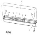
- figure 1 is a perspective view of the arm mechanisms according to the invention, housed in the lower side member of a motor vehicle and connected to a sliding door.
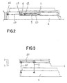
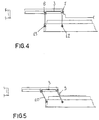
- figures 2 to 5 are schematic views of the mechanism in figure 1 with the sliding door shown in its different operational positions, from a completely closed position to the completely open position;
- figures from 6 to 10 are perspective view of an enlarged detail of the arm mechanism in figure 1 in its different operational position.
- The following description refers to a motor vehicle without central upright at its side, and in which the front profile of the side, rear, sliding door serves as stop for the weather strips of the front door. With reference to the figures,
reference number 1 indicates a sliding door of a motor vehicle, shown in a schematic view, whilereference number 2 indicates the part of the lower side member, which experts in the field call "sill". Inside thesill 2 there is an elongated space where a wheeled trolley 3 (figures 6-8) slides according to a well known technique. Hinged to thetrolley 3 atpoints arms joints trolleys 3 and 4 is limited, at the opening of the door (right side in the drawing), by astop 17 provided with a system of engagement, for example a hook (not shown) of thetrolley 3 and, at the closing of the door, by thebottom wall 19 of thespace 2a, in order to get locked at the stop of the front doorlock (not shown). A microswitch allows to adjust both mechanically and electrically both the engagement and the release of thetrolley 3 by means of the locking system 18. - On the external wall of the
space 2a, in front of thetrolley 3, there is awall 20 the length of which is basically equal to the length of thespace 2a where thetrolley 3 slides, and the front andrear ends space 2a. The height of the wall shall be calculated so that it will not interfere with thearms hinges bridge 23 is fixed to the lower wall of thefront arm 10 by means of aaxle 25. At its ends there are two small wheels orrollers rollers wall 20 while thearm 10 is rotating as a consequence of the opening of the sliding door. - Even if no detailed description is provided, the same mechanism can be used in a similar elongated space, made in the upper side member of the bodywork so that it can support and guide the sliding door not only at its lower part but also at its upper part.
- The mechanism for sliding doors according to the invention works as follows By means of the handle (not shown) on the
door 1, the locks (in the case two locks are used, a front lock and a rear lock) are unlocked and the door makes a circular movement being supported by thearms hinges roller 27 guides the movement of the arm 10 (and consequently that of the whole door) and slides on the frontcurved part 21 of the wall 20 (figures 6 and 7) When thearm 10 has reached a position which is basically perpendicular to the body side (and thearm 9 has reached the same position too), both rollers come into contact with thewall 20 thus preventing an additional rotation of the arm itself. - At this point, a further action on the handle of the door makes the
trolley 3 slide on the wheels 4 inside thespace 2a, so that thedoor 1 translates along the body side and therollers - When the
trolley 3 bumps against the stop 17 (figure 4) being engaged by it as described above, theroller 28 reaches the rearcurved part 21 of thewall 20, so that being no longer supported on said wall, allowsarm 10, and thereforearm 9, to further rotate so that thedoor 1 moves further and the door opening widens (figures 5 and 10). - The adjustment of the length of the
arms space 2a allows to determinate how much can the door move.
Claims (5)
- Mechanism adapted to open a side, rear, sliding door of a motor vehicle without central side upright, provided with front and rear arms (9, 10), a trolley (3) and guiding means (20,27,28), said arms (9,10) being adapted to make said door (1) make a pantograph movement, and being rotatably connected to a trolley (3) sliding on wheels in an elongated space (2a), made laterally in the bodywork of the motor vehicle, at the lower position; said arms (9, 10) being such that the door (1) is allowed a first pantograph movement to open and set aside the door from the body side, a second movement to translate along the body side of the motor vehicle and a third pantograph movement to achieve the maximum opening of the door; said movements being guided by means of the guiding means (20, 27, 28) connected to one of the two arms and consisting of a wall (20) fixed in use in the elongated space (2a) in front of the trolley (3), the length of which is basically equal to the length of the space (2a), wherein the wall (20) is adapted to interact with at least one of two rollers (27, 28) connected in rotation to one (10) of the arms, and in that the ends (21, 22) of said wall (20) are both curved towards the inner part of the elongated space (2a).
- Mechanism as claimed in claim 1, characterised in that the rollers are connected to the arm (10) by means of a bridge (23) that keeps them apart and the longer axis of which is basically perpendicular to the axis of said arm.
- Mechanism as claimed in claim 1, characterised in that the position of the trolley (3) is controlled by means of a stop (17) made on the edge of the spaces (2a) and provided with a system of releasable locking (18)
- Mechanism as claimed in claim 1, characterised in that the elongated space (2a) is made in the lower and upper side members of the bodywork of the motor vehicle.
- Side, rear, sliding door of a motor vehicle with no side central upright characterised in that it is provided with two opening mechanism as claimed in claim 1.
Applications Claiming Priority (3)
| Application Number | Priority Date | Filing Date | Title |
|---|---|---|---|
| IT2000TO001094A IT1321083B1 (en) | 2000-11-22 | 2000-11-22 | OPENING MECHANISM FOR THE SLIDING SIDE DOOR OF A VEHICLE |
| ITTO20001094 | 2000-11-22 | ||
| PCT/EP2001/012981 WO2002042589A1 (en) | 2000-11-22 | 2001-11-09 | Opening mechanism for the side sliding door of a motor vehicle |
Publications (2)
| Publication Number | Publication Date |
|---|---|
| EP1336023A1 EP1336023A1 (en) | 2003-08-20 |
| EP1336023B1 true EP1336023B1 (en) | 2006-03-15 |
Family
ID=11458233
Family Applications (1)
| Application Number | Title | Priority Date | Filing Date |
|---|---|---|---|
| EP01994646A Expired - Lifetime EP1336023B1 (en) | 2000-11-22 | 2001-11-09 | Opening mechanism for the side sliding door of a motor vehicle |
Country Status (6)
| Country | Link |
|---|---|
| EP (1) | EP1336023B1 (en) |
| AR (1) | AR031468A1 (en) |
| DE (1) | DE60118036T2 (en) |
| ES (1) | ES2260331T3 (en) |
| IT (1) | IT1321083B1 (en) |
| WO (1) | WO2002042589A1 (en) |
Families Citing this family (12)
| Publication number | Priority date | Publication date | Assignee | Title |
|---|---|---|---|---|
| DE10325232B4 (en) * | 2003-06-04 | 2005-05-25 | Adam Opel Ag | hinge device |
| US7798557B2 (en) | 2007-08-20 | 2010-09-21 | Ford Global Technologies, Llc | Vehicle unguided four-bar rear door articulating and sliding mechanism |
| US7950109B2 (en) | 2007-09-14 | 2011-05-31 | Ford Global Technologies, Llc | Vehicle 180 degree rear door articulating mechanism |
| US7950719B2 (en) | 2007-09-14 | 2011-05-31 | Ford Global Technologies, Llc | Vehicle dual hinge rear door articulating and sliding system |
| US7980621B2 (en) | 2007-09-14 | 2011-07-19 | Ford Global Technologies, Llc | Vehicle rear door articulating mechanism |
| DE102008008129A1 (en) * | 2008-02-08 | 2009-08-13 | GM Global Technology Operations, Inc., Detroit | Guide system for sliding door or wing of door of vehicle, particularly passenger car, has two guide or slide units, which comprise guide rail and slide element contacting with guide rail |
| DE102008016650B3 (en) | 2008-04-01 | 2009-05-14 | Dura Automotive Body & Glass Systems Gmbh | Sliding door for a vehicle |
| US7887118B2 (en) | 2008-11-21 | 2011-02-15 | Ford Global Technologies, Llc | Simultaneous movement system for a vehicle door |
| US7658438B1 (en) | 2008-11-21 | 2010-02-09 | Ford Global Technologies, Llc | Simultaneous single rail movement system for a vehicle door |
| US7918492B2 (en) | 2009-01-05 | 2011-04-05 | Ford Global Technologies, Llc | Vehicle door belt and cam articulating mechanism |
| JP6583211B2 (en) * | 2016-10-28 | 2019-10-02 | トヨタ自動車株式会社 | Sliding door structure |
| FR3084617B1 (en) * | 2018-08-03 | 2022-05-13 | Renault Sas | VEHICLE SLIDING OPENING GUIDING DEVICE |
Family Cites Families (4)
| Publication number | Priority date | Publication date | Assignee | Title |
|---|---|---|---|---|
| DE1218290B (en) * | 1963-12-21 | 1966-06-02 | Boelkow Gmbh | Sliding doors for vehicles, in particular aircraft |
| FR2285257A1 (en) * | 1974-09-17 | 1976-04-16 | Chausson Usines Sa | Sliding door for goods vehicle - has roller and guide system and swinging arm to move door outwards prior to sliding |
| US5398988A (en) * | 1993-11-22 | 1995-03-21 | Chrysler Corporation | Vehicle door assembly |
| DE19634369C1 (en) * | 1996-08-26 | 1997-09-18 | Daimler Benz Ag | Guide for parallel-sliding door on vehicle bodywork with support element |
-
2000
- 2000-11-22 IT IT2000TO001094A patent/IT1321083B1/en active
-
2001
- 2001-11-09 WO PCT/EP2001/012981 patent/WO2002042589A1/en active IP Right Grant
- 2001-11-09 EP EP01994646A patent/EP1336023B1/en not_active Expired - Lifetime
- 2001-11-09 DE DE60118036T patent/DE60118036T2/en not_active Expired - Lifetime
- 2001-11-09 ES ES01994646T patent/ES2260331T3/en not_active Expired - Lifetime
- 2001-11-16 AR ARP010105371A patent/AR031468A1/en not_active Application Discontinuation
Also Published As
| Publication number | Publication date |
|---|---|
| EP1336023A1 (en) | 2003-08-20 |
| ITTO20001094A0 (en) | 2000-11-22 |
| AR031468A1 (en) | 2003-09-24 |
| WO2002042589A1 (en) | 2002-05-30 |
| ES2260331T3 (en) | 2006-11-01 |
| ITTO20001094A1 (en) | 2002-05-22 |
| DE60118036T2 (en) | 2006-08-17 |
| DE60118036D1 (en) | 2006-05-11 |
| IT1321083B1 (en) | 2003-12-30 |
Similar Documents
| Publication | Publication Date | Title |
|---|---|---|
| EP1336023B1 (en) | Opening mechanism for the side sliding door of a motor vehicle | |
| US7950719B2 (en) | Vehicle dual hinge rear door articulating and sliding system | |
| EP0358285B1 (en) | Seat construction for use in vehicle | |
| US20060059783A1 (en) | Sliding door for a motor vehicle | |
| US20060254145A1 (en) | Sliding door for a motor vehicle | |
| US20210162843A1 (en) | Structure for Preventing Opposite Sliding Doors from Swaying | |
| JPH02239086A (en) | Elevator cage with improved door lock | |
| PT1266860E (en) | Device for connecting a car door and a shaft door | |
| US10960950B2 (en) | Folding urban mobility vehicle | |
| US2992851A (en) | Sliding door for motor vehicles | |
| US20070278822A1 (en) | Exterior Sliding Door for a Vehicle | |
| JPS6349030B2 (en) | ||
| GB2049774A (en) | Vehicle Door | |
| US3104911A (en) | Automatic swivel seat | |
| JP4002349B2 (en) | Elevator door interlock mechanism | |
| JP3405455B2 (en) | Slope device for vehicles | |
| JP3742016B2 (en) | Sliding door device for vehicle | |
| JPH057847Y2 (en) | ||
| KR200173679Y1 (en) | Unlocker for a safety latch of the sliding door | |
| TWI828346B (en) | Device for locking a roller blind cassette on a trunk of a vehicle | |
| JPS5814327B2 (en) | Vehicle sliding door opening/closing device | |
| KR20200027379A (en) | Opposed type sliding door device of vehicle | |
| EP1293368B1 (en) | Device for opening and closing a roto-translating door for motor vehicles | |
| KR0120263Y1 (en) | Lower rail structure of sliding door for car | |
| JPS5913144Y2 (en) | Structure of vehicle entrance/exit door |
Legal Events
| Date | Code | Title | Description |
|---|---|---|---|
| PUAI | Public reference made under article 153(3) epc to a published international application that has entered the european phase |
Free format text: ORIGINAL CODE: 0009012 |
|
| AK | Designated contracting states |
Designated state(s): AT BE CH CY DE DK ES FI FR GB GR IE IT LI LU MC NL PT SE TR |
|
| 17P | Request for examination filed |
Effective date: 20030430 |
|
| RBV | Designated contracting states (corrected) |
Designated state(s): DE ES FR GB IT SE |
|
| 17Q | First examination report despatched |
Effective date: 20041006 |
|
| GRAP | Despatch of communication of intention to grant a patent |
Free format text: ORIGINAL CODE: EPIDOSNIGR1 |
|
| GRAS | Grant fee paid |
Free format text: ORIGINAL CODE: EPIDOSNIGR3 |
|
| GRAA | (expected) grant |
Free format text: ORIGINAL CODE: 0009210 |
|
| AK | Designated contracting states |
Kind code of ref document: B1 Designated state(s): DE ES FR GB IT SE |
|
| PG25 | Lapsed in a contracting state [announced via postgrant information from national office to epo] |
Ref country code: IT Free format text: LAPSE BECAUSE OF FAILURE TO SUBMIT A TRANSLATION OF THE DESCRIPTION OR TO PAY THE FEE WITHIN THE PRESCRIBED TIME-LIMIT;WARNING: LAPSES OF ITALIAN PATENTS WITH EFFECTIVE DATE BEFORE 2007 MAY HAVE OCCURRED AT ANY TIME BEFORE 2007. THE CORRECT EFFECTIVE DATE MAY BE DIFFERENT FROM THE ONE RECORDED. Effective date: 20060315 |
|
| REG | Reference to a national code |
Ref country code: GB Ref legal event code: FG4D |
|
| REF | Corresponds to: |
Ref document number: 60118036 Country of ref document: DE Date of ref document: 20060511 Kind code of ref document: P |
|
| REG | Reference to a national code |
Ref country code: SE Ref legal event code: TRGR |
|
| ET | Fr: translation filed | ||
| REG | Reference to a national code |
Ref country code: ES Ref legal event code: FG2A Ref document number: 2260331 Country of ref document: ES Kind code of ref document: T3 |
|
| PLBE | No opposition filed within time limit |
Free format text: ORIGINAL CODE: 0009261 |
|
| STAA | Information on the status of an ep patent application or granted ep patent |
Free format text: STATUS: NO OPPOSITION FILED WITHIN TIME LIMIT |
|
| 26N | No opposition filed |
Effective date: 20061218 |
|
| PGFP | Annual fee paid to national office [announced via postgrant information from national office to epo] |
Ref country code: ES Payment date: 20071115 Year of fee payment: 7 |
|
| PGFP | Annual fee paid to national office [announced via postgrant information from national office to epo] |
Ref country code: SE Payment date: 20071119 Year of fee payment: 7 |
|
| PGFP | Annual fee paid to national office [announced via postgrant information from national office to epo] |
Ref country code: GB Payment date: 20071107 Year of fee payment: 7 |
|
| EUG | Se: european patent has lapsed | ||
| GBPC | Gb: european patent ceased through non-payment of renewal fee |
Effective date: 20081109 |
|
| PG25 | Lapsed in a contracting state [announced via postgrant information from national office to epo] |
Ref country code: GB Free format text: LAPSE BECAUSE OF NON-PAYMENT OF DUE FEES Effective date: 20081109 |
|
| REG | Reference to a national code |
Ref country code: ES Ref legal event code: FD2A Effective date: 20081110 |
|
| PG25 | Lapsed in a contracting state [announced via postgrant information from national office to epo] |
Ref country code: ES Free format text: LAPSE BECAUSE OF NON-PAYMENT OF DUE FEES Effective date: 20081110 |
|
| PG25 | Lapsed in a contracting state [announced via postgrant information from national office to epo] |
Ref country code: SE Free format text: LAPSE BECAUSE OF NON-PAYMENT OF DUE FEES Effective date: 20081110 |
|
| PGFP | Annual fee paid to national office [announced via postgrant information from national office to epo] |
Ref country code: IT Payment date: 20131120 Year of fee payment: 13 |
|
| PGFP | Annual fee paid to national office [announced via postgrant information from national office to epo] |
Ref country code: DE Payment date: 20141105 Year of fee payment: 14 Ref country code: FR Payment date: 20141110 Year of fee payment: 14 |
|
| PG25 | Lapsed in a contracting state [announced via postgrant information from national office to epo] |
Ref country code: IT Free format text: LAPSE BECAUSE OF NON-PAYMENT OF DUE FEES Effective date: 20141109 |
|
| REG | Reference to a national code |
Ref country code: DE Ref legal event code: R119 Ref document number: 60118036 Country of ref document: DE |
|
| REG | Reference to a national code |
Ref country code: FR Ref legal event code: ST Effective date: 20160729 |
|
| PG25 | Lapsed in a contracting state [announced via postgrant information from national office to epo] |
Ref country code: DE Free format text: LAPSE BECAUSE OF NON-PAYMENT OF DUE FEES Effective date: 20160601 |
|
| PG25 | Lapsed in a contracting state [announced via postgrant information from national office to epo] |
Ref country code: FR Free format text: LAPSE BECAUSE OF NON-PAYMENT OF DUE FEES Effective date: 20151130 |