EP1336015B1 - Adjustable roof flashing and flashing kit - Google Patents
Adjustable roof flashing and flashing kit Download PDFInfo
- Publication number
- EP1336015B1 EP1336015B1 EP01997602A EP01997602A EP1336015B1 EP 1336015 B1 EP1336015 B1 EP 1336015B1 EP 01997602 A EP01997602 A EP 01997602A EP 01997602 A EP01997602 A EP 01997602A EP 1336015 B1 EP1336015 B1 EP 1336015B1
- Authority
- EP
- European Patent Office
- Prior art keywords
- flashing
- roof
- portions
- sheet portion
- sheet
- Prior art date
- Legal status (The legal status is an assumption and is not a legal conclusion. Google has not performed a legal analysis and makes no representation as to the accuracy of the status listed.)
- Revoked
Links
Images
Classifications
-
- E—FIXED CONSTRUCTIONS
- E04—BUILDING
- E04D—ROOF COVERINGS; SKY-LIGHTS; GUTTERS; ROOF-WORKING TOOLS
- E04D13/00—Special arrangements or devices in connection with roof coverings; Protection against birds; Roof drainage ; Sky-lights
- E04D13/14—Junctions of roof sheathings to chimneys or other parts extending above the roof
- E04D13/147—Junctions of roof sheathings to chimneys or other parts extending above the roof specially adapted for inclined roofs
- E04D13/1473—Junctions of roof sheathings to chimneys or other parts extending above the roof specially adapted for inclined roofs specially adapted to the cross-section of the parts extending above the roof
- E04D13/1475—Junctions of roof sheathings to chimneys or other parts extending above the roof specially adapted for inclined roofs specially adapted to the cross-section of the parts extending above the roof wherein the parts extending above the roof have a generally rectangular cross-section
-
- E—FIXED CONSTRUCTIONS
- E04—BUILDING
- E04D—ROOF COVERINGS; SKY-LIGHTS; GUTTERS; ROOF-WORKING TOOLS
- E04D13/00—Special arrangements or devices in connection with roof coverings; Protection against birds; Roof drainage ; Sky-lights
- E04D13/04—Roof drainage; Drainage fittings in flat roofs, balconies or the like
Definitions
- the present invention relates to a flashing member for a roof-penetrating structure, comprising a first flashing portion adapted to provide a seal against a roof; a second flashing portion adapted to provide a seal between the first flashing portion and the roof penetrating structure, the first and second portions being interconnected in a mounted state, the flashing member thus providing a seal between the roof and the roof penetrating structure, the first and second portions of the flashing member being interconnected in sliding engagement in a state of delivery allowing the relative position between the first and second flashing portions to be adjusted during the mounting process.
- the invention further relates to a flashing kit comprising at least one such flashing member.
- flashing roof penetrating building structures for example chimneys or frame structures for roof windows
- flashing covers of sheet metal, for instance aluminium, copper, steel or zinc.
- flashing covers have been manufactured by ordinary tin man work from a plane sheet material which is profiled and formed to make a fit at the desired location.
- a flashing assembly adapted to be used between, for example, a roof window and a sloping roof surface comprises upper and lower flashing members adapted to be mounted in a horizontal position between the upper and lower frame portions of the window and the roof surface, respectively, as well as first and second side flashing members adapted to be mounted in a sloping position between the two side frame portions of the window and the roof surface, respectively.
- Such a flashing assembly further comprises corner elements adapted to provide a seal between the side flashing members and the upper and lower flashing members, such corner elements often being integrated in either the upper and lower flashing members or the side flashing members.
- flashing members are not standard as they are dependent upon, for example, the actual position of the window frame relative to the roof surface.
- An example of this would be the desired height of the mounted window frame relative to the roof surface, the choice of which depends upon a number of factors, e.g. the roof material, the roof construction, the roof slope, the construction of the actual window frame as well as aesthetic considerations.
- flashing members which has to be adapted with respect to the above mentioned variations are the flashing members used between the roof surface and the upper and lower frame portions, respectively, of a window frame. Depending on the circumstances and the specific construction of the flashing or the window, such flashing members may need to be adapted to both the slope of the roof and the height of the window frame relative to the roof surface.
- French patent application FR-A-2 606 808 discloses a flashing assembly to be mounted between the lower frame of, for example, a roof window and a roof surface and which assembly comprises three separate members allowing the flashing to be adapted to both the slope of the roof and the height of the window frame relative to the roof surface. More specifically, this known flashing assembly comprises three different members: a roof engaging skirt member, a first frame member which can be pivotably connected to an upper part of the skirt, and a second frame member adapted to be mounted on top of the frame partially covering the first frame member.
- German patent application DE-A-21 42 733 is concerned with a similar flashing assembly comprising a skirt member and a second member adapted to be mounted on top of the frame and partially covering the upper part of the skirt member, thus providing a seal between the skirt member and the window frame.
- This flashing can be adjusted in a direction perpendicular to the plane of the roof to allow the adaptation to different types of roof coverings.
- the skirt member is formed of two different portions one of which depending on the shape of the roof covering and the other being formed to engage with the second flashing member. This means that a different flashing is needed for each type of roof covering occurring in practice, leading to relatively high production and storage costs and the risk of using of a wrong size flashing, which might lead to insufficient water tightness or a less desirable appearance.
- a further flashing assembly is known from the German publication DE-A1-25 035 519 .
- SE-C-209 300 discloses a flashing assembly, in which small variations in the height direction may be compensated for by connecting a rail member with a flange. Due to the structure of the assembly, it is not possible to supply such an assembly with the parts in question in a pre-assembled state.
- SE-B-416 072 discloses a flashing member of the kind mentioned in the introduction, in which a first portion, which is substantially flat and is intended to be positioned in the plane of the roofing, is provided with a telescopic connection between two plate members in order to secure that the first portion has a suitable width in relation to the tiles.
- the telescopic connection In case the flashing is supplied with the plate members in an assembled state, the telescopic connection, however, entails a potential risk of unintentional disconnection of the plate members from each other.
- a more specific object of the present invention is to provide a flashing member of the type adapted to provide a seal between a roof surface and an upper or lower portion of a roof-penetrating structure, especially an upper or lower frame portion of a roof window, the use of the flashing member being independent of the height of the part of the structure extending above the plan of the roof and the mounting of which involving no significant assembling operations to be carried out on the site of installation.
- upper and lower merely refer to the frame portion which are intended to be oriented up- and downwards when mounted in an inclined roof surface.
- these terms denote two opposed portions of a given structure, for example a roof-penetrating structure mounted in a substantially horizontal manner.
- a flashing member of the kind mentioned in the introduction which is furthermore characterized in that the first flashing portion comprises a first sheet portion and a skirt portion connected to a lower part thereof, the skirt portion being arranged at an angle relative to the plane of the first sheet portion, and the second flashing portion comprising a second sheet portion, the first and second sheet portions being interconnected in sliding engagement, that the first sheet portion further comprises an upper part, and the second sheet portion comprises upper and lower parts, the upper part of the first sheet portion being interconnected in sliding engagement with the lower part of the second sheet portion, and that at least one corner element is arranged substantially perpendicularly to the first flashing portion at a respective end thereof.
- flashing assemblies consisting of adjustable flashing members according to the invention provide a number of advantages: Having fewer parts provide advantages when packing complete flashing kits (i.e. kits containing all the flashing members for, for example, a roof window) and fewer parts provide logistic advantages as well as the costs for storage are reduced.
- the flashing assembly according to the invention will in reality consist of the same number of elements as the prior art flashing assemblies, but since at least some of them are interconnected at delivery, the number of parts delivered and thus to be handled at the installation site will be smaller.
- the interconnection in sliding engagement between the first and second sheet portions provides a particularly efficient assembling operation.
- the presence of corner elements allows a better waterproofing and may also facilitate the mounting of the flashing as the individual parts of the flashing member are not easily dismantled unintentionally during installation, the corner elements thus functioning as built-in locking means. This applies also in connection with repair and maintenance of the flashing member.
- a further advantage is that complete, pre-assembled and adjustable flashing members make mounting easier.
- the flashing member comprises a specified primary skirt portion and a secondary frame portion
- the skirt portion is first mounted correctly and the frame portion is thereafter simply pushed into contact with the window frame and then fastened.
- the position of the second flashing portion is adjustable in a direction generally away from or towards the plane of the skirt. Indeed, depending on the specific construction a reverse mounting order may be specified.
- the skirt may be a simple sheet portion that can be mounted on top of or below a substantially planar roof surface.
- skirts are used which can be manually deformed or stretched during mounting to enable a good fit between the flashing and roofing.
- lead-free skirts have been developed which are typically of a sandwich construction and which may be of wave-corrugated and pleated designs.
- the flashing portions of the present invention may be interconnected in any suitable way providing the desired adjustability.
- the first and second flashing portions are interconnected by connecting means having a generally transverse orientation allowing the flashing portions to be adjusted relative to each other in a direction generally perpendicular to the plane of the roof.
- the skirt has a lower free edge, the connecting means allowing the flashing portions to be adjusted relative to each other in a direction generally perpendicular thereto.
- the first sheet portion comprises a folded-over upper part with a first flange having a first free edge, thereby creating a first narrow fold between the first sheet portion and the first flange
- the second sheet portion comprises a folded-over lower part with a second flange having a second free edge, thereby creating a second narrow fold between the second sheet portion and the second flange, the first flange being arranged in the second fold and the second flange being arranged in the first fold by which a connection is formed between the two sheet portions.
- the extreme simplicity of the structure of this particular embodiment imparts the advantage to the flashing member that risk of the connecting means being broken or jammed before or during mounting.
- Another example of connecting means is a bolt head or like projection mounted on one portion of the flashing member and embedded in a guide on the other portion thereof.
- said at least one corner element may be arranged generally perpendicularly thereto.
- means for locking the two flashing portions adjustably together thus preventing dismantling of the flashing member.
- the use of such locking means facilitates the mounting of the flashing member, as the different portions thereof can not come apart or be mutually displaced.
- the flashing member of the present invention has in its preferred embodiments a general transverse orientation with respect to the width of the individual components, i.e. the sheet portions and the skirt, normally being the largest dimension, where the term "width" refers to the width of the roof-penetrating structure, e.g. roof window, in its mounted position with the width dimension parallel to a roof ridge; consequently, the distance between the lower free edge of the skirt and the upper frame-engaging portion may be said to represent the height of the flashing member.
- flashing members may be provided for which the height is greater than the width.
- a flashing kit comprises at least one flashing member as defined above, these flashing members being adapted for use as an upper and/or a lower flashing members for a roof window.
- the flashing kit also comprises two flashing members being adapted for use as side flashing members for a roof window.
- said at least one corner element is intended for providing a seal between a side flashing member and an upper/lower flashing member, the corner element(s) preferably being integrated with the upper/lower flashing member (s) .
- a kit of this kind is easily mounted as most or all of the members thereof are adjustable independent of the others. This is e.g.
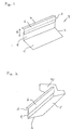
- Fig. 1 shows a very schematic representation of a flashing member according to the present invention illustrating the principle of the invention.
- the flashing member 1 comprises a first flashing portion 2 adapted to provide a seal against the roof, and a second flashing portion 3 adapted to provide a seal between the first flashing portion and the roof penetrating structure such that the composite flashing member provides a seal between the roof and the roof penetrating structure.
- the first flashing portion comprises a first sheet portion 4 and a skirt portion 5 connected to a lower part thereof, the skirt portion being arranged at an angle relative to the plane of the first sheet portion.
- the second flashing portion comprises a second sheet portion 6 as well as an optional upper flange 7 adapted to engage an upper or lower surface on a window frame portion. As illustrated by the arrow 8 the first and second sheet portions are arranged in sliding engagement and held together by cooperating, adjustable connecting means (not shown).
- the shown skirt is a plane sheet portion which is adapted to be mounted on top of a substantially planar roof surface or below a roof surface, however, for use on roof surfaces in the form of undulated tiles with deep troughs, the skirt can be made from materials which can be manually deformed or stretched during mounting to enable a good fit between the flashing and roofing, such materials including wave-undulated or pleated laminates.
- the skirt is arranged in a downwardly sloping position relative to the first sheet portion, however, the skirt may be arranged in any desired angle.
- the skirt may also be arranged in such a way that the angle between the skirt and the first sheet portion can be adjusted, for example by a connection allowing pivoting there between.
- Fig. 2 shows a preferred embodiment of the present invention, comprising, as the fig. 1 embodiment, a first flashing portion 2 with a first sheet portion 4 and a thereto connected skirt portion 5 and a second flashing portion 3 with a second sheet portion 6.
- the skirt is arranged in an upwardly sloping position relative to the first sheet portion.
- the first and second sheet portions are arranged in sliding engagement and held together by cooperating, adjustable connecting means (not shown).
- the flashing members of the present invention are particularly useful as upper and lower flashing members for a roof mounted window frame.
- a typical flashing for a roof window comprises upper and lower flashing members as well as two side flashing members.
- corner elements are provided which may be formed integrally with either the upper/lower or the side flashing members.
- the flashing member comprises a corner element 10 arranged substantially perpendicular to the general planes of the skirt 5 and the sheet portions 4, 6 at an end thereof and adapted to engage a side flashing member.
- the flashing member also comprises a corner element at the opposite end.
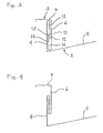
- Figs. 3 and 4 show a schematic cross-sectional view through a preferred embodiment for the adjustable flashing member of the present invention.
- the flashing member comprises a first flashing portion 2 with a first sheet portion 4 and a thereto connected skirt portion 5 and a second flashing portion 3 with a second sheet portion 6.
- the first sheet portion comprises a folded-over upper portion with a downwardly facing first flange 11 having a first free edge 12, thereby creating a first narrow fold 13 between the first sheet portion and the first flange.
- the second sheet portion 3 comprises a folded-over lower portion with an upwardly facing second flange 14 having a second free edge 15, thereby creating a second narrow fold 16 between the first sheet portion and the first flange.
- the first flange is arranged in the second fold and the second flange is arranged in the first fold by which a connection is formed between the two sheet portions.
- the flanges are arranged in such a way that the two flashing portions can be adjusted relative to each other, i.e. up- and downwards with regard to the orientation of the figures on the paper.
- Fig. 3 illustrates a flashing member in which the second flashing portion is positioned in a lower-most position relative to the first flashing portion
- fig. 4 illustrates the same flashing member in which the second flashing portion is positioned in an upper-most position relative to the first flashing portion.
- the flanges 11, 14 and free edges 12, 15 are in all positions kept in an overlapping manner which ensures that the flashing portions do not easily come apart during normal mounting procedures. Indeed, it would be possible to dismantle the two portions by sliding them away from each other along the longitudinal axes of the flanges and folds. However, additional locking means may be provided thereby fully preventing dismantling.
Landscapes
- Engineering & Computer Science (AREA)
- Architecture (AREA)
- Civil Engineering (AREA)
- Structural Engineering (AREA)
- Roof Covering Using Slabs Or Stiff Sheets (AREA)
- Catching Or Destruction (AREA)
- Seal Device For Vehicle (AREA)
Applications Claiming Priority (3)
| Application Number | Priority Date | Filing Date | Title |
|---|---|---|---|
| DK200001779 | 2000-11-25 | ||
| DKPA200001779 | 2000-11-25 | ||
| PCT/DK2001/000783 WO2002042578A1 (en) | 2000-11-25 | 2001-11-26 | Adjustable roof flashing and flashing kit |
Publications (2)
| Publication Number | Publication Date |
|---|---|
| EP1336015A1 EP1336015A1 (en) | 2003-08-20 |
| EP1336015B1 true EP1336015B1 (en) | 2009-10-07 |
Family
ID=8159867
Family Applications (1)
| Application Number | Title | Priority Date | Filing Date |
|---|---|---|---|
| EP01997602A Revoked EP1336015B1 (en) | 2000-11-25 | 2001-11-26 | Adjustable roof flashing and flashing kit |
Country Status (11)
| Country | Link |
|---|---|
| US (1) | US7059086B2 (cs) |
| EP (1) | EP1336015B1 (cs) |
| CN (1) | CN1208535C (cs) |
| AT (1) | ATE445057T1 (cs) |
| AU (1) | AU2002223019A1 (cs) |
| CZ (1) | CZ20031445A3 (cs) |
| DE (1) | DE60140140D1 (cs) |
| ES (1) | ES2334332T3 (cs) |
| HU (1) | HU223750B1 (cs) |
| PL (1) | PL364806A1 (cs) |
| WO (1) | WO2002042578A1 (cs) |
Families Citing this family (50)
| Publication number | Priority date | Publication date | Assignee | Title |
|---|---|---|---|---|
| GB0105889D0 (en) * | 2001-03-09 | 2001-04-25 | Ultraframe Uk Ltd | Flashing system |
| AU2003247849A1 (en) * | 2002-07-02 | 2004-01-23 | Kenneth Hoffman | Roof flashing strip and method of production |
| AU2003283208A1 (en) * | 2002-11-29 | 2004-06-23 | Vkr Holding A/S | A flashing device and a method of installing a roof penetrating structure by means of the flashing device |
| US6848220B2 (en) * | 2002-12-13 | 2005-02-01 | Vkr Holding A/S | Flashing |
| AU2003287886A1 (en) * | 2002-12-16 | 2004-07-09 | Vkr Holding A/S | Sheet flashing for roof windows |
| US20060053699A1 (en) * | 2004-08-25 | 2006-03-16 | Advanced Building Products, Inc. | Corner flashing |
| US20060070303A1 (en) * | 2004-10-01 | 2006-04-06 | Burnet Lemuel R Iii | Rear gutter cover closure diverter device |
| US20070220818A1 (en) * | 2006-03-23 | 2007-09-27 | Mishko Teodorovich | Concrete masonry units window and door flashing and installation |
| US8707647B2 (en) * | 2007-02-23 | 2014-04-29 | Crego Metal Systems, Inc. | Single-ply roofing system |
| US20080202040A1 (en) * | 2007-02-23 | 2008-08-28 | Crego Metal Systems, Inc. | Single ply roofing system |
| US7721489B1 (en) * | 2007-06-01 | 2010-05-25 | Metal-Era, Inc. | Vented gutter and fascia systems |
| US20090031649A1 (en) * | 2007-08-01 | 2009-02-05 | Nemazi John E | Plastic fenestration product |
| WO2009032908A1 (en) * | 2007-09-04 | 2009-03-12 | Everflash, Llc. | Deck flashing trim system |
| CA2661257C (en) * | 2008-04-01 | 2017-08-22 | Firestone Diversified Products, Llc | Wall panel system with insert |
| US20090241444A1 (en) * | 2008-04-01 | 2009-10-01 | Griffiths Robert T | Wall panel system with snap clip |
| US8316599B2 (en) * | 2008-04-01 | 2012-11-27 | Firestone Building Products Company, Llc | Wall panel system with snap-on clip |
| US8191327B2 (en) * | 2008-04-01 | 2012-06-05 | Firestone Building Products Company, Llc | Wall panel system with hook-on clip |
| US20090272055A1 (en) * | 2008-04-30 | 2009-11-05 | Griffiths Robert T | Wall panel system |
| US20100058683A1 (en) * | 2008-09-11 | 2010-03-11 | Weather-Max LLC | Adjustable sill pan assembly and system |
| CA2749162C (en) * | 2008-10-02 | 2015-08-04 | Timothy Pendley | Support for roof penetrating structures |
| US20100101168A1 (en) * | 2008-10-27 | 2010-04-29 | Mitek Holdings, Inc. | Molded polymeric drip edge |
| US20100109318A1 (en) * | 2008-10-30 | 2010-05-06 | The Garland Company, Inc. | Zinc flashing for roof penetrations |
| EP2192248B1 (en) * | 2008-11-26 | 2015-07-15 | VKR Holding A/S | Roof component flashing, a flashing system and a method of flashing |
| DE102009021542A1 (de) * | 2009-05-15 | 2010-12-02 | Roto Frank Ag | Bauelement-Anordnung |
| US8256165B2 (en) * | 2009-06-02 | 2012-09-04 | Crego Metal Systems, Inc. | Single ply roofing system |
| US9157572B1 (en) * | 2010-03-04 | 2015-10-13 | Mark Ray Merideth | Air conditioner roof support system |
| US8640477B1 (en) * | 2010-03-04 | 2014-02-04 | Uni-Products, Inc. | Hold-down bracket for securing an air conditioner to a roof mounted air conditioner support |
| US8316587B2 (en) | 2010-03-29 | 2012-11-27 | Quality Edge, Inc. | Eaves protector |
| US20110232204A1 (en) * | 2010-03-29 | 2011-09-29 | Shugart Roger F | Eaves Protector |
| US8438800B2 (en) * | 2011-03-14 | 2013-05-14 | T&M Inventions, Llc | Support structures on roofs |
| GB2507478A (en) * | 2012-09-28 | 2014-05-07 | Keystone Lintels Ltd | Flashing engaging and guiding member |
| US9187905B2 (en) | 2012-11-06 | 2015-11-17 | Jeffrey A. Smith | Roof or window panel to metal roofing or siding interface securement system |
| CN104652725B (zh) * | 2015-02-15 | 2017-03-08 | 中冶天工上海十三冶建设有限公司 | 彩钢瓦屋面烟囱的防漏结构及施工方法 |
| US10889992B2 (en) | 2018-03-15 | 2021-01-12 | Roofers Advantage Products, LLC | Roof headwall and sloped wall flashing with ledge |
| US11692353B2 (en) * | 2018-03-15 | 2023-07-04 | Roofer's Advantage Products, LLC | Double coverage roof wall flashing with cavity |
| US10774537B2 (en) * | 2018-03-15 | 2020-09-15 | Roofers' Advantage Products, Llc | Double coverage roof wall flashing with cavity |
| US10808406B2 (en) | 2018-03-15 | 2020-10-20 | Roofers' Advantage Products, Llc | Second layer roofing drip edge with protruding edge |
| US10626617B2 (en) * | 2018-09-25 | 2020-04-21 | Roofco Llc | Expandable flashing device and system |
| USD898956S1 (en) | 2019-03-15 | 2020-10-13 | Roofers' Advantage Products, Llc | Second layer drip edge |
| USD899635S1 (en) | 2019-03-15 | 2020-10-20 | Roofers' Advantage Products, Llc | Ridge vent metal cap |
| CN110886424B (zh) * | 2019-11-20 | 2023-05-26 | 上海建工四建集团有限公司 | 窗口泛水装置及其施工方法 |
| US11598100B1 (en) | 2021-09-10 | 2023-03-07 | Vicki Lepior | Roof sheath connecting apparatus and associated method of use |
| DK181527B1 (en) * | 2022-03-31 | 2024-04-05 | Vkr Holding As | A roof window and a method of mounting a roof window |
| DK181526B1 (en) * | 2022-03-31 | 2024-04-05 | Vkr Holding As | A covering device and a method for mounting a covering device at a skylight |
| USD1065609S1 (en) | 2022-06-09 | 2025-03-04 | Vicki Lepior | Roof sheathing connector |
| US11834834B1 (en) | 2022-06-29 | 2023-12-05 | Richard K. Escher | Roof fascia protection guard |
| US11933098B1 (en) | 2023-03-20 | 2024-03-19 | Pella Corporation | Fenestration unit with interior installation features and associated systems and methods |
| CA225982S (en) | 2023-03-30 | 2024-10-23 | Vkr Holding As | Window (part of-) |
| USD1052757S1 (en) | 2023-03-30 | 2024-11-26 | Vkr Holding A/S | Window |
| US20240328162A1 (en) * | 2023-04-03 | 2024-10-03 | Vkr Holding A/S | Flashing assembly comprising a top flashing arrangement, a roof element system comprising such a flashing assembly, and a method of manufacturing a flashing assembly |
Family Cites Families (25)
| Publication number | Priority date | Publication date | Assignee | Title |
|---|---|---|---|---|
| SE209300C1 (cs) * | ||||
| US1370199A (en) | 1919-11-01 | 1921-03-01 | Michael H Downs | Chimney-protector |
| US2641203A (en) * | 1952-01-07 | 1953-06-09 | Lewis B Coleman | Counterflashing and anchor cap therefor |
| DK82857C (da) | 1955-01-21 | 1957-05-27 | Rasmussen & Co V K | Anordning ved inddækninger for skråtliggende ovenlysvinduer og kappeemne til anvendelse ved disse inddækninger. |
| US3838544A (en) | 1970-12-07 | 1974-10-01 | G Hindall | Adjustable pitch pocket structure |
| DE2142733C3 (de) * | 1971-08-26 | 1980-04-03 | Hoesch Werke Ag, 4600 Dortmund | Eindeckrahmen für in der Dachfläche liegende Dachfenster |
| US3878655A (en) * | 1974-05-06 | 1975-04-22 | William S Toth | Vibration absorption system |
| US4190989A (en) * | 1978-11-15 | 1980-03-04 | Albert Sakharoff | Roof flashing system |
| SE416072B (sv) * | 1978-12-19 | 1980-11-24 | Zanda Ab | Platbeslag for anslutning av ett takpannetak till en takgenomgang, vegg eller liknande |
| US4917345A (en) | 1988-06-03 | 1990-04-17 | Midwest Mechanical, Inc. | Adjustable roof curb |
| GB2234762B (en) * | 1989-07-25 | 1993-12-01 | Knox Colin J M | Cavity tray system |
| US4951431A (en) | 1989-08-07 | 1990-08-28 | Sweers Ronald L | Chimney and wall flashing system |
| US5056277A (en) | 1990-10-29 | 1991-10-15 | Wilson William P | Preformed chimney flashing |
| US5109641A (en) * | 1991-02-19 | 1992-05-05 | Peter Halan | Roof transition flashing |
| DK82792D0 (da) * | 1992-06-23 | 1992-06-23 | Rasmussen Kann Ind As | Inddaekning til vinduer, navnlig tagvinduer |
| FR2702791B1 (fr) * | 1993-03-19 | 1995-06-09 | Dani Alu | Systeme de solin, et raccords d'angle destines a ce dernier. |
| US5381632A (en) * | 1993-05-03 | 1995-01-17 | Damron; Matthew | Chimney flashing system |
| US5409266A (en) | 1994-03-15 | 1995-04-25 | Skyline Metal Products, Inc. | Adjustable roof jack |
| DK44494A (da) * | 1994-04-18 | 1995-10-19 | Rasmussen Kann Ind As | Inddækning til tagelementer |
| DE69513162T2 (de) | 1994-04-18 | 2000-07-06 | Velux Industri A/S, Soborg | Anschlussstreifen für dachelemente |
| US5605019A (en) * | 1994-04-22 | 1997-02-25 | Maziekien; Dennis E. | Foldable and expandable pitch pocket and method of forming same |
| US5687514A (en) | 1996-01-03 | 1997-11-18 | Gillispie; John Joseph | Adjustable curb with flashing |
| JPH10299201A (ja) * | 1997-04-23 | 1998-11-10 | Sekisui Chem Co Ltd | 壁際の施工方法および壁際に用いられる雨押さえ部材 |
| US6199326B1 (en) * | 1998-04-30 | 2001-03-13 | Robert L. Mayle | Adjustable roof membrane |
| US6108981A (en) * | 1999-04-09 | 2000-08-29 | Tremco Incorporated | Surface mount counter flashing system |
-
2001
- 2001-11-26 AT AT01997602T patent/ATE445057T1/de active
- 2001-11-26 EP EP01997602A patent/EP1336015B1/en not_active Revoked
- 2001-11-26 AU AU2002223019A patent/AU2002223019A1/en not_active Abandoned
- 2001-11-26 WO PCT/DK2001/000783 patent/WO2002042578A1/en not_active Ceased
- 2001-11-26 US US10/432,527 patent/US7059086B2/en not_active Expired - Fee Related
- 2001-11-26 PL PL01364806A patent/PL364806A1/xx not_active Application Discontinuation
- 2001-11-26 DE DE60140140T patent/DE60140140D1/de not_active Expired - Lifetime
- 2001-11-26 HU HU0302947A patent/HU223750B1/hu not_active IP Right Cessation
- 2001-11-26 CZ CZ20031445A patent/CZ20031445A3/cs unknown
- 2001-11-26 ES ES01997602T patent/ES2334332T3/es not_active Expired - Lifetime
- 2001-11-26 CN CNB01819530XA patent/CN1208535C/zh not_active Expired - Fee Related
Also Published As
| Publication number | Publication date |
|---|---|
| PL364806A1 (en) | 2004-12-13 |
| CN1208535C (zh) | 2005-06-29 |
| HU223750B1 (hu) | 2004-12-28 |
| ATE445057T1 (de) | 2009-10-15 |
| US7059086B2 (en) | 2006-06-13 |
| HUP0302947A2 (en) | 2004-01-28 |
| EP1336015A1 (en) | 2003-08-20 |
| CN1489663A (zh) | 2004-04-14 |
| CZ20031445A3 (cs) | 2003-11-12 |
| DE60140140D1 (de) | 2009-11-19 |
| WO2002042578A1 (en) | 2002-05-30 |
| ES2334332T3 (es) | 2010-03-09 |
| US20040103592A1 (en) | 2004-06-03 |
| AU2002223019A1 (en) | 2002-06-03 |
Similar Documents
| Publication | Publication Date | Title |
|---|---|---|
| EP1336015B1 (en) | Adjustable roof flashing and flashing kit | |
| US5522189A (en) | Flashing for roof elements | |
| US7308777B2 (en) | Method of forming a standing seam skylight | |
| US6457279B1 (en) | Flashing member and frame for a roof-penetrating building part | |
| EP3966401B1 (en) | Flashing assembly for a roof penetrating structure and a method for manufacturing a flashing assembly | |
| US5644886A (en) | Roofing | |
| EP1485547B1 (en) | Flashing kit | |
| EP3404162B1 (en) | A roof window installed in an inclined roof structure with a flashing assembly and a method for weather proofing a roof window | |
| EP1579093B1 (en) | Flashing member with adaptable corner segments | |
| US20110283649A1 (en) | Paneling system | |
| PL224719B1 (pl) | Zestaw konstrukcji przenikających przez dach z obróbką blacharską | |
| EP0756659B1 (en) | A flashing for roof elements | |
| EP1567732B1 (en) | A flashing device and a method of installing a roof penetrating structure by means of the flashing device | |
| EP1576244B1 (en) | Sheet flashing for roof windows and method for flashing a roof penetrating building structure | |
| EP3599321B1 (en) | Kit of parts and method of flashing a roof element | |
| FI96712B (fi) | Menetelmä sileästä ohutlevystä valmistetun, pystysaumoilla varustetun katteen kiinnityksen varmistamiseksi sekä menetelmän käyttö lumiesteiden, kulkusiltojen ja kattotikkaiden jalkojen kiinnityksen varmistamiseksi | |
| AU2007202222A1 (en) | Roof gap sealing method and apparatus | |
| EP0985780A1 (de) | Abdeckung für Dächer oder Fassaden | |
| NZ555263A (en) | Hip ridge end cap |
Legal Events
| Date | Code | Title | Description |
|---|---|---|---|
| PUAI | Public reference made under article 153(3) epc to a published international application that has entered the european phase |
Free format text: ORIGINAL CODE: 0009012 |
|
| 17P | Request for examination filed |
Effective date: 20030512 |
|
| AK | Designated contracting states |
Designated state(s): AT BE CH CY DE DK ES FI FR GB GR IE IT LI LU MC NL PT SE TR |
|
| AX | Request for extension of the european patent |
Extension state: AL LT LV MK RO SI |
|
| RAP1 | Party data changed (applicant data changed or rights of an application transferred) |
Owner name: VKR HOLDING A/S |
|
| GRAP | Despatch of communication of intention to grant a patent |
Free format text: ORIGINAL CODE: EPIDOSNIGR1 |
|
| GRAS | Grant fee paid |
Free format text: ORIGINAL CODE: EPIDOSNIGR3 |
|
| GRAA | (expected) grant |
Free format text: ORIGINAL CODE: 0009210 |
|
| AK | Designated contracting states |
Kind code of ref document: B1 Designated state(s): AT BE CH CY DE DK ES FI FR GB GR IE IT LI LU MC NL PT SE TR |
|
| REG | Reference to a national code |
Ref country code: GB Ref legal event code: FG4D |
|
| REG | Reference to a national code |
Ref country code: CH Ref legal event code: EP |
|
| REG | Reference to a national code |
Ref country code: IE Ref legal event code: FG4D |
|
| REF | Corresponds to: |
Ref document number: 60140140 Country of ref document: DE Date of ref document: 20091119 Kind code of ref document: P |
|
| REG | Reference to a national code |
Ref country code: ES Ref legal event code: FG2A Ref document number: 2334332 Country of ref document: ES Kind code of ref document: T3 |
|
| PG25 | Lapsed in a contracting state [announced via postgrant information from national office to epo] |
Ref country code: FI Free format text: LAPSE BECAUSE OF FAILURE TO SUBMIT A TRANSLATION OF THE DESCRIPTION OR TO PAY THE FEE WITHIN THE PRESCRIBED TIME-LIMIT Effective date: 20091007 Ref country code: SE Free format text: LAPSE BECAUSE OF FAILURE TO SUBMIT A TRANSLATION OF THE DESCRIPTION OR TO PAY THE FEE WITHIN THE PRESCRIBED TIME-LIMIT Effective date: 20091007 Ref country code: PT Free format text: LAPSE BECAUSE OF FAILURE TO SUBMIT A TRANSLATION OF THE DESCRIPTION OR TO PAY THE FEE WITHIN THE PRESCRIBED TIME-LIMIT Effective date: 20100208 |
|
| PG25 | Lapsed in a contracting state [announced via postgrant information from national office to epo] |
Ref country code: MC Free format text: LAPSE BECAUSE OF NON-PAYMENT OF DUE FEES Effective date: 20091130 |
|
| PLBI | Opposition filed |
Free format text: ORIGINAL CODE: 0009260 |
|
| PG25 | Lapsed in a contracting state [announced via postgrant information from national office to epo] |
Ref country code: DK Free format text: LAPSE BECAUSE OF FAILURE TO SUBMIT A TRANSLATION OF THE DESCRIPTION OR TO PAY THE FEE WITHIN THE PRESCRIBED TIME-LIMIT Effective date: 20091007 |
|
| PLAX | Notice of opposition and request to file observation + time limit sent |
Free format text: ORIGINAL CODE: EPIDOSNOBS2 |
|
| 26 | Opposition filed |
Opponent name: FAKRO PP SPOLKA Z.O.O. Effective date: 20100707 Opponent name: ROTO FRANK AG Effective date: 20100705 |
|
| PG25 | Lapsed in a contracting state [announced via postgrant information from national office to epo] |
Ref country code: GR Free format text: LAPSE BECAUSE OF FAILURE TO SUBMIT A TRANSLATION OF THE DESCRIPTION OR TO PAY THE FEE WITHIN THE PRESCRIBED TIME-LIMIT Effective date: 20100108 Ref country code: IE Free format text: LAPSE BECAUSE OF NON-PAYMENT OF DUE FEES Effective date: 20091126 |
|
| PLAF | Information modified related to communication of a notice of opposition and request to file observations + time limit |
Free format text: ORIGINAL CODE: EPIDOSCOBS2 |
|
| PLBB | Reply of patent proprietor to notice(s) of opposition received |
Free format text: ORIGINAL CODE: EPIDOSNOBS3 |
|
| PG25 | Lapsed in a contracting state [announced via postgrant information from national office to epo] |
Ref country code: LU Free format text: LAPSE BECAUSE OF NON-PAYMENT OF DUE FEES Effective date: 20091126 |
|
| PG25 | Lapsed in a contracting state [announced via postgrant information from national office to epo] |
Ref country code: TR Free format text: LAPSE BECAUSE OF FAILURE TO SUBMIT A TRANSLATION OF THE DESCRIPTION OR TO PAY THE FEE WITHIN THE PRESCRIBED TIME-LIMIT Effective date: 20091007 |
|
| PG25 | Lapsed in a contracting state [announced via postgrant information from national office to epo] |
Ref country code: CY Free format text: LAPSE BECAUSE OF FAILURE TO SUBMIT A TRANSLATION OF THE DESCRIPTION OR TO PAY THE FEE WITHIN THE PRESCRIBED TIME-LIMIT Effective date: 20091007 |
|
| PLAB | Opposition data, opponent's data or that of the opponent's representative modified |
Free format text: ORIGINAL CODE: 0009299OPPO |
|
| R26 | Opposition filed (corrected) |
Opponent name: ROTO FRANK AG Effective date: 20100705 Opponent name: FAKRO PP SPOLKA Z.O.O. Effective date: 20100707 |
|
| REG | Reference to a national code |
Ref country code: DE Ref legal event code: R103 Ref document number: 60140140 Country of ref document: DE Ref country code: DE Ref legal event code: R064 Ref document number: 60140140 Country of ref document: DE |
|
| RDAF | Communication despatched that patent is revoked |
Free format text: ORIGINAL CODE: EPIDOSNREV1 |
|
| PGFP | Annual fee paid to national office [announced via postgrant information from national office to epo] |
Ref country code: FR Payment date: 20121130 Year of fee payment: 12 Ref country code: DE Payment date: 20121121 Year of fee payment: 12 Ref country code: CH Payment date: 20121113 Year of fee payment: 12 |
|
| PGFP | Annual fee paid to national office [announced via postgrant information from national office to epo] |
Ref country code: IT Payment date: 20121010 Year of fee payment: 12 Ref country code: ES Payment date: 20121212 Year of fee payment: 12 Ref country code: BE Payment date: 20121113 Year of fee payment: 12 Ref country code: GB Payment date: 20121121 Year of fee payment: 12 |
|
| PGFP | Annual fee paid to national office [announced via postgrant information from national office to epo] |
Ref country code: AT Payment date: 20121029 Year of fee payment: 12 Ref country code: NL Payment date: 20121110 Year of fee payment: 12 |
|
| RDAG | Patent revoked |
Free format text: ORIGINAL CODE: 0009271 |
|
| STAA | Information on the status of an ep patent application or granted ep patent |
Free format text: STATUS: PATENT REVOKED |
|
| REG | Reference to a national code |
Ref country code: CH Ref legal event code: PL |
|
| 27W | Patent revoked |
Effective date: 20121123 |
|
| GBPR | Gb: patent revoked under art. 102 of the ep convention designating the uk as contracting state |
Effective date: 20121123 |
|
| PG25 | Lapsed in a contracting state [announced via postgrant information from national office to epo] |
Ref country code: CH Free format text: LAPSE BECAUSE OF THE APPLICANT RENOUNCES Effective date: 20091007 Ref country code: LI Free format text: LAPSE BECAUSE OF THE APPLICANT RENOUNCES Effective date: 20091007 |
|
| REG | Reference to a national code |
Ref country code: DE Ref legal event code: R107 Ref document number: 60140140 Country of ref document: DE Effective date: 20130926 |
|
| REG | Reference to a national code |
Ref country code: AT Ref legal event code: MA03 Ref document number: 445057 Country of ref document: AT Kind code of ref document: T Effective date: 20121123 |