EP1335147A2 - Schnappscheibeneinrichtung - Google Patents
Schnappscheibeneinrichtung Download PDFInfo
- Publication number
- EP1335147A2 EP1335147A2 EP03250800A EP03250800A EP1335147A2 EP 1335147 A2 EP1335147 A2 EP 1335147A2 EP 03250800 A EP03250800 A EP 03250800A EP 03250800 A EP03250800 A EP 03250800A EP 1335147 A2 EP1335147 A2 EP 1335147A2
- Authority
- EP
- European Patent Office
- Prior art keywords
- disc
- fastener
- radial point
- gravity
- center
- Prior art date
- Legal status (The legal status is an assumption and is not a legal conclusion. Google has not performed a legal analysis and makes no representation as to the accuracy of the status listed.)
- Withdrawn
Links
Images





Classifications
-
- F—MECHANICAL ENGINEERING; LIGHTING; HEATING; WEAPONS; BLASTING
- F16—ENGINEERING ELEMENTS AND UNITS; GENERAL MEASURES FOR PRODUCING AND MAINTAINING EFFECTIVE FUNCTIONING OF MACHINES OR INSTALLATIONS; THERMAL INSULATION IN GENERAL
- F16B—DEVICES FOR FASTENING OR SECURING CONSTRUCTIONAL ELEMENTS OR MACHINE PARTS TOGETHER, e.g. NAILS, BOLTS, CIRCLIPS, CLAMPS, CLIPS OR WEDGES; JOINTS OR JOINTING
- F16B21/00—Means for preventing relative axial movement of a pin, spigot, shaft or the like and a member surrounding it; Stud-and-socket releasable fastenings
- F16B21/10—Means for preventing relative axial movement of a pin, spigot, shaft or the like and a member surrounding it; Stud-and-socket releasable fastenings by separate parts
- F16B21/20—Means for preventing relative axial movement of a pin, spigot, shaft or the like and a member surrounding it; Stud-and-socket releasable fastenings by separate parts for bolts or shafts without holes, grooves, or notches for locking members
-
- F—MECHANICAL ENGINEERING; LIGHTING; HEATING; WEAPONS; BLASTING
- F16—ENGINEERING ELEMENTS AND UNITS; GENERAL MEASURES FOR PRODUCING AND MAINTAINING EFFECTIVE FUNCTIONING OF MACHINES OR INSTALLATIONS; THERMAL INSULATION IN GENERAL
- F16B—DEVICES FOR FASTENING OR SECURING CONSTRUCTIONAL ELEMENTS OR MACHINE PARTS TOGETHER, e.g. NAILS, BOLTS, CIRCLIPS, CLAMPS, CLIPS OR WEDGES; JOINTS OR JOINTING
- F16B39/00—Locking of screws, bolts or nuts
- F16B39/02—Locking of screws, bolts or nuts in which the locking takes place after screwing down
- F16B39/10—Locking of screws, bolts or nuts in which the locking takes place after screwing down by a plate, spring, wire or ring immovable with regard to the bolt or object and mainly perpendicular to the axis of the bolt
-
- F—MECHANICAL ENGINEERING; LIGHTING; HEATING; WEAPONS; BLASTING
- F16—ENGINEERING ELEMENTS AND UNITS; GENERAL MEASURES FOR PRODUCING AND MAINTAINING EFFECTIVE FUNCTIONING OF MACHINES OR INSTALLATIONS; THERMAL INSULATION IN GENERAL
- F16B—DEVICES FOR FASTENING OR SECURING CONSTRUCTIONAL ELEMENTS OR MACHINE PARTS TOGETHER, e.g. NAILS, BOLTS, CIRCLIPS, CLAMPS, CLIPS OR WEDGES; JOINTS OR JOINTING
- F16B39/00—Locking of screws, bolts or nuts
- F16B39/22—Locking of screws, bolts or nuts in which the locking takes place during screwing down or tightening
- F16B39/24—Locking of screws, bolts or nuts in which the locking takes place during screwing down or tightening by means of washers, spring washers, or resilient plates that lock against the object
-
- F—MECHANICAL ENGINEERING; LIGHTING; HEATING; WEAPONS; BLASTING
- F16—ENGINEERING ELEMENTS AND UNITS; GENERAL MEASURES FOR PRODUCING AND MAINTAINING EFFECTIVE FUNCTIONING OF MACHINES OR INSTALLATIONS; THERMAL INSULATION IN GENERAL
- F16B—DEVICES FOR FASTENING OR SECURING CONSTRUCTIONAL ELEMENTS OR MACHINE PARTS TOGETHER, e.g. NAILS, BOLTS, CIRCLIPS, CLAMPS, CLIPS OR WEDGES; JOINTS OR JOINTING
- F16B43/00—Washers or equivalent devices; Other devices for supporting bolt-heads or nuts
-
- F—MECHANICAL ENGINEERING; LIGHTING; HEATING; WEAPONS; BLASTING
- F16—ENGINEERING ELEMENTS AND UNITS; GENERAL MEASURES FOR PRODUCING AND MAINTAINING EFFECTIVE FUNCTIONING OF MACHINES OR INSTALLATIONS; THERMAL INSULATION IN GENERAL
- F16F—SPRINGS; SHOCK-ABSORBERS; MEANS FOR DAMPING VIBRATION
- F16F1/00—Springs
- F16F1/02—Springs made of steel or other material having low internal friction; Wound, torsion, leaf, cup, ring or the like springs, the material of the spring not being relevant
- F16F1/32—Belleville-type springs
- F16F1/324—Belleville-type springs characterised by having tongues or arms directed in a generally radial direction, i.e. diaphragm-type springs
Definitions
- the subject invention generally pertains to a snap disc device, and more specifically pertains a snap disc device whose particular geometry provides exceptional operating characteristics.
- Belleville washers are resiliently compressible conical washers that provide a spring effect. For a given length, Belleville washers typically have much higher spring rates and significantly less travel than compression springs. This limits the use of Bellville washers to applications requiring relatively high forces and little travel. Belleville washers can be stacked back-to-back to provide lower spring rates and more travel, but a stack of washers will of course consume more space.
- Curved disc springs have the shape of a flat washer that has been bent or bowed about a line parallel to the face of the washer. For a given size, a single curved disc springs may provide a lower spring rate than that of a Bellville washer. However, stacking curved disc springs to achieve even lower spring rates can be difficult to accomplish. Stacking the springs peak-to-peak is difficult to maintain, as the discs are normally free to rotate to a more stable arrangement of peak-to-valley.
- Wave disc springs are similar to curved disc springs, but with more bends to create a wavy shape. Just as with curved disc springs, it can be difficult to maintain a stack of wave disc springs in a peak-to-peak arrangement. For a given size, wave disc springs tend to have less travel than curved disc springs.
- Finger disc springs comprise an annular disc whose outer perimeter includes several fingers that are bent out of coplanar alignment with the rest of the disc.
- the fingers can resiliently deflect to create a spring-like effect.
- the fingers may also interfere with being able to effectively stack finger disc springs with predictable results.
- Snap disc devices invented by Pierre Schwab and disclosed in U. S. Patents 4,822,959 and 5,269,499, have clover leaf shapes to create a bi-stable snap-action.
- the physical structure, operating characteristics, and/or method of pre-stressing such snap discs limits their usefulness.
- an object of some embodiments of the invention is to provide an elastic disc that serves as a fastener by gripping the four sides of a square shaft.
- Another object of some embodiments of the invention is to provide a fastener with a particular disc geometry that provides the fastener with a surprisingly high coefficient of compliance, and yet the fastener is readily stackable to lower or increase its spring rate.
- Another object of some embodiments is to provide a fastener with a threaded member, wherein the fastener indicates the degree of tightness to which the threaded member compresses a bowed disc a predetermined amount of deflection against a standoff element.
- Another object of some embodiments is to provide a disc-like fastener that helps inhibit a threaded fastener from unscrewing under vibration.
- Another object of some embodiments is to provide a fastener with a threaded member, wherein the fastener indicates the degree of tightness to which the threaded member compresses a bowed disc a predetermined amount of deflection against a standoff element, and wherein the standoff element is a simple unitary ring.
- Another object of some embodiments of the invention is to provide a fastener with a particular disc geometry that provides the fastener with a lower spring rate and more travel than a Belleville washer of similar material, thickness and diameter.
- Another object of some embodiments of the invention is to provide a fastener with a particular disc geometry that provides the fastener with a higher coefficient of compliance than a Belleville washer of similar material, thickness and diameter.
- Another object of some embodiments of the invention is to provide a fastener with a particular disc geometry that provides the fastener with spring characteristics that are generally between that of a Belleville washer and a compression spring.
- Another object of the invention is to provide a cloverleaf shaped disc having a bowed shaped when it its normally unstressed position.
- Another object of some embodiments is to provide a cloverleaf disc with radial protrusions around its outer perimeter that provide the disc with more freedom to deflect.
- Another object is to provide a disc fastener that is radially symmetrical so it can be installed alone or in a stacked arrangement regardless of its rotational orientation.
- Another object of some embodiments is to provide a disc fastener with ample travel and a significant spring rate even though the disk has a rather large diameter to thickness ratio.
- Another object of some embodiments is to provide a disc fastener whose material thickness is less than 5% of its diameter, thereby making the disc especially useful where axial space is limited.
- a disc fastener having an outer edge and an inner edge, wherein portions of the inner edge extend radially further out than some portions of the outer edge.
- the disc's geometry provides a coefficient of compliance greater than 10, wherein the coefficient of compliance is defined as the disc's thickness cubed divided by a product of the disc's spring constant at 75% compression times the disc's effective outer diameter squared, wherein the thickness is expressed in mils, the spring constant is expressed in pounds per inch, and the effective outer diameter is expressed in inches.
- a fastener shown in Figures 1 and 2 includes a disc 10 with various design features that provide the fastener with the versatility to perform a variety of functions.
- Disc 10 (as shown or with some modification) can selectively serve as a variety of devices including, but not limited to, a compression spring, a shaft or bar locking element, or tightness indicator for a threaded fastener.
- Disc 10 is preformed so that its face surface 12 assumes a bowed or conical shape when in its unstressed position of zero percent (i.e., the disc's natural relaxed state, as shown by various discs in Figures 1, 2, 3, 4, 5, 12, 13 and 16).
- a fully stressed position of 100% is where a disc is completely flattened out, as shown in Figure 18.
- An intermediate position is when a disc is compressed to a position between its unstressed position of zero percent and its fully stressed position of 100%.
- Figures 14, 15 and 17 show a disc compressed to an intermediate position of 75%, wherein the disc has been compressed 75% of its full travel distance toward its fully stressed position of 100% (e.g., if the disc's full travel is .100 inches, the disc is compressed .075 inches to reach an intermediate position of 75%).
- disc 10 includes a curved outer edge 14 and an inner edge 16.
- a minimum radial point 18 on outer edge 14 is at least as close to the disc's center of gravity 20 as is a maximum radial point 22 on inner edge 16. In some embodiments, minimum radial point 18 is preferably closer to the disc's center of gravity 20 than is maximum radial point 22 on inner edge 16.
- disc 24 of Figures 3 and 4 includes a curved outer edge 26 and an inner edge 28.
- a minimum radial point 30 on outer edge 26 is at least as close to the disc's center of gravity 32 as is a maximum radial point 34 on inner edge 28.
- disc 36 also includes a curved outer edge 38 and an inner edge 40.
- a minimum radial point 42 on outer edge 38 is closer to the disc's center of gravity 44 than is a maximum radial point 46 on inner edge 40.
- Discs 10, 24 and 36 can be made of a variety of materials including, but not limited to carbon steel alloys, stainless steel alloys, copper alloys, inconel, monel, plastics and temperature responsive materials.
- Disc 48 of Figure 6, for example, is made of bimetal where two intimately joined layers of material 50 and 52 have different coefficients of thermal expansion, so that disc 48 deflects as its temperature changes. Such a disc may be useful as a temperature sensor.
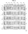
- discs 10, 24 and 36 are provided with a thickness 54, an effective outer diameter 56, an effective inner diameter 58, and a 75% compression stroke 60 that produces a coefficient of compliance 62 in the range often to fifteen with an unusual spring rate 64 (i.e., axial compression force 66 divided by deflection 60, as shown in Figure 7.
- an unusual spring rate 64 i.e., axial compression force 66 divided by deflection 60, as shown in Figure 7.
- Such characteristics can be achieved when the disc is made of an iron or iron alloy (e.g., steel, stainless steel, etc.) having a tensile strength of 60 to 250 psi and/or a modulus of elasticity of 25x10 6 to 35x10 6 psi.
- the "coefficient of compliance” pertains to a spring's degree of compliance and is defined herein as a ratio of a disc's thickness cubed (in units of cubic mils) divided by the product of the disc's effective diameter squared (in units of square inches) times the disc's spring constant (in units of pounds-force per inch of compression at the disc's intermediate position of 75%).
- the "effective diameter" of a disc is defined as the diameter of the smallest circle in which the outer edge of the disc can be inscribed.
- Disc 24 has an effective diameter 68, as shown in Figure 3
- disc 36 has an effective diameter 76, as shown in Figure 5.
- Disc 36 includes a plurality of protrusions 78 extending radially outward from the disc's outer edge 38, whereby a distal edge 80 of each protrusion 78 defines effective diameter 76.
- Protrusions 78 provide disc 36 with discrete points of contact around the disc's outer perimeter. In some applications, such points of contact allow disc 36 to flex more freely without inhibiting the disc's outer perimeter from flexing.
- an average coefficient of compliance 84 of discs 10, 24, 36 and 82 is 12.3 with a range of 10.3 to 13.7. Similar embodiments can provide a coefficient of compliance ranging from 10 to 15.
- some Bellville washers 86 may provide an average coefficient of compliance 88 of 4.2 with a range of 4.0 to 4.4; some curved washers 90 may provide an average coefficient of compliance 92 of 21.3 with a range of 17 to 23; some wave washers 94 may provide an average coefficient of compliance 96 of 3.5 with a range of 3 to 5; and some finger washers 98 may provide an average coefficient of compliance 100 of 4.8 with a range of 2 to 8.5.
- discs 10, 24, 36 and 82 Besides the coefficient of compliance, other characteristics of discs 10, 24, 36 and 82 distinguish them from comparably sized Bellville washers, curved washers, wave washers and finger washers. Generally speaking, discs 10, 24, 36 and 82 have significantly greater deflection than Bellville washers 86, they have a much lower spring rate than Bellville washers 86, they resist a greater force of deflection than curved washers 90, they have greater deflection than wave washers 94, and they have a higher spring rate than finger washers 98.
- Figure 7 is for general comparison purposes wherein discs 10, 24, 36, 82, 86, 90, 94 and 98 are of a generally similar material, i.e., made of an iron or iron alloy, and/or made of a material having a tensile strength of 60 to 250 psi and/or a modulus of elasticity of 25x10 6 to 35x10 6 psi.
- disc 24 can serve as an effective rod-clamping device, as shown in Figures 8 and 9.
- disc 24 can be forced over a generally smooth round rod 102, so inner edge 28 of disc 24 can grip rod 102 without rod 102 having to include an additional holding feature, such as a groove or shoulder.
- Two discs 24 facing in opposite directions can hold one or more members 104 at a generally fixed location along rod 102.
- disc 10 is provided with an inner edge 16 having four linear edges 106 that are able to grip four faces 108 of a square bar 110, as shown in Figures 1, 2, 10 and 11. Two opposite facing discs 10 gripping bar 110 are able to hold bar 110 fixed relative to one or more members 112.
- Disc 10 in this case, has an inner diameter 114 defined by the largest circle 116 that can be inscribed within the inner edge 16 of disc 10.
- a standoff element such as a ring 116
- disc 24 may be attached or simply placed adjacent to disc 24 to inhibit the disc from deflecting completely to its fully stressed or flat position.
- disc 24 can be compressed between a first surface 118 (e.g., underneath an internally threaded member, such as a nut 120) and a second surface 122, thereby compressing disc 24 from its unstressed position of Figure 13 to an intermediate position of Figure 14.
- disc 24 may be compressed between a first surface 126 (underneath the head of an externally threaded member, such as a bolt 124, screw, etc.) and a second surface 128.
- the standoff element can be an integral part of the threaded member that compresses the disc.
- a shoulder 130 on threaded member 132 provides a standoff that inhibits disc 24 from being compressed beyond its intermediate position of Figure 17. Once nut 120 is tightened against shoulder 130, further compression of disc 24 is inhibited. Of course, if shoulder 130 does not extend beyond the total thickness of members 134 and 136, then disc 24 could be compressed to its fully stressed position of 100%, as shown in Figure 18.
- the radial symmetry of disc 24 allows two or more discs to be stacked, as shown in Figure 19.
- the expressions, "radial symmetry" and “radially symmetrical” describe a shape, wherein the entire shape can be divided into substantially identical pie pieces.
- Stacking discs 24 as shown in Figure 19 allows the discs to resist an overall greater compressive force for a given amount of deflection. To achieve greater deflection for a given amount of compressive force, discs 24 can be stacked as shown in Figure 20.
Landscapes
- Engineering & Computer Science (AREA)
- General Engineering & Computer Science (AREA)
- Mechanical Engineering (AREA)
- Bolts, Nuts, And Washers (AREA)
- Springs (AREA)
- Slide Fasteners, Snap Fasteners, And Hook Fasteners (AREA)
Applications Claiming Priority (2)
| Application Number | Priority Date | Filing Date | Title |
|---|---|---|---|
| US67603 | 2002-02-07 | ||
| US10/067,603 US6705813B2 (en) | 2002-02-07 | 2002-02-07 | Snap disc device |
Publications (2)
| Publication Number | Publication Date |
|---|---|
| EP1335147A2 true EP1335147A2 (de) | 2003-08-13 |
| EP1335147A3 EP1335147A3 (de) | 2004-08-11 |
Family
ID=27610517
Family Applications (1)
| Application Number | Title | Priority Date | Filing Date |
|---|---|---|---|
| EP03250800A Withdrawn EP1335147A3 (de) | 2002-02-07 | 2003-02-07 | Schnappscheibeneinrichtung |
Country Status (2)
| Country | Link |
|---|---|
| US (1) | US6705813B2 (de) |
| EP (1) | EP1335147A3 (de) |
Cited By (6)
| Publication number | Priority date | Publication date | Assignee | Title |
|---|---|---|---|---|
| DE10323577A1 (de) * | 2003-05-26 | 2004-12-30 | Christian Bauer Gmbh + Co | An einer kreiszylindrischen Oberfläche eines Aufnahmekörpers axial verschiebegesicherte Tellerfeder |
| CN101611244B (zh) * | 2007-02-14 | 2013-06-12 | 伊顿公司 | 包括弹性盘装置的改进的锁止差速器 |
| CN103362936A (zh) * | 2013-08-05 | 2013-10-23 | 无锡市张泾宇钢机械厂 | 弹性垫片 |
| CN103398084A (zh) * | 2013-08-05 | 2013-11-20 | 无锡市张泾宇钢机械厂 | 简易防松垫片 |
| CN103697045A (zh) * | 2013-12-31 | 2014-04-02 | 江苏金铁人自动化科技有限公司 | 一种预紧装置 |
| WO2021256562A1 (en) * | 2020-06-19 | 2021-12-23 | Daikin Industries, Ltd. | System and method for magnetic bearings |
Families Citing this family (72)
| Publication number | Priority date | Publication date | Assignee | Title |
|---|---|---|---|---|
| US6860688B2 (en) * | 2001-06-15 | 2005-03-01 | Danley Construction Products Pty Ltd | Lockable nut system |
| DE20206373U1 (de) * | 2002-04-23 | 2002-08-08 | Textron Verbindungstechnik GmbH & Co. oHG, 56567 Neuwied | Selbstsichernde Befestigungseinrichtung |
| AU2003252156A1 (en) * | 2002-07-25 | 2004-02-16 | Cooper-Standard Automotive Inc. | Break-away cradle or sub-frame mount and retainer washer assembly |
| US20040016046A1 (en) | 2002-07-26 | 2004-01-29 | Siegal David M. | Push-on bolt stabilizer |
| US6899199B2 (en) * | 2002-10-24 | 2005-05-31 | Barnes Group Inc. | Flapper finger valve assembly |
| USD528407S1 (en) * | 2003-02-03 | 2006-09-19 | Schwab Pierre P | Snap disc element |
| KR100555549B1 (ko) * | 2004-01-28 | 2006-03-03 | 삼성전자주식회사 | 하드 디스크 드라이브의 디스크 클램핑 장치 |
| US7128328B2 (en) * | 2004-02-18 | 2006-10-31 | Automotive Components Holdings, Llc | Mechanical stop for a rigid bar |
| US20060054771A1 (en) * | 2004-09-13 | 2006-03-16 | Lie Chien C | Level hanger device for pictures or the like |
| DE102004060305B4 (de) * | 2004-12-15 | 2006-09-21 | Audi Ag | Befestigungselement für eine Anordnung von Bauteilen |
| DE202005002663U1 (de) * | 2005-02-19 | 2006-06-29 | Fischerwerke Artur Fischer Gmbh & Co. Kg | Unterlegscheibe für eine Schraube mit Beffe |
| US7665300B2 (en) | 2005-03-11 | 2010-02-23 | Massachusetts Institute Of Technology | Thin, flexible actuator array to produce complex shapes and force distributions |
| US7198445B2 (en) * | 2005-06-03 | 2007-04-03 | Fan Disc Corporation | Washer with crush zone |
| US20070018147A1 (en) * | 2005-07-25 | 2007-01-25 | Damon John Iii | Fence wire fastener |
| US10900539B2 (en) | 2005-12-30 | 2021-01-26 | Fox Factory, Inc. | Fluid damper having a damping profile favorable for absorbing the full range of compression forces, including low- and high-speed compression forces |
| ATE451560T1 (de) * | 2006-10-19 | 2009-12-15 | Elringklinger Ag | Kombination aus einer schraube, einer unterlegscheibe und einer hülse sowie verfahren zum herstellen einer solchen kombination |
| EP2047125B1 (de) * | 2006-10-19 | 2010-10-06 | ElringKlinger AG | Hülse |
| WO2008073907A2 (en) * | 2006-12-08 | 2008-06-19 | Alpinespine Llc | Compliant cervical screw locking mechanism |
| DE102007007593B4 (de) * | 2007-02-13 | 2011-01-13 | Sig Technology Ag | Sicherungsring |
| US7605336B2 (en) * | 2007-08-30 | 2009-10-20 | Honeywell International Inc. | Pressure switch with adjustable differental setting |
| US8474374B2 (en) * | 2007-09-06 | 2013-07-02 | Russell T. Trovinger | Juicer with alternate cutters |
| US8172902B2 (en) * | 2008-07-17 | 2012-05-08 | Spinemedica, Llc | Spinal interbody spacers |
| DE102008040677A1 (de) * | 2008-07-24 | 2010-01-28 | Hilti Aktiengesellschaft | Ringscheibenförmiges Verankerungselement |
| US8281603B2 (en) * | 2008-08-11 | 2012-10-09 | United Technologies Corporation | Fastener assembly for connecting rocket engine nozzles |
| CN201373017Y (zh) * | 2009-02-17 | 2009-12-30 | 深圳富泰宏精密工业有限公司 | 垫片及应用该垫片的铰链结构 |
| WO2011018476A2 (en) | 2009-08-12 | 2011-02-17 | Vilis Ivars Lietuvietis | Direct injection injector for internal combustion engine |
| DE102010060771A1 (de) * | 2009-12-16 | 2011-06-22 | fischerwerke GmbH & Co. KG, 72178 | Befestigungselement |
| NL2004126C2 (nl) * | 2010-01-21 | 2011-07-25 | Speed Fix Ip B V | Samenstel van door een koppelstang en een moer gevormde bevestigingselementen, koppelstang, en moer. |
| WO2011103030A1 (en) * | 2010-02-18 | 2011-08-25 | Huffy Corporation | Tool-less pedal assembly |
| US9010072B2 (en) * | 2010-03-26 | 2015-04-21 | Tipper Tie, Inc. | Multiple station automated bagger systems, associated devices and related methods |
| US20120192379A1 (en) * | 2011-01-28 | 2012-08-02 | Windgate Products Co., Inc. | Bushing |
| US9376807B2 (en) * | 2011-08-23 | 2016-06-28 | Teledyne Scientific & Imaging, Llc | Passive structures with high stiffness and high damping properties |
| JP2015038906A (ja) * | 2012-02-27 | 2015-02-26 | 株式会社東芝 | 電子機器、支持装置、取付構造 |
| CN102785597A (zh) * | 2012-08-23 | 2012-11-21 | 上海交运汽车精密冲压件有限公司 | 座椅调角器的传力杆轴向限位结构 |
| JP6148841B2 (ja) * | 2012-09-27 | 2017-06-14 | 日本航空電子工業株式会社 | ワッシャ |
| US9615815B2 (en) | 2012-09-28 | 2017-04-11 | Clemson University Research Foundation | Devices that cooperate with ultrasound probes for muscoskeletal evaluations and related systems and methods |
| USD692747S1 (en) | 2013-03-13 | 2013-11-05 | Pierre P. Schwab | Disc spring |
| USD703034S1 (en) | 2013-08-22 | 2014-04-22 | Alpha Stamping Company | Retainer |
| DE102013217401B3 (de) * | 2013-09-02 | 2014-12-11 | Ringspann Gmbh | Spannvorrichtung |
| DE102013218650A1 (de) * | 2013-09-18 | 2015-03-19 | Bayerische Motoren Werke Aktiengesellschaft | Befestigungskralle |
| EP2860592B1 (de) * | 2013-10-09 | 2023-07-05 | Nivarox-FAR S.A. | Montagesystem, bei dem ein flaches elastisches blockierelement verwendet wird |
| EP2860591B1 (de) * | 2013-10-09 | 2025-07-16 | Nivarox-FAR S.A. | Montagesystem, bei dem ein konisches elastisches Blockierelement verwendet wird |
| US9452516B2 (en) * | 2014-02-10 | 2016-09-27 | Pouria Alavi | Socket for socket wrench |
| DE102014202359A1 (de) * | 2014-02-10 | 2015-08-13 | Bayerische Motoren Werke Aktiengesellschaft | Verfahren zum Fixieren von Bauteilen |
| US9995336B2 (en) * | 2014-03-18 | 2018-06-12 | B/E Aerospace, Inc. | Friction bushing |
| DE102014211650A1 (de) * | 2014-06-18 | 2015-12-24 | Bayerische Motoren Werke Aktiengesellschaft | Bauteilverbindung |
| US9613763B2 (en) | 2014-08-06 | 2017-04-04 | Eaton Corporation | Circuit breakers with secondary displacement springs |
| WO2016081528A1 (en) * | 2014-11-17 | 2016-05-26 | Bridging Medical, Llc | Bone compression systems |
| JP6619984B2 (ja) * | 2015-10-22 | 2019-12-11 | 大豊工業株式会社 | ワッシャの製造方法及びワッシャ |
| USD795685S1 (en) * | 2015-11-04 | 2017-08-29 | Rodenhouse, Inc. | Washer |
| DE102016106152A1 (de) * | 2016-04-05 | 2017-10-05 | Elringklinger Ag | Befestigungsvorrichtung für eine Entkopplungsvorrichtung an einem Abschirmteil, Entkopplungsvorrichtung aufweisend die Befestigungsvorrichtung sowie Abschirmteil aufweisend die Entkopplungsvorrichtung |
| CN106382297A (zh) * | 2016-11-29 | 2017-02-08 | 安徽江淮汽车集团股份有限公司 | 防松螺栓 |
| US10211608B2 (en) | 2017-05-25 | 2019-02-19 | Eaton Intelligent Power Limited | Mechanical coupling devices for motorized levering-in assemblies, related electrical apparatus and methods |
| US20190220065A1 (en) * | 2018-01-15 | 2019-07-18 | Apple Inc. | Fasteners utilized within an enclosure for an electronic device |
| JP6401881B1 (ja) * | 2018-04-08 | 2018-10-10 | 合同会社Matsumoto | 座金 |
| JP1633395S (de) * | 2018-07-31 | 2019-06-10 | ||
| US10928140B2 (en) * | 2018-09-25 | 2021-02-23 | Giles Enterprises, Inc. | Baffle assembly and heat exchanger with expanding baffles |
| US11738820B2 (en) | 2019-05-23 | 2023-08-29 | Huffy Corporation | Tool-less bicycle accessories and associated methods |
| US11603898B2 (en) | 2019-06-13 | 2023-03-14 | Composite Technology Concepts, Llc | Shock isolators utilizing multiple disc springs |
| US11047139B2 (en) | 2019-07-09 | 2021-06-29 | Schluter Systems L.P. | Veneer profile with fastening feature and related methods |
| US11440609B2 (en) | 2019-08-01 | 2022-09-13 | Huffy Corporation | Child vehicle with tool-less components and associated methods |
| US11510713B2 (en) | 2019-09-11 | 2022-11-29 | Medline Industries, Lp | Compression device, kit, and method |
| USD1033644S1 (en) * | 2019-09-11 | 2024-07-02 | Medline Industries, Lp | Deformable medical compression device |
| USD932451S1 (en) * | 2019-09-20 | 2021-10-05 | Panasonic Intellectual Property Management Co., Ltd. | Discharge device |
| US20230001496A1 (en) * | 2019-12-05 | 2023-01-05 | Milwaukee Electric Tool Corporation | Circular saw blade holder |
| DE102020107936B4 (de) | 2020-03-23 | 2024-04-25 | Deutsches Zentrum für Luft- und Raumfahrt e.V. | Vorrichtung zum Halten und kontrollierten Freigeben eines Bolzens mit stabförmigen Freigabeelementen aus einer Formgedächtnislegierung |
| RU200373U1 (ru) * | 2020-05-13 | 2020-10-21 | Общество с ограниченной ответственностью "МЭС" | Зажим цилиндрического элемента |
| US12085106B2 (en) * | 2021-02-19 | 2024-09-10 | Nut Solutions, LLC | Universal hardware nut |
| US11974789B2 (en) | 2021-06-21 | 2024-05-07 | Medline Industries, Lp | Compression device, bone plate, bone plate assembly, kit, and method |
| US12595115B2 (en) | 2023-01-17 | 2026-04-07 | Milwaukee Electric Tool Corporation | Circular saw blade holder |
| US20250154997A1 (en) * | 2023-11-10 | 2025-05-15 | Goodrich Corporation | Washer for improved riveting of carbon wear liners to ceramic matrix composite (cmc) cores |
| US12535116B1 (en) * | 2024-12-31 | 2026-01-27 | University Of Sharjah | Radially perforated damper for beam to column damping |
Family Cites Families (21)
| Publication number | Priority date | Publication date | Assignee | Title |
|---|---|---|---|---|
| FR727106A (fr) * | 1931-02-04 | 1932-06-13 | Dispositif assurant la permanence du serrage dans les assemblages par filetage | |
| US2275058A (en) * | 1939-06-03 | 1942-03-03 | Hugh H Eby Inc | Anchoring device |
| US2361193A (en) | 1939-07-12 | 1944-10-24 | Radio Patents Corp | Control device, particularly thermostatic device |
| US2368193A (en) | 1942-12-10 | 1945-01-30 | Pierce John B Foundation | Snap spring |
| US2516236A (en) | 1946-10-21 | 1950-07-25 | Metals & Controls Corp | Snap switch and snap-acting element therefor |
| BE508318A (de) | 1951-01-10 | |||
| US2629791A (en) | 1951-06-16 | 1953-02-24 | Tourneau Robert G Le | Snap switch |
| US2753544A (en) | 1953-10-27 | 1956-07-03 | Sun Oil Co | Seismic detector |
| US3027609A (en) * | 1957-06-19 | 1962-04-03 | United Carr Fastener Corp | Fasteners adapted to be mounted in an aperture or recess of a support |
| US3464308A (en) * | 1967-03-08 | 1969-09-02 | Dohmeier Hans Otto | Rod anchoring means |
| DE7042300U (de) * | 1970-11-16 | 1971-05-27 | Bauer C Kg | Tellerfeder |
| US3909768A (en) | 1972-09-20 | 1975-09-30 | Gen Electric | Terminal mount for an electrical device |
| JPH0532915Y2 (de) | 1986-06-19 | 1993-08-23 | ||
| US4751351A (en) | 1987-05-11 | 1988-06-14 | Eaton Corporation | Switch assembly providing tactile feel |
| US4822959A (en) | 1988-01-25 | 1989-04-18 | Schwab-Koplin Assoc., Inc. | Electrical switch having a snap-acting switch element |
| US5149150A (en) | 1988-12-14 | 1992-09-22 | Kathryn L. Acuff Trust | Motion transmitting and amplifying device |
| US5269499A (en) | 1992-07-09 | 1993-12-14 | Schwab Pierre P | Snap spring positioning device |
| US5496142A (en) * | 1993-07-20 | 1996-03-05 | Applied Materials, Inc. | Slotted conical spring washer |
| DE19615130A1 (de) * | 1996-04-17 | 1997-10-23 | Bauer Christian Gmbh & Co | Selbstspannender Befestigungsring |
| FR2757582B1 (fr) * | 1996-12-19 | 1999-01-22 | Foro Faure Outils | Dispositif d'assemblage de securite |
| DE19916989A1 (de) * | 1999-04-15 | 2000-10-19 | Bauer Christian Gmbh & Co | Definiert spannbares elastisches Spannelement |
-
2002
- 2002-02-07 US US10/067,603 patent/US6705813B2/en not_active Expired - Lifetime
-
2003
- 2003-02-07 EP EP03250800A patent/EP1335147A3/de not_active Withdrawn
Cited By (9)
| Publication number | Priority date | Publication date | Assignee | Title |
|---|---|---|---|---|
| DE10323577A1 (de) * | 2003-05-26 | 2004-12-30 | Christian Bauer Gmbh + Co | An einer kreiszylindrischen Oberfläche eines Aufnahmekörpers axial verschiebegesicherte Tellerfeder |
| US7354032B2 (en) | 2003-05-26 | 2008-04-08 | Christian Bauer Gmbh + Co. | Plate spring, which is prevented from being axially displaced on a circular cylindrical surface of a receiving body |
| CN101611244B (zh) * | 2007-02-14 | 2013-06-12 | 伊顿公司 | 包括弹性盘装置的改进的锁止差速器 |
| CN103362936A (zh) * | 2013-08-05 | 2013-10-23 | 无锡市张泾宇钢机械厂 | 弹性垫片 |
| CN103398084A (zh) * | 2013-08-05 | 2013-11-20 | 无锡市张泾宇钢机械厂 | 简易防松垫片 |
| CN103697045A (zh) * | 2013-12-31 | 2014-04-02 | 江苏金铁人自动化科技有限公司 | 一种预紧装置 |
| WO2021256562A1 (en) * | 2020-06-19 | 2021-12-23 | Daikin Industries, Ltd. | System and method for magnetic bearings |
| JP2023531207A (ja) * | 2020-06-19 | 2023-07-21 | ダイキン工業株式会社 | 磁気軸受用のシステムおよび方法 |
| US11781592B2 (en) | 2020-06-19 | 2023-10-10 | Daikin Industries, Ltd. | System and method for magnetic bearings |
Also Published As
| Publication number | Publication date |
|---|---|
| EP1335147A3 (de) | 2004-08-11 |
| US6705813B2 (en) | 2004-03-16 |
| US20030147723A1 (en) | 2003-08-07 |
Similar Documents
| Publication | Publication Date | Title |
|---|---|---|
| US6705813B2 (en) | Snap disc device | |
| US4911594A (en) | Push-nut type fastener | |
| US5141448A (en) | Apparatus for retaining a coupling ring in non-self locking electrical connectors | |
| US4958970A (en) | Graduated-load spring washer system for screws and threaded fasteners | |
| JP5580473B2 (ja) | キャプティブパネルファスナアセンブリ | |
| US5253852A (en) | Spring used with complementary spacer | |
| KR910009754B1 (ko) | 스크류-형 체결장치 | |
| US7462007B2 (en) | Reactive biasing fasteners | |
| US3884457A (en) | Spring in the form of stacked sheet metal plates | |
| EP2452376A2 (de) | Aktuator mit einem intelligenten material und montierbarem arm sowie energiegewinnungsvorrichtung damit | |
| WO1994023182A1 (en) | An improved diaphragm | |
| KR20190113170A (ko) | 풀림방지 너트 | |
| US2304310A (en) | Thread locking device | |
| US4673777A (en) | Microbeam sensor contact damper | |
| JP4676518B2 (ja) | 皿ばね収納ケース並びにこれを用いたネジ部材及びバルブ | |
| US5752793A (en) | Securing insert of a locknut | |
| JP2011033047A (ja) | ロックナットおよびその締結構造 | |
| US6202265B1 (en) | Tool-less fastener for computer connections | |
| US4109693A (en) | Fastener | |
| US11692583B2 (en) | Locking device | |
| JPH0754893A (ja) | 均等負荷ばね | |
| WO2020143276A1 (en) | Loose-proof screw assembly and fastened structure comprising the same | |
| CN212155391U (zh) | 用于螺纹紧固件防松的磁性圆环 | |
| US6966736B2 (en) | Method and structure for locking nut with deformable member | |
| JP2580648Y2 (ja) | 非線形の荷重特性を具えた波形ばね |
Legal Events
| Date | Code | Title | Description |
|---|---|---|---|
| PUAI | Public reference made under article 153(3) epc to a published international application that has entered the european phase |
Free format text: ORIGINAL CODE: 0009012 |
|
| AK | Designated contracting states |
Designated state(s): AT BE BG CH CY CZ DE DK EE ES FI FR GB GR HU IE IT LI LU MC NL PT SE SI SK TR |
|
| AX | Request for extension of the european patent |
Extension state: AL LT LV MK RO |
|
| PUAL | Search report despatched |
Free format text: ORIGINAL CODE: 0009013 |
|
| AK | Designated contracting states |
Kind code of ref document: A3 Designated state(s): AT BE BG CH CY CZ DE DK EE ES FI FR GB GR HU IE IT LI LU MC NL PT SE SI SK TR |
|
| AX | Request for extension of the european patent |
Extension state: AL LT LV MK RO |
|
| 17P | Request for examination filed |
Effective date: 20050112 |
|
| 17Q | First examination report despatched |
Effective date: 20050215 |
|
| AKX | Designation fees paid |
Designated state(s): AT BE BG CH CY CZ DE DK EE ES FI FR GB GR HU IE IT LI LU MC NL PT SE SI SK TR |
|
| STAA | Information on the status of an ep patent application or granted ep patent |
Free format text: STATUS: THE APPLICATION IS DEEMED TO BE WITHDRAWN |
|
| 18D | Application deemed to be withdrawn |
Effective date: 20050628 |