EP1335112A1 - Agencement de pivotement d'aube de stator dans une turbomachine - Google Patents
Agencement de pivotement d'aube de stator dans une turbomachine Download PDFInfo
- Publication number
- EP1335112A1 EP1335112A1 EP03290287A EP03290287A EP1335112A1 EP 1335112 A1 EP1335112 A1 EP 1335112A1 EP 03290287 A EP03290287 A EP 03290287A EP 03290287 A EP03290287 A EP 03290287A EP 1335112 A1 EP1335112 A1 EP 1335112A1
- Authority
- EP
- European Patent Office
- Prior art keywords
- pivot
- spring
- washer
- engaged
- faces
- Prior art date
- Legal status (The legal status is an assumption and is not a legal conclusion. Google has not performed a legal analysis and makes no representation as to the accuracy of the status listed.)
- Granted
Links
- 210000000080 chela (arthropods) Anatomy 0.000 description 2
- 238000005553 drilling Methods 0.000 description 2
- 230000000712 assembly Effects 0.000 description 1
- 238000000429 assembly Methods 0.000 description 1
- 230000005540 biological transmission Effects 0.000 description 1
- 230000000295 complement effect Effects 0.000 description 1
- 230000007547 defect Effects 0.000 description 1
- 230000001934 delay Effects 0.000 description 1
- 239000007789 gas Substances 0.000 description 1
Images

Classifications
-
- F—MECHANICAL ENGINEERING; LIGHTING; HEATING; WEAPONS; BLASTING
- F01—MACHINES OR ENGINES IN GENERAL; ENGINE PLANTS IN GENERAL; STEAM ENGINES
- F01D—NON-POSITIVE DISPLACEMENT MACHINES OR ENGINES, e.g. STEAM TURBINES
- F01D17/00—Regulating or controlling by varying flow
- F01D17/10—Final actuators
- F01D17/12—Final actuators arranged in stator parts
- F01D17/14—Final actuators arranged in stator parts varying effective cross-sectional area of nozzles or guide conduits
- F01D17/16—Final actuators arranged in stator parts varying effective cross-sectional area of nozzles or guide conduits by means of nozzle vanes
- F01D17/162—Final actuators arranged in stator parts varying effective cross-sectional area of nozzles or guide conduits by means of nozzle vanes for axial flow, i.e. the vanes turning around axes which are essentially perpendicular to the rotor centre line
Definitions
- This invention comes under an arrangement pivoting stator blade in a turbomachine.
- the stator vanes fixed in a turbomachine and which are used to straighten the flow gases before the next rotor blade stage, may be variable-timed, that is to say that their orientation is controlled according to the scheme of the machine. They are then mounted on pivots outside protruding from the stator housing and are linked to rods that a control ring common, surrounding the stator housing, rotates will. The rotation of the rods produces a similar rotation of the blades.
- the transmission of rotation is acquired by a suitable adjustment may include mutual support of flat faces established on an end section of the dawn pivot and on a hole at the end of the link: this end section and drilling are often square.
- a solution is offered with the invention, which consists under its most general definition of a stator blade pivot arrangement in a turbomachine, comprising a pivot of the blade having a end projecting from the stator and comprising a section with flat faces, and a control rod engaged on the end of the blade pivot by a hole limited by planar faces associated with planar faces of the pivot, characterized in that it comprises a spring biased between the pivot and the rod and arranged so as to press one of the plane faces of the pivot against one of the flat faces of the link.
- the assemblies of these documents are also of a special kind.
- the subject of the invention is a stand-alone piece, separate from the rest of the assembly classic square section that doesn't need to be modified, the spring being only added to it.
- the springs include a drilled washer placed on the rod and engaged around the end of the pivot blade, and a flexible rim of the washer, engaged on an edge face of the rod which is opposite to one of the faces of the pivot on which the washer abuts, making a more open angle with the washer than a free state of the spring.
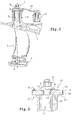
- a portion of turbomachine includes a carrier stator housing 1 vanes 2 fixed but orientable by pivots 3, located at the outer ends of the blades 2 and in bearings 4 passing through the casing 1; the extremities inner vanes 2 are joined by a ring 5 engaged around an inner pivot 6 and which helps keep the circular stages of the vanes 2 in place.
- the pivots 3 pass through the stator casing 1 and end at an outer end 7, a section 8 of which has a square shape. Further outside, the end 7 is threaded and receives a nut 9.
- a link 10 is articulated between the end 7 and a control ring 11 around the stator housing 1 and a short distance from the blade 2
- the control ring 11 goes around the stator casing 1, and it is rotated by known means such as jacks according to the control of the machine. It rotates the link 10 around the pivot 3, as well as the latter and the entire blade 2.
- the link 10 comprises a hole 13 of square shape at its end eyelet 17, and which includes flat faces coming to bear on the flat faces of pivot 3 to turn it.
- a spring 15 is added to the device. It is distinct from the other parts of the assembly and in particular from the connecting rod 10 and the pivot 3, and it consists of a washer 16 placed on the eyelet 17 of the connecting rod 10 and a flange 18 substantially at right angles. with the washer 16 which extends along a side edge face 19 of the washer 16.
- the rim 18 has a corrugation 20 oriented towards the side edge face 19 and the top of which touches it.
- a square hole 21 is formed through the washer 16.
- the proportions of the spring 15 are chosen so that the flange 18 is pushed back when the hole 21 is engaged on the square section 8 of the end of the pivot 3, even then that one of the edge faces of the bore 21 touches one of the planar faces 12 (opposite the side edge face 19) of the square section 8, and that the planar face 12 of the square section 8 which is opposite to the previous one touches the flat face 13 complementary to the eyelet 17 of the connecting rod.
- a tension is exerted on the spring 15, by which the angle of the washer 16 and the flange 18 is open relative to a free state, and it is reflected by a contact pressure between a pair of flat faces 12 and 13 of the pivot 3 and of the link 10, which lasts during all the operating states of the machine.
- the link 10 and the blade 2 remain at a fixed mutual angular position.
- All the vanes 2 of the stage controlled by the ring 11 are equipped with a similar spring 15. he may be useful to check that all springs 15 will be mounted in the same way, to avoid differences in clearance placement between hole 21 and the square section 8 of the pivot 3.
- a tab 22 to the spring 15, which is fixed to the washer 16 and directed perpendicular to it like the edge 18 already encountered, but which is not intended to be elastically deformed when the spring is placed but to provide a keying function does allowing the spring 15 to be placed only on one side.
- the tongue 22 extends along the end faces of section 23 of the rod 10 when the spring 15 has been placed correctly, but it prevents washer 16 from land on the eyelet 17 of the link 10 in the case opposite.
- the invention would be practicable with others polygonal sections of the blade pivot and the drilling of link.
Landscapes
- Engineering & Computer Science (AREA)
- Mechanical Engineering (AREA)
- General Engineering & Computer Science (AREA)
- Structures Of Non-Positive Displacement Pumps (AREA)
- Turbine Rotor Nozzle Sealing (AREA)
- Control Of Turbines (AREA)
Abstract
Description
- la figure 1 est une vue générale de l'agencement de l'invention,
- la figure 2 est une vue plus détaillée des principaux éléments de l'invention,
- et la figure 3 est une vue en éclaté de ces éléments.
Conformément à l'invention, un ressort 15 est ajouté au dispositif. Il est distinct des autres pièces de l'assemblage et notamment de la bielle 10 et du pivot 3, et il se compose d'une rondelle 16 posée sur l'oeillet 17 de la biellette 10 et d'un rebord 18 sensiblement à angle droit avec la rondelle 16 qui s'étend le long d'une face de tranche latérale 19 de la rondelle 16. Le rebord 18 présente une ondulation 20 orientée vers la face de tranche latérale 19 et dont le sommet la touche. Un perçage carré 21 est ménagé à travers la rondelle 16. De plus, les proportions du ressort 15 sont choisies pour que le rebord 18 soit repoussé quand le perçage 21 est engagé sur la section carrée 8 de l'extrémité du pivot 3, alors même que l'une des faces de bord du perçage 21 touche une des faces planes 12 (opposée à la face de tranche latérale 19) de la section carrée 8, et que la face plane 12 de la section carrée 8 qui est opposée à la précédente touche la face plane 13 complémentaire de l'oeillet 17 de biellette. En d'autres termes, une tension s'exerce sur le ressort 15, par laquelle l'angle de la rondelle 16 et du rebord 18 est ouvert par rapport à un état libre, et elle se répercute par une pression de contact entre une paire de faces planes 12 et 13 du pivot 3 et de la biellette 10, qui perdure pendant tous les états de fonctionnement de la machine. Ainsi, la biellette 10 et l'aube 2 restent à une position angulaire mutuelle fixe.
Claims (4)
- Agencement de pivotement d'aube de stator (2) dans une turbomachine, comprenant un pivot (3) de l'aube ayant une extrémité saillant hors du stator et comprenant une section (8) à faces planes, et une biellette de commande (10) engagée sur l'extrémité du pivot d'aube par un perçage limité par des faces planes (13) associées aux faces planes (12) du pivot, caractérisé en ce qu'il comprend un ressort (15) sollicité entre le pivot et la biellette et disposé de façon à presser une des faces planes du pivot contre une des faces planes de la biellette.
- Agencement de pivotement d'aube de stator suivant la revendication 1, caractérisé en ce que le ressort comprend une rondelle (16) percée posée sur la biellette et engagée autour de l'extrémité du pivot d'aube, et un rebord flexible (18) de la rondelle, engagé sur une face de tranche de la biellette qui est opposée à une des faces du pivot sur laquelle la rondelle bute, en faisant avec la rondelle un angle plus ouvert qu'à un état libre du ressort.
- Agencement de pivotement d'aube de stator suivant la revendication 2, caractérisé en ce que le ressort comprend une languette (22) engagée sur une autre face de tranche de tête de la biellette.
- Agencement de pivotement d'aube de stator suivant la revendication 2, caractérisé en ce que le rebord du ressort est engagé sur la tranche de la biellette par une ondulation (20).
Applications Claiming Priority (2)
| Application Number | Priority Date | Filing Date | Title |
|---|---|---|---|
| FR0201459A FR2835562B1 (fr) | 2002-02-07 | 2002-02-07 | Agencement de pivotement d'aube de stator dans une turbomachine |
| FR0201459 | 2002-02-07 |
Publications (2)
| Publication Number | Publication Date |
|---|---|
| EP1335112A1 true EP1335112A1 (fr) | 2003-08-13 |
| EP1335112B1 EP1335112B1 (fr) | 2006-05-03 |
Family
ID=27589602
Family Applications (1)
| Application Number | Title | Priority Date | Filing Date |
|---|---|---|---|
| EP03290287A Expired - Lifetime EP1335112B1 (fr) | 2002-02-07 | 2003-02-05 | Agencement de pivotement d'aube de stator dans une turbomachine |
Country Status (9)
| Country | Link |
|---|---|
| US (1) | US6799945B2 (fr) |
| EP (1) | EP1335112B1 (fr) |
| JP (1) | JP4050158B2 (fr) |
| CA (1) | CA2418356C (fr) |
| DE (1) | DE60304908T2 (fr) |
| ES (1) | ES2261886T3 (fr) |
| FR (1) | FR2835562B1 (fr) |
| RU (1) | RU2315869C2 (fr) |
| UA (1) | UA76114C2 (fr) |
Cited By (3)
| Publication number | Priority date | Publication date | Assignee | Title |
|---|---|---|---|---|
| GB2412947A (en) * | 2004-04-07 | 2005-10-12 | Rolls Royce Plc | Variable stator vane connection |
| EP2481891A3 (fr) * | 2011-02-01 | 2013-12-18 | United Technologies Corporation | Ecarteur d'anneau de synchronisation de turbine à gaz |
| EP3431718A1 (fr) * | 2017-07-19 | 2019-01-23 | Rolls-Royce plc | Ensemble de bague commune |
Families Citing this family (25)
| Publication number | Priority date | Publication date | Assignee | Title |
|---|---|---|---|---|
| FR2854648B1 (fr) * | 2003-05-07 | 2005-07-15 | Snecma Moteurs | Fixation avec rattrapage de jeu d'un levier de commande sur des aubes a angle de calage variable |
| GB2402180B (en) * | 2003-05-30 | 2006-09-20 | Rolls Royce Plc | Variable stator vane actuating levers |
| FR2866058B1 (fr) * | 2004-02-05 | 2006-06-02 | Snecma Moteurs | Levier de commande du calage angulaire d'une aube dans une turbomachine |
| FR2877059B1 (fr) * | 2004-10-27 | 2007-02-02 | Snecma Moteurs Sa | Biellette de commande destinee a l'entrainement d'une aube a calage variable |
| GB0505147D0 (en) * | 2005-03-12 | 2005-04-20 | Rolls Royce Plc | Securing arrangement |
| US7588415B2 (en) * | 2005-07-20 | 2009-09-15 | United Technologies Corporation | Synch ring variable vane synchronizing mechanism for inner diameter vane shroud |
| US7628579B2 (en) * | 2005-07-20 | 2009-12-08 | United Technologies Corporation | Gear train variable vane synchronizing mechanism for inner diameter vane shroud |
| US7753647B2 (en) * | 2005-07-20 | 2010-07-13 | United Technologies Corporation | Lightweight cast inner diameter vane shroud for variable stator vanes |
| US7690889B2 (en) * | 2005-07-20 | 2010-04-06 | United Technologies Corporation | Inner diameter variable vane actuation mechanism |
| US8172517B2 (en) * | 2006-12-19 | 2012-05-08 | Rolls-Royce North American Technologies, Inc. | Passive guide vane control |
| US9353643B2 (en) * | 2007-04-10 | 2016-05-31 | United Technologies Corporation | Variable stator vane assembly for a turbine engine |
| JP5256977B2 (ja) * | 2008-10-03 | 2013-08-07 | 株式会社Ihi | ターボチャージャ |
| US8414248B2 (en) | 2008-12-30 | 2013-04-09 | Rolls-Royce Corporation | Variable geometry vane |
| DE102009047006A1 (de) * | 2009-11-23 | 2011-05-26 | Robert Bosch Gmbh | Aufladeeinrichtung |
| US10208618B2 (en) * | 2013-02-04 | 2019-02-19 | United Technologies Corporation | Vane arm having a claw |
| EP3036407B1 (fr) | 2013-08-22 | 2020-11-11 | United Technologies Corporation | Ensemble à bras pour ailette |
| DE102014223975A1 (de) * | 2014-11-25 | 2016-05-25 | MTU Aero Engines AG | Leitschaufelkranz und Strömungsmaschine |
| US10370231B2 (en) | 2015-07-01 | 2019-08-06 | Big Hat Investments, LLC | Vehicle mounted fork lift and method |
| US10815818B2 (en) * | 2017-07-18 | 2020-10-27 | Raytheon Technologies Corporation | Variable-pitch vane assembly |
| DE102017222209A1 (de) * | 2017-12-07 | 2019-06-13 | MTU Aero Engines AG | Leitschaufelanbindung sowie Strömungsmaschine |
| US11008879B2 (en) | 2019-01-18 | 2021-05-18 | Raytheon Technologies Corporation | Continuous wedge vane arm with failsafe retention clip |
| US10837309B2 (en) | 2019-04-09 | 2020-11-17 | Raytheon Technologies Corporation | Retention clip for variable vane arm |
| US11391174B2 (en) | 2019-09-17 | 2022-07-19 | Raytheon Technologies Corporation | Vane arm clip for variable stator vanes |
| US20210254557A1 (en) * | 2020-02-13 | 2021-08-19 | Honeywell International Inc. | Variable vane system for turbomachine with linkage having tapered receiving aperture for unison ring pin |
| US11680494B2 (en) * | 2020-02-14 | 2023-06-20 | Raytheon Technologies Corporation | Vane arm torque transfer plate |
Citations (7)
| Publication number | Priority date | Publication date | Assignee | Title |
|---|---|---|---|---|
| DE2029859A1 (de) * | 1970-06-18 | 1972-02-03 | Motoren Turbinen Union | Verstell Leitapparat fur Turbomaschi nen |
| US4668165A (en) * | 1986-03-27 | 1987-05-26 | The United States Of America As Represented By The Secretary Of The Air Force | Super gripper variable vane arm |
| US4767264A (en) * | 1986-10-31 | 1988-08-30 | United Technologies Corporation | Vane lever arm construction |
| US5024580A (en) * | 1989-06-17 | 1991-06-18 | Rolls-Royce Plc | Control of variable stator vanes |
| US5211537A (en) * | 1992-03-02 | 1993-05-18 | United Technologies Corporation | Compressor vane lock |
| EP0545656A1 (fr) * | 1991-12-02 | 1993-06-09 | General Electric Company | Montage d'aubage statorique à calage variable pour compresseur axial de turbine à gaz |
| EP1156227A2 (fr) * | 2000-05-19 | 2001-11-21 | Mitsubishi Heavy Industries, Ltd. | Mécanisme de réglage pour les aubes variables d'une turbine à capacité variable |
Family Cites Families (7)
| Publication number | Priority date | Publication date | Assignee | Title |
|---|---|---|---|---|
| US3471126A (en) * | 1966-10-31 | 1969-10-07 | United Aircraft Corp | Movable vane unit |
| US4363600A (en) * | 1981-04-06 | 1982-12-14 | General Motors Corporation | Variable vane mounting |
| FR2524934B1 (fr) * | 1982-04-08 | 1986-12-26 | Snecma | Dispositif de butee de securite pour pivot d'aubes de stator a calage variable |
| RU2038487C1 (ru) * | 1992-06-15 | 1995-06-27 | Акционерное общество открытого типа "Авиадвигатель" | Статор многоступенчатой турбины |
| US5492446A (en) * | 1994-12-15 | 1996-02-20 | General Electric Company | Self-aligning variable stator vane |
| US6019574A (en) * | 1998-08-13 | 2000-02-01 | General Electric Company | Mismatch proof variable stator vane |
| FR2784711B1 (fr) * | 1998-10-16 | 2001-01-05 | Techlam | Dispositif de commande d'aubes a angle de calage variable |
-
2002
- 2002-02-07 FR FR0201459A patent/FR2835562B1/fr not_active Expired - Fee Related
-
2003
- 2003-01-23 JP JP2003014870A patent/JP4050158B2/ja not_active Expired - Lifetime
- 2003-01-31 US US10/354,971 patent/US6799945B2/en not_active Expired - Lifetime
- 2003-02-04 CA CA002418356A patent/CA2418356C/fr not_active Expired - Lifetime
- 2003-02-05 ES ES03290287T patent/ES2261886T3/es not_active Expired - Lifetime
- 2003-02-05 EP EP03290287A patent/EP1335112B1/fr not_active Expired - Lifetime
- 2003-02-05 DE DE60304908T patent/DE60304908T2/de not_active Expired - Lifetime
- 2003-02-06 RU RU2003103609/06A patent/RU2315869C2/ru active
- 2003-02-06 UA UA2003021093A patent/UA76114C2/uk unknown
Patent Citations (7)
| Publication number | Priority date | Publication date | Assignee | Title |
|---|---|---|---|---|
| DE2029859A1 (de) * | 1970-06-18 | 1972-02-03 | Motoren Turbinen Union | Verstell Leitapparat fur Turbomaschi nen |
| US4668165A (en) * | 1986-03-27 | 1987-05-26 | The United States Of America As Represented By The Secretary Of The Air Force | Super gripper variable vane arm |
| US4767264A (en) * | 1986-10-31 | 1988-08-30 | United Technologies Corporation | Vane lever arm construction |
| US5024580A (en) * | 1989-06-17 | 1991-06-18 | Rolls-Royce Plc | Control of variable stator vanes |
| EP0545656A1 (fr) * | 1991-12-02 | 1993-06-09 | General Electric Company | Montage d'aubage statorique à calage variable pour compresseur axial de turbine à gaz |
| US5211537A (en) * | 1992-03-02 | 1993-05-18 | United Technologies Corporation | Compressor vane lock |
| EP1156227A2 (fr) * | 2000-05-19 | 2001-11-21 | Mitsubishi Heavy Industries, Ltd. | Mécanisme de réglage pour les aubes variables d'une turbine à capacité variable |
Cited By (6)
| Publication number | Priority date | Publication date | Assignee | Title |
|---|---|---|---|---|
| GB2412947A (en) * | 2004-04-07 | 2005-10-12 | Rolls Royce Plc | Variable stator vane connection |
| GB2412947B (en) * | 2004-04-07 | 2006-06-14 | Rolls Royce Plc | Variable stator vane assemblies |
| US7344355B2 (en) | 2004-04-07 | 2008-03-18 | Rolls-Royce Plc | Variable stator vane assemblies |
| EP2481891A3 (fr) * | 2011-02-01 | 2013-12-18 | United Technologies Corporation | Ecarteur d'anneau de synchronisation de turbine à gaz |
| EP2824286A1 (fr) * | 2011-02-01 | 2015-01-14 | United Technologies Corporation | Butée d'anneau de synchronisation de moteur à turbine à gaz |
| EP3431718A1 (fr) * | 2017-07-19 | 2019-01-23 | Rolls-Royce plc | Ensemble de bague commune |
Also Published As
| Publication number | Publication date |
|---|---|
| DE60304908T2 (de) | 2006-12-21 |
| UA76114C2 (uk) | 2006-07-17 |
| US6799945B2 (en) | 2004-10-05 |
| DE60304908D1 (de) | 2006-06-08 |
| JP2003239899A (ja) | 2003-08-27 |
| US20030147743A1 (en) | 2003-08-07 |
| ES2261886T3 (es) | 2006-11-16 |
| JP4050158B2 (ja) | 2008-02-20 |
| CA2418356C (fr) | 2009-12-15 |
| EP1335112B1 (fr) | 2006-05-03 |
| CA2418356A1 (fr) | 2003-08-07 |
| FR2835562B1 (fr) | 2004-07-16 |
| RU2315869C2 (ru) | 2008-01-27 |
| FR2835562A1 (fr) | 2003-08-08 |
Similar Documents
| Publication | Publication Date | Title |
|---|---|---|
| EP1335112B1 (fr) | Agencement de pivotement d'aube de stator dans une turbomachine | |
| EP1567097B1 (fr) | Cage intervertebrale a lame d'ancrage mediane | |
| FR2742220A1 (fr) | Appareil pour deplier et fixer les ailettes d'un engin | |
| FR2916910A1 (fr) | Dispositif pour le verrouillage d'un dispositif connecteur et outil associe | |
| FR2511165A1 (fr) | Pendule offrant plusieurs modes d'utilisation | |
| EP3667431A1 (fr) | Mobile d'affichage d'horlogerie avec mecanisme de reglage de la friction | |
| FR2853930A1 (fr) | Dispositif de commande d'aubes a calage variable dans une turbomachine | |
| EP2110719A1 (fr) | Amortisseur de choc pour masse oscillante | |
| FR2537533A1 (fr) | Organe de reglage de l'intervalle entre les patins de freins pour frein a machoire | |
| EP1855011A1 (fr) | Ensemble pour compresseur de moteur d'aéronef comprenant des aubes à attache marteau à pied incline | |
| FR2824362A1 (fr) | Agencement de montage de deux lignes d'arbre coaxiales | |
| FR3068171B1 (fr) | Dispositif de fixation pour organe de commande et/ou de signalisation electrique | |
| FR2463871A1 (fr) | Dispositif de surete a goupille pour empecher le deplacement relatif d'au moins deux pieces | |
| FR2803638A3 (fr) | Structures de palier pour un rotor de moteur | |
| EP2407832A1 (fr) | Mouvement de pièce d'horologerie | |
| CH711681A2 (fr) | Guidage flexible en pivotement de mobile horloger. | |
| EP1475517A1 (fr) | Fixation avec rattrapage de jeu d'un levier de commande sur des aubes a angle de calage variable | |
| FR2736384A1 (fr) | Dispositif de montage de pic de coupe, pic de coupe et boite a pic, notamment pour machine d'exploitation de mine | |
| EP0780922A1 (fr) | Pièce anti-rotation pour cosse de connexion électrique et assemblage soudé de cette pièce et d'un élément quelconque | |
| FR2707516A1 (fr) | Jouet avec moyens de fixation et d'entraînement perfectionnés. | |
| EP2146661B1 (fr) | Dispositif de rétention axiale d'une queue d'instrument dentaire comportant un axe traversé par au moins un goupille de blocage | |
| FR2973527A1 (fr) | Rappel au neutre par double ressort | |
| FR2796774A1 (fr) | Griffe de prolongement a ressort de verrouillage sur une griffe d'origine de mecanisme electrique | |
| FR3069012A1 (fr) | Aube fixe de turbomachine, pourvue d'une plate-forme fixee au stator | |
| EP3650953B1 (fr) | Mecanisme horloger comprenant une etoile et un ressort-sautoir |
Legal Events
| Date | Code | Title | Description |
|---|---|---|---|
| PUAI | Public reference made under article 153(3) epc to a published international application that has entered the european phase |
Free format text: ORIGINAL CODE: 0009012 |
|
| AK | Designated contracting states |
Designated state(s): AT BE BG CH CY CZ DE DK EE ES FI FR GB GR HU IE IT LI LU MC NL PT SE SI SK TR |
|
| AX | Request for extension of the european patent |
Extension state: AL LT LV MK RO |
|
| 17P | Request for examination filed |
Effective date: 20040115 |
|
| AKX | Designation fees paid |
Designated state(s): DE ES FR GB IT SE |
|
| RAP1 | Party data changed (applicant data changed or rights of an application transferred) |
Owner name: SNECMA |
|
| GRAP | Despatch of communication of intention to grant a patent |
Free format text: ORIGINAL CODE: EPIDOSNIGR1 |
|
| GRAS | Grant fee paid |
Free format text: ORIGINAL CODE: EPIDOSNIGR3 |
|
| GRAA | (expected) grant |
Free format text: ORIGINAL CODE: 0009210 |
|
| AK | Designated contracting states |
Kind code of ref document: B1 Designated state(s): DE ES FR GB IT SE |
|
| PG25 | Lapsed in a contracting state [announced via postgrant information from national office to epo] |
Ref country code: IT Free format text: LAPSE BECAUSE OF FAILURE TO SUBMIT A TRANSLATION OF THE DESCRIPTION OR TO PAY THE FEE WITHIN THE PRESCRIBED TIME-LIMIT;WARNING: LAPSES OF ITALIAN PATENTS WITH EFFECTIVE DATE BEFORE 2007 MAY HAVE OCCURRED AT ANY TIME BEFORE 2007. THE CORRECT EFFECTIVE DATE MAY BE DIFFERENT FROM THE ONE RECORDED. Effective date: 20060503 |
|
| REG | Reference to a national code |
Ref country code: GB Ref legal event code: FG4D Free format text: NOT ENGLISH |
|
| REF | Corresponds to: |
Ref document number: 60304908 Country of ref document: DE Date of ref document: 20060608 Kind code of ref document: P |
|
| GBT | Gb: translation of ep patent filed (gb section 77(6)(a)/1977) |
Effective date: 20060607 |
|
| REG | Reference to a national code |
Ref country code: SE Ref legal event code: TRGR |
|
| REG | Reference to a national code |
Ref country code: ES Ref legal event code: FG2A Ref document number: 2261886 Country of ref document: ES Kind code of ref document: T3 |
|
| PLBE | No opposition filed within time limit |
Free format text: ORIGINAL CODE: 0009261 |
|
| STAA | Information on the status of an ep patent application or granted ep patent |
Free format text: STATUS: NO OPPOSITION FILED WITHIN TIME LIMIT |
|
| 26N | No opposition filed |
Effective date: 20070206 |
|
| PGFP | Annual fee paid to national office [announced via postgrant information from national office to epo] |
Ref country code: ES Payment date: 20130207 Year of fee payment: 11 |
|
| REG | Reference to a national code |
Ref country code: ES Ref legal event code: FD2A Effective date: 20150731 |
|
| PG25 | Lapsed in a contracting state [announced via postgrant information from national office to epo] |
Ref country code: ES Free format text: LAPSE BECAUSE OF NON-PAYMENT OF DUE FEES Effective date: 20140206 |
|
| REG | Reference to a national code |
Ref country code: FR Ref legal event code: PLFP Year of fee payment: 14 |
|
| REG | Reference to a national code |
Ref country code: FR Ref legal event code: PLFP Year of fee payment: 15 |
|
| REG | Reference to a national code |
Ref country code: FR Ref legal event code: PLFP Year of fee payment: 16 |
|
| REG | Reference to a national code |
Ref country code: FR Ref legal event code: CD Owner name: SAFRAN AIRCRAFT ENGINES Effective date: 20170719 |
|
| PGFP | Annual fee paid to national office [announced via postgrant information from national office to epo] |
Ref country code: GB Payment date: 20220124 Year of fee payment: 20 Ref country code: DE Payment date: 20220119 Year of fee payment: 20 |
|
| PGFP | Annual fee paid to national office [announced via postgrant information from national office to epo] |
Ref country code: SE Payment date: 20220120 Year of fee payment: 20 Ref country code: IT Payment date: 20220119 Year of fee payment: 20 Ref country code: FR Payment date: 20220119 Year of fee payment: 20 |
|
| REG | Reference to a national code |
Ref country code: DE Ref legal event code: R071 Ref document number: 60304908 Country of ref document: DE |
|
| REG | Reference to a national code |
Ref country code: GB Ref legal event code: PE20 Expiry date: 20230204 |
|
| REG | Reference to a national code |
Ref country code: SE Ref legal event code: EUG |
|
| PG25 | Lapsed in a contracting state [announced via postgrant information from national office to epo] |
Ref country code: GB Free format text: LAPSE BECAUSE OF EXPIRATION OF PROTECTION Effective date: 20230204 |