EP1333203A2 - Sperreinrichtung - Google Patents
Sperreinrichtung Download PDFInfo
- Publication number
- EP1333203A2 EP1333203A2 EP02027349A EP02027349A EP1333203A2 EP 1333203 A2 EP1333203 A2 EP 1333203A2 EP 02027349 A EP02027349 A EP 02027349A EP 02027349 A EP02027349 A EP 02027349A EP 1333203 A2 EP1333203 A2 EP 1333203A2
- Authority
- EP
- European Patent Office
- Prior art keywords
- shift
- finger
- locking
- rail
- engages
- Prior art date
- Legal status (The legal status is an assumption and is not a legal conclusion. Google has not performed a legal analysis and makes no representation as to the accuracy of the status listed.)
- Granted
Links
- 239000002184 metal Substances 0.000 claims description 6
- 230000000903 blocking effect Effects 0.000 claims 1
- 230000007935 neutral effect Effects 0.000 description 23
- 230000033001 locomotion Effects 0.000 description 20
- 238000006073 displacement reaction Methods 0.000 description 5
- 230000001174 ascending effect Effects 0.000 description 3
- 210000003746 feather Anatomy 0.000 description 3
- 230000006835 compression Effects 0.000 description 2
- 238000007906 compression Methods 0.000 description 2
- 238000010586 diagram Methods 0.000 description 2
- 238000000034 method Methods 0.000 description 2
- 230000005540 biological transmission Effects 0.000 description 1
- 230000001419 dependent effect Effects 0.000 description 1
- 210000003128 head Anatomy 0.000 description 1
- 239000000463 material Substances 0.000 description 1
- 238000005096 rolling process Methods 0.000 description 1
Images



Classifications
-
- F—MECHANICAL ENGINEERING; LIGHTING; HEATING; WEAPONS; BLASTING
- F16—ENGINEERING ELEMENTS AND UNITS; GENERAL MEASURES FOR PRODUCING AND MAINTAINING EFFECTIVE FUNCTIONING OF MACHINES OR INSTALLATIONS; THERMAL INSULATION IN GENERAL
- F16H—GEARING
- F16H63/00—Control outputs from the control unit to change-speed- or reversing-gearings for conveying rotary motion or to other devices than the final output mechanism
- F16H63/02—Final output mechanisms therefor; Actuating means for the final output mechanisms
- F16H63/30—Constructional features of the final output mechanisms
- F16H63/34—Locking or disabling mechanisms
- F16H63/3408—Locking or disabling mechanisms the locking mechanism being moved by the final actuating mechanism
-
- F—MECHANICAL ENGINEERING; LIGHTING; HEATING; WEAPONS; BLASTING
- F16—ENGINEERING ELEMENTS AND UNITS; GENERAL MEASURES FOR PRODUCING AND MAINTAINING EFFECTIVE FUNCTIONING OF MACHINES OR INSTALLATIONS; THERMAL INSULATION IN GENERAL
- F16H—GEARING
- F16H59/00—Control inputs to control units of change-speed- or reversing-gearings for conveying rotary motion
- F16H59/02—Selector apparatus
- F16H59/04—Ratio selector apparatus
- F16H59/042—Ratio selector apparatus comprising a final actuating mechanism
-
- F—MECHANICAL ENGINEERING; LIGHTING; HEATING; WEAPONS; BLASTING
- F16—ENGINEERING ELEMENTS AND UNITS; GENERAL MEASURES FOR PRODUCING AND MAINTAINING EFFECTIVE FUNCTIONING OF MACHINES OR INSTALLATIONS; THERMAL INSULATION IN GENERAL
- F16H—GEARING
- F16H63/00—Control outputs from the control unit to change-speed- or reversing-gearings for conveying rotary motion or to other devices than the final output mechanism
- F16H63/02—Final output mechanisms therefor; Actuating means for the final output mechanisms
- F16H63/30—Constructional features of the final output mechanisms
- F16H63/34—Locking or disabling mechanisms
- F16H63/36—Interlocking devices
-
- F—MECHANICAL ENGINEERING; LIGHTING; HEATING; WEAPONS; BLASTING
- F16—ENGINEERING ELEMENTS AND UNITS; GENERAL MEASURES FOR PRODUCING AND MAINTAINING EFFECTIVE FUNCTIONING OF MACHINES OR INSTALLATIONS; THERMAL INSULATION IN GENERAL
- F16H—GEARING
- F16H59/00—Control inputs to control units of change-speed- or reversing-gearings for conveying rotary motion
- F16H59/02—Selector apparatus
- F16H2059/026—Details or special features of the selector casing or lever support
- F16H2059/0265—Selector lever support with pivot axis offset, e.g. support by four bar linkage to create pivoting centre outside the mechanism
-
- F—MECHANICAL ENGINEERING; LIGHTING; HEATING; WEAPONS; BLASTING
- F16—ENGINEERING ELEMENTS AND UNITS; GENERAL MEASURES FOR PRODUCING AND MAINTAINING EFFECTIVE FUNCTIONING OF MACHINES OR INSTALLATIONS; THERMAL INSULATION IN GENERAL
- F16H—GEARING
- F16H63/00—Control outputs from the control unit to change-speed- or reversing-gearings for conveying rotary motion or to other devices than the final output mechanism
- F16H63/02—Final output mechanisms therefor; Actuating means for the final output mechanisms
- F16H63/08—Multiple final output mechanisms being moved by a single common final actuating mechanism
- F16H63/20—Multiple final output mechanisms being moved by a single common final actuating mechanism with preselection and subsequent movement of each final output mechanism by movement of the final actuating mechanism in two different ways, e.g. guided by a shift gate
- F16H2063/204—Multiple final output mechanisms being moved by a single common final actuating mechanism with preselection and subsequent movement of each final output mechanism by movement of the final actuating mechanism in two different ways, e.g. guided by a shift gate the gear shift lever being the immediate final actuating mechanism, e.g. the shift finger being a part of the gear shift lever
-
- Y—GENERAL TAGGING OF NEW TECHNOLOGICAL DEVELOPMENTS; GENERAL TAGGING OF CROSS-SECTIONAL TECHNOLOGIES SPANNING OVER SEVERAL SECTIONS OF THE IPC; TECHNICAL SUBJECTS COVERED BY FORMER USPC CROSS-REFERENCE ART COLLECTIONS [XRACs] AND DIGESTS
- Y10—TECHNICAL SUBJECTS COVERED BY FORMER USPC
- Y10T—TECHNICAL SUBJECTS COVERED BY FORMER US CLASSIFICATION
- Y10T74/00—Machine element or mechanism
- Y10T74/20—Control lever and linkage systems
- Y10T74/20012—Multiple controlled elements
- Y10T74/20018—Transmission control
- Y10T74/20085—Restriction of shift, gear selection, or gear engagement
-
- Y—GENERAL TAGGING OF NEW TECHNOLOGICAL DEVELOPMENTS; GENERAL TAGGING OF CROSS-SECTIONAL TECHNOLOGIES SPANNING OVER SEVERAL SECTIONS OF THE IPC; TECHNICAL SUBJECTS COVERED BY FORMER USPC CROSS-REFERENCE ART COLLECTIONS [XRACs] AND DIGESTS
- Y10—TECHNICAL SUBJECTS COVERED BY FORMER USPC
- Y10T—TECHNICAL SUBJECTS COVERED BY FORMER US CLASSIFICATION
- Y10T74/00—Machine element or mechanism
- Y10T74/20—Control lever and linkage systems
- Y10T74/20012—Multiple controlled elements
- Y10T74/20018—Transmission control
- Y10T74/20085—Restriction of shift, gear selection, or gear engagement
- Y10T74/20104—Shift element interlock
- Y10T74/2011—Shift element interlock with detent, recess, notch, or groove
-
- Y—GENERAL TAGGING OF NEW TECHNOLOGICAL DEVELOPMENTS; GENERAL TAGGING OF CROSS-SECTIONAL TECHNOLOGIES SPANNING OVER SEVERAL SECTIONS OF THE IPC; TECHNICAL SUBJECTS COVERED BY FORMER USPC CROSS-REFERENCE ART COLLECTIONS [XRACs] AND DIGESTS
- Y10—TECHNICAL SUBJECTS COVERED BY FORMER USPC
- Y10T—TECHNICAL SUBJECTS COVERED BY FORMER US CLASSIFICATION
- Y10T74/00—Machine element or mechanism
- Y10T74/20—Control lever and linkage systems
- Y10T74/20012—Multiple controlled elements
- Y10T74/20018—Transmission control
- Y10T74/2014—Manually operated selector [e.g., remotely controlled device, lever, push button, rotary dial, etc.]
-
- Y—GENERAL TAGGING OF NEW TECHNOLOGICAL DEVELOPMENTS; GENERAL TAGGING OF CROSS-SECTIONAL TECHNOLOGIES SPANNING OVER SEVERAL SECTIONS OF THE IPC; TECHNICAL SUBJECTS COVERED BY FORMER USPC CROSS-REFERENCE ART COLLECTIONS [XRACs] AND DIGESTS
- Y10—TECHNICAL SUBJECTS COVERED BY FORMER USPC
- Y10T—TECHNICAL SUBJECTS COVERED BY FORMER US CLASSIFICATION
- Y10T74/00—Machine element or mechanism
- Y10T74/20—Control lever and linkage systems
- Y10T74/20012—Multiple controlled elements
- Y10T74/20018—Transmission control
- Y10T74/20177—Particular element [e.g., shift fork, template, etc.]
Definitions
- the invention relates to a locking device with a locking member for optional Block at least one of the first actuated by a shift finger Shift rail and a second shift rail, which is about a tilt axis swiveled shift finger can be moved into one of the positively Shift rails engages and the shift rail into which the shift finger engages by means of the shift finger pivoting about the pivot axis in at least one direction is longitudinally displaceable and wherein the first shift rail fixed longitudinally by means of the locking member to the second shift rail is when the shift finger pivoted about the tilt axis is positive engages movably in the second shift rail.
- a Shift fingers are assigned to shiftable shift rails.
- the Shift rails are individual gears of the manual transmission shiftable.
- the Shift rails are provided with engaging grooves forming shift gates, in that of the shift finger by corresponding axial displacement of a shift shaft can intervene. If the engagement grooves in one to the direction of displacement of the shift finger aligned line, the shift lever of the change gearbox stands in a neutral position in which no gear is engaged.
- the shift finger engages in one of the engagement grooves of one of the Switch rails on. By turning the selector shaft with the selector finger the shift finger swings and shifts one of the gears.
- the locking cams are located in the neutral position aligned approximately horizontally above the engagement grooves and act with fork-like elongated to the level of the locking cams Wall parts of the engagement grooves together.
- the outer circumference of the locking cams is circularly symmetrical.
- the fork-like wall parts are in the form of a circular arc adjusted of the locking cam and include the locking cam with a little play.
- the locking cams fix the shift rails in the neutral position.
- the width of the locking cams is designed to take into account of the total displacement of the shift finger each of the Shift finger associated shift rail is fixed. There is one in each of the locking cams Milled slot.
- the slots are in a common swivel plane with the shift finger.
- the width of the slots is slightly larger than the thickness every single shift rail.
- the slots are in a common Swivel level with the shift finger. After choosing the alley, the Shift finger, the slots and the wall parts of a shift rail in a common Level.
- the shift rail can be moved using the pivoting shift finger can be switched because the wall parts optionally, depending on the Direction of displacement of the shift rail, dip into the slots of the spermock.
- the depth of the slots is designed to make end stops for form the longitudinal movements of the shift rail.
- the locking device is in switching devices for switching gear wheels used by means of a shift lever.
- One or two on a gear shaft Lying optionally switchable gear wheels are each assigned to an alley.
- Several gear wheels can be switched by the switching device.
- At least one gear wheel or a maximum of two gear wheels are assigned to an alley. Each gear wheel can only be shifted in its predetermined alley.
- the shift lever can be pivoted to a housing by means of a bearing arrangement arranged.
- the bearing arrangement enables pivoting movements of the Shift lever in a selection level and in a cross-directional to the selection level Switching level.
- the shift lever is guided by a backdrop.
- the gear lever is in a neutral position in the selection level and is in the Selection level from the neutral position through the choice of alleys optionally in one of at least two rest positions can be swiveled. Is the shift lever in one of the rest positions, an alley is chosen. From the rest position the shift lever in the shift plane for shifting one of the gears into one Switch position swiveling.
- the neutral position of the shift lever is mostly also one of the rest positions, from which either one of two courses is switchable.
- the shift lever is Provide a shift finger at one free end.
- Each of the shift rails has an engagement groove or a switching mouth for the engagement of the shift finger on. Selective movements of the shift lever make an optional intervention in one of at least two axially parallel shift rails.
- the shift lever can be moved with one of the shift rails in these positions coupled.
- a pivoting of the shift lever in the shift plane from the rest position in one or the other direction has a shifting with the shift lever coupled shift rail result because the shift finger an the engagement groove limiting edge is applied.
- One assigned to the shift rail Gears are engaged by moving the shift rail.
- the shift lever is usually to a vehicle-fixed housing by means of a cardanic joint pivoted.
- This Joint or this bearing arrangement sees a box-shaped bracket in front.
- the console picks up the shift lever and is by means of the shift lever about a tilt axis aligned transversely to the swivel axis Vehicle-fixed housing pivoted.
- the tilt axis is aligned with the Center axis of either one or two rocking pins.
- the gear lever is in the selection level, in the Fixed bracket, swiveling with the bracket around the tilt axis.
- the selection movement on the shift finger is carried out by the pivoting movement about the tilt axis Shift lever the console with.
- the shift finger is on the Shift attack (shift knob) opposite side of the tilt axis on the shift lever arranged and pivots with the shift lever in the selection level Tilting axis.
- the bearing arrangement also sees a pivotable mounting of the shift lever in the switching plane around a swivel axis in the console.
- the swivel axis is transverse to the tilt axis.
- the swivel axis is simultaneous the center axis of a pivot pin arranged in the console.
- the Shift lever is around the swivel pin in the shift plane, but not in the Selection level, stored on the console.
- the shift finger is on the opposite side End of the shift lever to the pivot axis and in the shift plane, however, not in the selection level, pivotable in about the pivot axis the console stored.
- the swivel axis and the tilt axis intersect on a common level.
- Switching forces are to be understood as the forces acting on the force application by the Operator (shift knob) noticeable on the shift lever when selecting and shifting are.
- the gearshift lever engages with power when selecting and shifting defined ways back. This means that every additional point is on the lever defined by the force application and the swivel or tilt axis its distance from the axes back to given paths. The way, mostly in radians, depends on the distance between the gear knob and the axles.
- the Shift lever is often due to a between the force application and the axles located shift gate.
- the design of material and space-saving The scenes are in the scenery because of the same way of the gear lever there are often limits to dialing and switching movements.
- the switching forces on Shift knobs can be influenced via the lever ratio of the shift lever.
- the leverage ratio results from the distance from the knob to the axles and from the distance from the axes to the engagement of the shift finger in the Engaging groove of the shift rail.
- the length of the protruding into the passenger compartment Shift levers are generally limited due to the space available.
- the length of the shift finger, starting from the crossing axes is from the Location of the elements of the inner circuit adjoining the shift lever dependent.
- the swiveling shift lever is when choosing the alley and when shifting the corridors through guideways, e.g. B. a backdrop.
- the swivel movements of the shift lever in the selection and shift direction are by stops limited.
- the stops ensure that the shift finger after the Completion of selecting an alley exactly in one of the engagement grooves of one of the Shift rails engages.
- the limit the switching path of the shift finger Stops ensure that the shift rail is exactly in its specified position and is not moved beyond.
- the invention is characterized by the characterizing part of claim 1 solved that the locking member is a locking finger.
- the locking member is a locking finger.
- On each of the shift rails is one in the direction of the tilt axis and in the pivoting directions of the Tilt axis pivoted locking finger formed open slot.
- the locking finger optionally engages in one or more of the slots.
- at least a first shift rail is connected to the locking finger second shift rail fixed longitudinally when the pivoted about the tilt axis Shift finger can be positively moved into the second shift rail intervenes.
- the second shift rail is connected to the first by means of the locking finger Shift rail fixed longitudinally when the pivoted about the tilt axis Shift finger engages positively in the first shift rail.
- the about the tilt axis pivoting locking finger is in the direction of the pivot Locking fingers one behind the other and aligned slots can be swiveled until the shift finger moves into one of the selected longitudinally Shift rails and the locking finger in the slot of at least intervene positively in a shift rail to be fixed.
- the locking device is on the Bearing arrangement of the shift lever provided.
- At least two, however, mostly three or four switching rails lie side by side in the swivel range the shift finger.
- the shift rails are in a middle position when the shift lever is in the neutral position neutral position.
- the by means of the shift rail by moving the Shift rails, shiftable gears are not shifted.
- Each of the shift rails has an engagement groove or a switching mouth for engaging the Shift finger on.
- the locking finger pivots with the selector lever around the Tilting axis swiveling console and can move in its swiveling direction move freely through the adjacent slots until the shift finger in one of the selected longitudinally movable shift rails as well the locking finger in the slot or the slots of a shift rail to be fixed intervenes positively.
- the one acted upon by the shift finger Shift rail is not locked by the locking finger and is in the longitudinal direction freely movable using the shift finger.
- the Shift lever remains around the pivot axis for shifting gears Lock finger in the slots of the locked shift rails and holds them during of the switching operations and while the vehicle is in motion with the Gear in their locked position.
- An embodiment of the invention provides that the shift finger at least three of the shift rails are assigned.
- the locking finger engages in two of the Switch rails on at the same time.
- the shift finger is the one to be shifted Shift rail positively connected.
- the shift finger is up after completion of the dialing process in an alley, the one to be blocked between two Shift rails is assigned to arranged shift rails, blocks the Locking finger the neighboring shift rails at the same time.
- a franking on the locking finger ensures that the selected shift rail from the The locking finger can be swiveled freely and freely by means of the shift finger is.
- the franking is located above the slot of the freely movable shift rail.
- the locking finger does not engage in this shift rail Slit one.
- the shift rail movable with the shift finger, penetrates the Postage on the locking finger to the locking finger thus contactless.
- the locking finger is a flat sheet metal part.
- the sheet metal part is either perpendicular in an imaginary of the rocking axis of the shift lever penetrated plane in one piece with the wall from the wall of the Console or is attached to this separately.
- the locking finger is in this level so wide that in every pivoted position of the locking finger each of the shift rails to be locked using the locking finger is acted upon.
- the console is aligned by means of the shift lever about a transverse to the pivot axis Tilting axis pivotable on a housing that is fixed to the vehicle stored.
- the tilt axis aligned with the central axis of either one or two rocker bolts.
- the rocker pins support the console in the selection level, however not in the switching plane, pivotable on the housing.
- the gear lever is immovable in the dialing level, to the console, with the console around the Tilt axis swiveling. With a selection movement on the shift finger takes the shift lever swiveling around the tilt axis also supports the console.
- the shift finger is on a side pointing to the switching attack, preferably on the opposite side, the tilt axis arranged on the shift lever and swivels around the tilt axis in the selection level with the gear lever.
- the engagement grooves are in the middle neutral position of the shift rail in the selection directions in a line to each other aligned.
- the shift finger can move freely in the dialing level Swivel through the engagement grooves until the switch lever is in the rest position is reached and the shift lever engages in one of the engagement grooves.
- the bearing arrangement of the shift lever continues to see the pivotable mounting of the shift lever in the shift plane around a pivot axis in the console in front.
- the swivel axis is transverse to the tilt axis.
- the pivot axis aligns with the centers of two bearing eyes opposite each other in the console or alternatively with a bearing eye formed in the console.
- the shift lever is around one in the bearing eye (s) Swivel pin can be swiveled in the switching level, but not in the selection level stored on the console.
- the shift knob and the shift finger each have in a different direction away from the pivot axis.
- With the switching movements is the shift lever over the shift finger with one of the engagement grooves a shift rail movably coupled. The switching movement does that Moving the shift rail.
- the shift finger acts on one of the flank of the engagement groove lying in the direction of displacement of the shift rail.
- One of the gears assigned to the shift rail is shifted by Shift rail inserted.
- One embodiment of the invention provides that the tilt axis and the pivot axis of the shift lever are spaced apart.
- the pivot axis and the tilt axis lie horizontally according to the invention different and vertical, depending on the design of the bearing arrangement, in a common or at different levels.
- the swivel axis and the tilt axis lie between the force applied to the gear knob and the Shift finger. Swiveling movements around the one closest to the shift finger of the axles result on the gear knob as well as on each of the Direction of this axis at the points of the gear knob Shift lever in a longer distance in radians if the Switching device both the dialing and switching movements on one limited same swivel angle.
- the tilt bolts are rotatably received in the housing.
- the console is around the rocker bolts pivotable.
- the Tilting bolts without a separate bearing fit precisely in the bearing eye of the console.
- the shift lever can either be pivoted about the movement-fixed to the console Swivel pin mounted or the swivel pin sits firmly in the Shift lever and moves in the bearing eyes of the console.
- they are Bearings of the shift lever on the pivot pin or the bearings the pivot pin in the console with plain bearings.
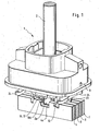
- Figure 1 shows an overall view of an embodiment of a bearing arrangement 1.
- a shift lever 2 is mounted in the bearing arrangement 1.
- the bearing arrangement 1 is accommodated in a housing 3.
- the shift lever 2 acts with a shift finger 2a optionally on shift rails 4, 5, 6 and 7.
- Die Shift rails 4, 5, 6 and 7 are each with an engagement groove 4a, 5a, 6a, 7a provided, in which the shift lever 2 depending on its selection position intervenes.
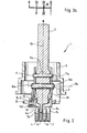
- the bearing assembly 1 is shown in section.
- the shift lever 2 is in the neutral position N.
- the shift finger 2a runs slightly to that in the The neutral position of the center axis 2b of the shift finger 2 is angled and engages in the engagement groove 5a of the shift rail 5.
- the shift rails 4, 5, 6 and 7 are in a neutral middle position. In this neutral middle position are the engagement grooves 4a, 5a, 6a and 7a in the pivoting direction of the shift lever 2 aligned one behind the other and to each other.
- the shift lever 2 is from the neutral position N about the tilt axis perpendicular to the illustration 9a pivotally arranged in the bearing arrangement 1.
- the shift finger 2a is within the when the switching lever 2 is pivoted about the tilt axis 2a Engagement grooves 4a, 5, 6a and 7a freely pivotable.
- the shift lever 2 is in a bracket 10 on a pivot pin 8 about the pivot axis 8a pivoted.
- the pivot pin 8 is firmly seated in the bearing eyes 10a Console 10.
- a stop 11 in the form of a Attached to the pin. With the stop 11, the pivot angle of the shift lever 2 around the pivot axis 8a in a direction extending in the pivoting direction Elongated hole 11a limited (see also Figure 7).
- the shift lever 2 is about the pivot axis 8a swiveling with the shift finger 2a.
- the shift finger 2a acts on it a flank of the engagement groove 5a lying in the pivoting direction.
- the shift rail 5 is assigned to an alley from which the third and fourth gear through Swiveling the shift lever 2 are switchable.
- Figure 2a shows the circuit diagram to the selection or switching positions of the shift knob 2c. From the alley III-IV is the shift lever 2 about the tilt axis 9a in the direction of the lane I-II pivotable. In the alley I-II, the shift finger 2a engages in the shift rail 4 on. With the shift rail 4 is the first or second gear by means of the Swivel axis 8a pivoting shift lever 2 switchable.
- either fourth or fifth gear can be shifted.
- the shift lever about the tilt axis 9a beyond the alley VI-V the alley of reverse gear R is selected.
- the shift finger 2a engages thereby in the engagement groove 7a of the shift rail 7.
- By swiveling the Shift lever 2 about the pivot axis 8a is the reverse gear from this Switchable position.
- Figure 5 shows the same section as in Figure 2.
- the shift lever 2 is by pivoting about the tilt axis 9a into the alley of the reverse gear R moves.
- the shift finger 2a engages in the engagement groove 7a of the shift rail 7 a. From this position, the shift lever 2 is about the pivot axis 8a swiveling.
- the shift finger 2a pivoting with the shift lever 2 takes the shift rail 7 in its longitudinal direction until the reverse gear R is inserted.
- FIG. 3 shows a cross section of the bearing assembly 1.
- the shift lever 2 is in the neutral position and engages with the shift finger 2a in the shift rail 5 a.
- the shift rail 4 is through the shift rail 5 covered.
- the shift finger is form-fitting via the engagement in the engagement groove 5a coupled to the shift rail 5.
- From the neutral position is the Shift lever 2 pivotable about the tilt axis 9a and the pivot axis 8a.
- the tilt axis 9a is the center line of two tilt pins 9.
- the tilt pins 9 are fixed in the housing 3 and each engage in a bearing eye 10b of the console 10.
- the console 10 is through the shift lever 2 by means of plain bearings 13 stored in the bearing eye 10b on the tilt pin 9.
- the pivot axis 8a and the tilt axis 9a run at a distance A from one another spaced apart and across.
- the pivot axis 8a is located here closest to the shift finger 2a.
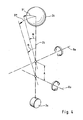
- FIG 4 a schematic representation of the shift lever 2 with the axes 8a, 9a shows that by means of the spaced apart by the distance A.
- Axes 8a, 9a different selection and switching paths on the shift knob 2c des Shift lever can be achieved.
- the shift knob 2c puts one around the tilt axis 9a with the swivel angle ⁇ swiveled shift lever 2 the way B ' back in radians. If the shift lever 2 with the pivot axis 8a the same angle ⁇ is pivoted, the shift knob 2c sets the path B " back in radians. B "is due to the distance A between the axis 8a and the axis 9a larger than B '.
- FIG. 6 shows the bearing arrangement 1 in the same sectional view as in FIG Figure 3.
- the shift lever 2a is about the pivot axis 8a in a switching position pivoted and has the shift rail 5 in by means of the shift finger 2a their longitudinal direction shifted.
- the shift rail 4 remains unchanged in their position.
- the shift rail 4 is by means of a Locking finger 12 set on the console 10.
- the locking finger 12 engages in this a slot 4b on the shift rail 4.
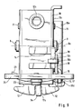
- the locking finger 12 in a front view at least partially shown.
- the locking finger 12 is by means of a franking 12a shared. Through the franking 12a is the shift rail 5 in the arrangement shown in FIG. 6 without contact to the Shift finger 12 slidable therethrough. As can be seen from the view in FIG.
- the locking finger 12 pivots with the shift finger about the tilt axis 9a, if one of the alleys is selected with the shift lever 2.
- the Lock finger 12 by means of the franking 12a, the shift rail 7 for the Switching the reverse gear and in Figure 6, the shift rail 5 for the Unlock one of the gears assigned to the shift rail 5.
- Figure 9 shows the Console 10 with the locking finger 12 without the shift rails.
- the shift finger 2a can be pivoted in the direction of the franking 12a about the pivot axis 8a, so that each of the shift rails engaged with the shift finger 2a closes the locking finger 12 can be moved contactlessly by the franking 12a is.
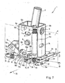
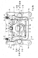
- FIG. 7 shows the bearing arrangement 1 without the housing 3.
- the bracket 10 is made from a profile or bent from a sheet metal into a profile.
- the Bracket slots 11a and 14 are introduced. Engages in slot 11a, as already described at the beginning, the stop 11.
- the stop 11 goes from the shift lever 2.
- the stop 11 is located at one end of the elongated hole 11a on when a gear is engaged.
- the pivoting movement of the console 10 is closed limited the housing around the tilt pin 9.
- the bearing arrangement 1 has a locking contour 15 with locking recesses 15a, 15b and 15c.
- the locking contour 15 is formed from sheet metal. The sheet is angular bent and by means of an outgoing from the locking contour 15 Extension 15d attached to the shift lever 2.
- the extension 15d passes through a penetrated by the pivot axis 8a of the shift lever 2 Wall 10c of console 10 at an opening 10d of the wall.
- the locking element 16 is a roller 17.
- the roller 17 is rotatably seated on a pin 17a.
- the bolt 17a is attached to a rocker arm 18.
- the rocker arm 18 is around the tipping point 18a pivotally mounted on a pin 18b.
- the pin 18b is on one with the tilt axis 9a rectified and from the axis of rotation of the roller 17 pioneering projection 19 attached.
- the rocker arm 18 is formed from sheet metal and has a hook-shaped end 18c.
- the hook-shaped end 18c engages behind the projection 19 on a side facing away from the rocker arm 18 Page. So that the rocker arm 18 on the pin 18b is axially on the projection 19 secured.
- the one which is movably mounted on the rocker arm 18 about its axis of rotation Roller 17 is attached to the by means of a further hook-shaped end 18d Rocker arm 18 secured.
- the hook-shaped end 18d engages behind the Roller 17 on a side facing away from the rocker arm 18.
- the rocker arm 18 is at one end facing away from the tilt point 18a Spring 20 loaded.
- the spring 20 is a tension spring and is her one End on the rocker arm 18 and the other end on the console 10 hooked.
- the spring 20 pulls the rocker arm 18 with the roller 17 against the Locking contour 15 and is guided in a sleeve 10e on the console 10.
- the Shift lever 2 is in Figure 7, pivoted about the pivot axis 8a in one switched position.
- the stop 11 lies at one end of the elongated hole 11a. In this position, the roller 17 is locked in the locking recess 15c and locks the shift lever 2 in its position.
- the shift lever 2 turns in opposite directions pivoted to its current pivot position about the pivot axis 8a, the roller 17 rises from the locking recess 15c and initially locks in the recess 15b.
- the shift lever 2 is in this position either in the neutral position or in one of the rest positions of the alleys before shifting a gear. If the locking lever 2 continues in this direction pivoted, the roller 17 finally locks in the locking recess 15a and locks the shift lever 2 in another shift position.
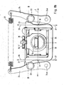
- the bearing arrangement 1 has a device for increasing selection forces on. As can be seen from FIGS. 8a and 8b, the device is off two ramps 21, one biased against the ramp by means of a spring 22 Drain roller 23 and two levers 24 are formed.
- the ramps 21 are formed on a bow-shaped sheet 25.
- the sheet 25 is on the console 10 attached.
- the levers 24 are each around a housing, not shown fixed pivot point 24a in the direction of the console 10 pivotally arranged.
- Each of the drain rollers 23 is rotatably arranged on one of the levers 24.
- the tension spring 22 is at one of its ends at one to the fulcrum 24a opposite end of the lever 24 hooked.
- the levers 24 are biased against each other and thus against the bracket 10 by means of the tension spring.
- One of the rollers 23 is pressed against the lever 24 one of the ramps 21 pulled.
- the ramps 21 are divided into sections of different ascents and have the same ramp contour to each other.
- the contour of everyone Ramp 21 rises over two abscissas pointing in opposite directions 26, 27 starting from a coordinate origin U.
- the abscissas 26 and 27 go transversely from an imaginary plane E and are therefore parallel to Swivel axis 8a of the shift lever 2 aligned ( Figure 7, Figure 8a, Figure 8b).
- the plane E runs with the tilt axis 9a of the shift lever 2 and is penetrated at right angles by the pivot axis 8a of the shift lever 2.
- the Coordinate origin U lies in the plane E.
- a pivoted about the tilt axis 9a Shift lever 2 pivots the console 10 against the ramp 21 the fixed roller in the pivoting direction 23.
- the contour of the ramps 21 moves in the pivoting direction to the axis of rotation of the drain roller 23, whereby the biased against the ramp 21 respective roller 23 on the ramp 21 rolls ascending.
- the one aligned perpendicular to the abscissa 26 and 27 Ordinate 28 runs parallel to the tilt axis 9a with the plane E.
- a roller 23 is centered on a ramp 21 in the neutral position N of the shift lever at the coordinate origin U.
- the ramp 21 initially runs over the abscissa 26 as well as over the abscissa 27 increasing gently.
- the ascending at the sections with the flat rise Drain rollers 23 produce on the for selecting an alley with forward gears pivoted shift lever 2 a relatively low selection force.
- the drain rollers 23 each remain in one of the positions marked with I-II or V-VI on the respective Ramp 21.
- shift lever 2 is in one of the alleys I-II or V-VI, from which then in the respective alley by swiveling the Shift finger 2 a gear is switchable.
- the gear lever 2 is about to enter the alley for shifting into reverse gear R. move.
- the steep rise on ramp 21 finally follows into position R a flat rise again.
- the drain roller 23 is in the R position the alley of reverse gear R selected. This position is in Figure 8b shown graphically. From position R, the shift lever 2 is around the Swivel axis 8a for switching the reverse gear R swivel.
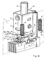
- FIG 10 shows a further embodiment of a bearing arrangement according to the invention.
- the bearing arrangement 29 is shown without a housing. Your structure corresponds essentially to the bearing arrangement 1 according to FIGS. 1 to 9. However, its structure differs from the arrangement of the device to increase the dialing power.
- the bearing arrangement 29 has two ramps 30, one of which is illustrated and the other one Console 31 is covered.
- the ramp 30 rises as in the aforementioned example over two abscissas 32 and 33 pointing in opposite directions.
- the abscissa is at right angles from an imaginary one with the tilt axis 34 of the shift lever 35 and perpendicular to the pivot axis 36 of the shift lever 35 penetrated plane F.
- the coordinate origin V of the coordinate system lies in the plane F.
Landscapes
- Engineering & Computer Science (AREA)
- General Engineering & Computer Science (AREA)
- Mechanical Engineering (AREA)
- Arrangement Or Mounting Of Control Devices For Change-Speed Gearing (AREA)
- Lock And Its Accessories (AREA)
- Gear-Shifting Mechanisms (AREA)
Abstract
Description
- Figur 1
- eine Gesamtansicht der Lageranordnung,
- Figur 2
- einen Längsschnitt durch die Lageranordnung,
- Figur 2a
- das Schaltschema der Stellungen des Schalthebels,
- Figur 3
- einen Querschnitt der Lageranordnung,
- Figur 4
- eine schematische Darstellung der Lage der Kippachse und der Schwenkachse zu dem Schalthebel,
- Figur 5
- einen Längsschnitt durch die Lageranordnung mit dem um die Kippachse in eine Wählrichtung geschwenkten Schalthebel,
- Figur 6
- einen Querschnitt durch die Vorrichtung mit dem um die Schwenkachse in eine Schaltstellung geschwenkten Schalthebel,
- Figur 7
- eine Gesamtansicht der Lageranordnung ohne das Gehäuse,
- Figur 8a
- eine Ansicht der Lageranordnung von unten in der Neutralstellung des Schalthebels,
- Figur 8b
- eine Ansicht der Lageranordnung von unten mit dem in die Gasse des Rückwärtsganges geschwenkten Schalthebel und
- Figur 9
- eine Seitenansicht der Lageranordnung mit dem Sperrfinger und
- Figur 10
- ein weiteres Ausführungsbeispiel einer erfindungsgemäßen Lageranordnung ohne Gehäuse.
- 1
- Lageranordnung
- 2
- Schalthebel
- 2a
- Schaltfinger
- 2b
- Mittelachse
- 2c
- Schaltknauf
- 3
- Gehäuse
- 4
- Schaltschiene
- 4a
- Eingriffsnut
- 4b
- Schlitz
- 5
- Schaltschiene
- 5a
- Eingriffsnut
- 6
- Schaltschiene
- 6a
- Eingriffsnut
- 7
- Schaltschiene
- 7a
- Eingriffsnut
- 8
- Schwenkbolzen
- 8a
- Schwenkachse
- 9
- Kippbolzen
- 9a
- Kippachse
- 10
- Konsole
- 10a
- Lagerauge
- 10b
- Lagerauge
- 10c
- Wand
- 10d
- Öffnung
- 10e
- Hülse
- 11
- Anschlag
- 11a
- Langloch
- 12
- Sperrfinger
- 12a
- Freimachung
- 13
- Gleitlager
- 14
- Langloch
- 15
- Rastkontur
- 15a
- Rastvertiefung
- 15b
- Rastvertiefung
- 15c
- Rastvertiefung
- 15d
- Verlängerung
- 16
- Rastelement
- 17
- Rolle
- 17a
- Bolzen
- 18
- Kipphebel
- 18a
- Kipppunkt
- 18b
- Bolzen
- 18c
- Ende
- 18d
- Ende
- 19
- Vorsprung
- 20
- Feder
- 21
- Rampe
- 22
- Feder
- 23
- Ablaufrolle
- 24
- Hebel
- 24a
- Drehpunkt
- 25
- Blech
- 26
- Abszisse
- 27
- Abszisse
- 28
- Ordinate
- 29
- Lageranordnung
- 30
- Rampe
- 31
- Konsole
- 32
- Abszisse
- 33
- Abszisse
- 34
- Kippachse
- 35
- Schalthebel
- 36
- Schwenkachse
- 37
- Ordinate
- 38
- Hebel
- 38a
- Drehpunkt
- 39
- Feder
- 40
- Ablaufrolle
Claims (8)
- Sperreinrichtung mit einem Sperrglied zum wahlweisen Sperren wenigstens einer mittels einem Schaltfinger (2a) betätigten ersten Schaltschiene (4, 5, 6, 7) sowie einer zweiten Schaltschiene (4, 5, 6, 7), wobei der um eine Kippachse (9a, 34) geschwenkte Schaltfinger (2a) formschlüssig beweglich wahlweise in eine der Schaltschienen (4, 5, 6, 7) eingreift und wobei die Schaltschiene (4, 5, 6, 7), in die der Schaltfinger (2a) eingreift, mittels des um die Schwenkachse (8a, 36) schwenkenden Schaltfingers (2a) in mindestens eine Richtung längs verschiebbar ist und wobei die erste Schaltschiene (4, 5, 6, 7) mittels des Sperrgliedes zu der zweiten Schaltschiene (4, 5, 6, 7) längs festgesetzt ist, wenn der um die Kippachse (9a, 34) geschwenkte Schaltfinger (2a) formschlüssig beweglich in die zweite Schaltschiene (4, 5, 6, 7) eingreift, dadurch gekennzeichnet, dass das Sperrglied ein Sperrfinger (12) ist, wobei der Sperrfinger (12) wahlweise in einen in Richtung der Kippachse (9a, 34) sowie in die Schwenkrichtungen des um die Kippachse (9a, 34) geschwenkten Sperrfingers (12) offenen Schlitz (4b) an einer der Schaltschienen (4, 5, 6, 7) formschlüssig eingreift und daß die erste Schaltschiene (4, 5, 6, 7) mittels des Sperrfingers (12) zu der zweiten Schaltschiene (4, 5, 6, 7) längs festgesetzt ist, wenn der um die Kippachse (9a, 34) geschwenkte Schaltfinger (2a) formschlüssig beweglich in die zweite Schaltschiene (4, 5, 6, 7) eingreift, wobei die zweite Schaltschiene (4, 5, 6, 7) mittels des Sperrfingers (12) zu der ersten Schaltschiene (4, 5, 6, 7) längs festgesetzt ist, wenn der um die Kippachse (9a, 34) geschwenkte Schaltfinger (2a) formschlüssig beweglich in die erste Schaltschiene (4, 5, 6, 7) eingreift und wobei der um die Kippachse (9a, 34) schwenkende Sperrfinger (12) in den in Schwenkrichtung des Sperrfingers (12) hintereinander liegenden und zueinander ausgerichteten Schlitzen (4b) solange schwenkbar ist, bis der Schaltfinger (2a) in eine der gewählten längs beweglichen Schaltschienen (4, 5, 6, 7) sowie der Sperrfinger (12) in den Schlitz (4b) von zumindest einer festzusetzenden Schaltschiene (4, 5, 6, 7) formschlüssig eingreifen.
- Sperreinrichtung nach Anspruch 2, dadurch gekennzeichnet, dass dem Schaltfinger (4, 5, 6, 7) zumindest drei der Schaltschienen (4, 5, 6, 7) zugeordnet sind, wobei der Sperrfinger (12) in zwei der Schaltschienen (4, 5, 6, 7) gleichzeitig und der Schaltfinger (12) in eine der längs mittels des Schaltfingers (12) beweglichen Schaltschienen (4, 5, 6, 7) formschlüssig eingreift und dass der Sperrfinger (12) eine den Sperrfinger (12) in Schwenkrichtung des Sperrfingers (12) unterbrechende Freimachung (12a) aufweist, die beim Festsetzen von zwei unmittelbar zu der längs frei beweglichen Schaltschiene (4, 5, 6, 7) benachbarten Schaltschienen (4, 5, 6, 7) über dem Schlitz (4b) der längs frei beweglichen Schaltschiene (4, 5, 6, 7) steht und wobei die mit dem Schaltfinger (2a) bewegliche Schaltschiene (4, 5, 6, 7) den Sperrfinger (12) an der Freimachung (12a) zu dem Sperrfinger (12) berührungslos durchdringt.
- Sperreinrichtung nach Anspruch 2, dadurch gekennzeichnet, dass der Sperrfinger (12) von einer Konsole (10, 31) aus in wenigstens einen der Schlitze (4b) formschlüssig eingreift, wobei die Konsole (10, 31) einen Schalthebel (2, 35) um eine Schwenkachse (8a, 36) zu der Konsole (10, 31) schwenkbar in einer Lageranordnung (1, 29) lagert und wobei die Lageranordnung (1, 29) den Schalthebel (2, 35) mit der Konsole (10, 31) um eine quer zur Schwenkachse (8a, 36) ausgerichtete Kippachse (9a, 34) schwenkbar zu einem Gehäuse (3) lagert und daß der Schalthebel (2, 35) an einem freien Ende den um die Kippachse (9a, 34) sowie die Schwenkachse (8a, 36) schwenkbaren Schaltfinger (2a) aufweist.
- Sperreinrichtung nach Anspruch 3, dadurch gekennzeichnet, dass der Sperrfinger (12) einstückig mit der Konsole (10, 31) ausgebildet ist und daß die Konsole (10, 31) aus Blech gefertigt ist.
- Sperreinrichtung nach Anspruch 3, dadurch gekennzeichnet, dass der mit der Konsole (10, 31) um die Kippachse (9a, 34) schwenkende Sperrfinger (12) innerhalb der in Schwenkrichtung des Sperrfingers (12) hintereinander liegenden und zueinander ausgerichteten Schlitze (4b) solange schwenkbar ist, bis der Schaltfinger (2a) in eine der gewählten längs beweglichen Schaltschienen (4, 5, 6, 7) sowie der Sperrfinger (12) in den Schlitz von zumindest einer festzusetzenden Schaltschiene (4, 5, 6, 7) formschlüssig eingreifen.
- Sperreinrichtung nach Anspruch 2, dadurch gekennzeichnet, dass der Schaltfinger (2a) zwischen einer ersten Wand und einer der ersten Wand gegenüberliegenden zweiten Wand der Konsole (10, 31) mit einem die Schwenkachse (9a, 34) aufweisenden Schwenkbolzen (8) gelagert ist, wobei wenigstens eine der Wände ein Lagerauge (10a) zur Lagerung des Schwenkbolzens (8) aufweist.
- Sperreinrichtung nach Anspruch 2, dadurch gekennzeichnet, dass die Konsole (10, 31) mittels zwei sich gegenüberliegenden Kippbolzen (9) an dem Gehäuse (3) schwenkbar gelagert ist, wobei die Mittenachsen der Kippbolzen (9) und die Kippachse (9a) übereinstimmen und wobei die Kippbolzen (9a) an der Konsole (10, 31) in Lageraugen (10b) eingreifen.
- Sperreinrichtung nach Anspruch 3, 6 oder 7, dadurch gekennzeichnet, dass die Kippachse (9a, 34) und die Schwenkachse (8a, 36) zueinander beabstandet verlaufen.
Applications Claiming Priority (4)
| Application Number | Priority Date | Filing Date | Title |
|---|---|---|---|
| US35354402P | 2002-01-31 | 2002-01-31 | |
| US353544P | 2002-01-31 | ||
| DE10204232 | 2002-02-02 | ||
| DE2002104232 DE10204232B4 (de) | 2002-02-02 | 2002-02-02 | Sperreinrichtung |
Publications (3)
| Publication Number | Publication Date |
|---|---|
| EP1333203A2 true EP1333203A2 (de) | 2003-08-06 |
| EP1333203A3 EP1333203A3 (de) | 2005-10-26 |
| EP1333203B1 EP1333203B1 (de) | 2007-09-05 |
Family
ID=26010994
Family Applications (1)
| Application Number | Title | Priority Date | Filing Date |
|---|---|---|---|
| EP02027349A Expired - Lifetime EP1333203B1 (de) | 2002-01-31 | 2002-12-07 | Sperreinrichtung |
Country Status (3)
| Country | Link |
|---|---|
| US (1) | US6938513B2 (de) |
| EP (1) | EP1333203B1 (de) |
| DE (1) | DE50210849D1 (de) |
Families Citing this family (2)
| Publication number | Priority date | Publication date | Assignee | Title |
|---|---|---|---|---|
| EP2059406B1 (de) * | 2006-09-01 | 2010-11-24 | Mack Trucks, Inc. | Handschaltgetriebe mit schaltverriegelungsanordnung |
| US9476500B2 (en) * | 2013-09-30 | 2016-10-25 | Kongsberg Driveline Systems I, Inc | Manual gear shifter assembly |
Citations (1)
| Publication number | Priority date | Publication date | Assignee | Title |
|---|---|---|---|---|
| DE3125632C1 (de) | 1981-06-30 | 1982-12-09 | Audi Nsu Auto Union Ag, 7107 Neckarsulm | Schaltvorrichtung für ein Wechselgetriebe, insbesondere in Kraftfahrzeugen |
Family Cites Families (28)
| Publication number | Priority date | Publication date | Assignee | Title |
|---|---|---|---|---|
| US1909644A (en) * | 1931-06-05 | 1933-05-16 | Gen Motors Corp | Synchronizing device for transmissions |
| GB598092A (en) * | 1945-08-30 | 1948-02-10 | Guy Motors Ltd | Improvements in change speed mechanism |
| CS177427B1 (en) * | 1973-06-14 | 1977-07-29 | Frantisek Plenar | Change-speed gearing control device for gearboxws wiyh gear change |
| US4129046A (en) * | 1977-03-21 | 1978-12-12 | Caterpillar Tractor Co. | Gear shift control |
| JPS5833733A (ja) * | 1981-08-20 | 1983-02-28 | Toyota Motor Corp | 手動変速機における変速操作装置 |
| DE3136923C1 (de) | 1981-09-17 | 1983-01-27 | Daimler-Benz Ag, 7000 Stuttgart | "Handschaltvorrichtung für 5-Gang-Wechselgetriebe für Kraftfahrzeuge" |
| JPS5975964U (ja) * | 1982-11-15 | 1984-05-23 | トヨタ自動車株式会社 | 手動変速機におけるリバ−スギヤ鳴り防止装置 |
| JPS6014640A (ja) * | 1983-07-02 | 1985-01-25 | Toyota Motor Corp | 手動変速機におけるリバ−スギヤ鳴り防止装置 |
| US4567785A (en) * | 1983-12-16 | 1986-02-04 | Eaton Corporation | Directly mounted master shift control |
| US4892001A (en) * | 1988-09-06 | 1990-01-09 | Dana Corporation | Interlock assembly for a vehicle transmission |
| FR2644601B1 (fr) | 1989-03-17 | 1992-01-24 | Eca | Dispositif d'actionnement en rotation d'un mecanisme et manche de commande incorporant un tel dispositif |
| US5036721A (en) | 1990-09-28 | 1991-08-06 | General Motors Corporation | Shift control mechanism for a manual transmission |
| DE4110012C1 (en) | 1991-03-27 | 1992-05-07 | Mercedes-Benz Aktiengesellschaft, 7000 Stuttgart, De | Road vehicle manual gearchange - uses two blocking cams to avoid inadvertent engagement of reverse gear |
| DE4242456C2 (de) * | 1992-12-16 | 1995-11-30 | Daimler Benz Ag | Lagerung eines Handschalthebels einer Schaltvorrichtung eines Zahnräderwechselgetriebes |
| DE4309861C1 (de) | 1993-03-26 | 1994-10-20 | Daimler Benz Ag | Schaltvorrichtung für Zahnräderwechselgetriebe |
| US5385223A (en) * | 1994-02-16 | 1995-01-31 | Saturn Corporation | Shift control mechanism for a multi-speed countershaft transmission |
| DE19544837A1 (de) | 1994-12-14 | 1996-06-20 | Volkswagen Ag | Gangschalteinrichtung zur manuellen Betätigung eines mehrgängigen Schaltgetriebes |
| DE19723507C2 (de) | 1997-06-05 | 1999-04-29 | Ford Global Tech Inc | Schaltkulisse für einen an einer radial und axial bewegbaren Schaltwelle angeordneten Schaltstift eines Wechselgetriebes |
| US6026702A (en) | 1998-02-04 | 2000-02-22 | Zf Friedrichshafen Ag | Operating device with single-shaft actuation |
| JP2000211394A (ja) | 1999-01-27 | 2000-08-02 | Fuji Kiko Co Ltd | ゲ―ト式自動変速機操作装置のパ―キングロック機構 |
| DE19918509C2 (de) | 1999-04-23 | 2002-04-25 | Daimler Chrysler Ag | Schaltvorrichtung |
| US6325196B1 (en) | 1999-07-29 | 2001-12-04 | Grand Haven Stamped Products, Division Of Jsj Corporation | Shifter with park lock and neutral lock device |
| DE19946817C1 (de) * | 1999-09-30 | 2001-01-25 | Daimler Chrysler Ag | Schaltvorrichtung für ein Zahnräderwechselgetriebe |
| JP2001125318A (ja) | 1999-10-29 | 2001-05-11 | Kyocera Corp | 静電潜像現像剤 |
| JP4572027B2 (ja) | 1999-11-05 | 2010-10-27 | 現代自動車株式会社 | 変速レバーユニット用ディテントメカニズム |
| US6230579B1 (en) | 1999-11-17 | 2001-05-15 | Teleflex Incorporated | Multi-mode shifter assembly joint |
| JP4194201B2 (ja) | 2000-01-20 | 2008-12-10 | 富士重工業株式会社 | 誤操作防止機構付き変速操作装置 |
| DE10015079C2 (de) | 2000-03-28 | 2002-01-24 | Zf Lemfoerder Metallwaren Ag | Schaltvorrichtung für ein Automatikgetriebe eines Kraftfahrzeuges |
-
2002
- 2002-12-07 EP EP02027349A patent/EP1333203B1/de not_active Expired - Lifetime
- 2002-12-07 DE DE50210849T patent/DE50210849D1/de not_active Expired - Lifetime
-
2003
- 2003-01-28 US US10/352,528 patent/US6938513B2/en not_active Expired - Lifetime
Patent Citations (1)
| Publication number | Priority date | Publication date | Assignee | Title |
|---|---|---|---|---|
| DE3125632C1 (de) | 1981-06-30 | 1982-12-09 | Audi Nsu Auto Union Ag, 7107 Neckarsulm | Schaltvorrichtung für ein Wechselgetriebe, insbesondere in Kraftfahrzeugen |
Also Published As
| Publication number | Publication date |
|---|---|
| US20030140722A1 (en) | 2003-07-31 |
| US6938513B2 (en) | 2005-09-06 |
| DE50210849D1 (de) | 2007-10-18 |
| EP1333203A3 (de) | 2005-10-26 |
| EP1333203B1 (de) | 2007-09-05 |
Similar Documents
| Publication | Publication Date | Title |
|---|---|---|
| EP0693391B1 (de) | Wähleinrichtung für ein Automatikgetriebe eines Kraftfahrzeugs | |
| EP2217836B1 (de) | Schaltvorrichtung für ein getriebe | |
| DE19526059C2 (de) | Schaltvorrichtung für ein automatisches Getriebe eines Kraftfahrzeugs | |
| DE69307384T2 (de) | Schalteinrichtung | |
| DE10326118A1 (de) | Schaltvorrichtung zur mechanisch kopplungsfreien Übertragung von Schaltbefehlen an ein automatisches Kraftfahrzeuggetriebe | |
| DE19637254A1 (de) | Wählvorrichtung für ein Automatikgetriebe eines Kraftfahrzeuges | |
| EP1450078A2 (de) | Schaltvorrichtung für ein automatisches Kraftfahrzeuggetriebe mit einer Sperrvorrichtung für den Wählhebel | |
| EP1554509A1 (de) | Schaltvorrichtung für ein automatisches getriebe | |
| DE19511510C1 (de) | Nockenscheiben-Anordnung einer Schaltkulisse für eine Schaltvorrichtung eines Zahnräderwechselgetriebes | |
| DE4309861C1 (de) | Schaltvorrichtung für Zahnräderwechselgetriebe | |
| WO2009033932A2 (de) | Schaltvorrichtung mit sperreinrichtung | |
| DE69602687T2 (de) | Steuerhebelanordnung mit verbesserter Positionsarretierung | |
| EP1333199B1 (de) | Vorrichtung zum Erhöhen einer Wählkraft | |
| DE10204232B4 (de) | Sperreinrichtung | |
| EP1082557A1 (de) | Schaltvorrichtung für kraftfahrzeuge | |
| EP1333196B1 (de) | Lageranordnung zur schwenkbaren Lagerung eines Schalthebels | |
| WO2006063677A1 (de) | Schalteinrichtung eines handschaltgetriebes für kraftfahrzeuge | |
| EP1333203B1 (de) | Sperreinrichtung | |
| DE10011272C1 (de) | Schalt- und Sperrvorrichtung eines Zahnräder-Wechselgetriebes | |
| DE2510154A1 (de) | Schalteinrichtung fuer wechselgetriebe von kraftfahrzeugen | |
| EP2188552A1 (de) | Einrichtung zur rastierung und verriegelung von schaltschwingen einer schalteinrichtung eines getriebes und verwendung einer solchen einrichtung | |
| DE2852874A1 (de) | Einrichtung zum indizieren der schaltgassen eines schaltgetriebes mit mindestens vier schaltgassen | |
| EP1245872B1 (de) | Schaltvorrichtung für ein Zahnräderwechselgetriebe, insbesondere für Kraftfahrzeuge | |
| DE10138448A1 (de) | Schaltsperrvorrichtung | |
| DE10204230A1 (de) | Vorrichtung zum Erhöhen einer Wählkraft |
Legal Events
| Date | Code | Title | Description |
|---|---|---|---|
| PUAI | Public reference made under article 153(3) epc to a published international application that has entered the european phase |
Free format text: ORIGINAL CODE: 0009012 |
|
| 17P | Request for examination filed |
Effective date: 20021207 |
|
| AK | Designated contracting states |
Designated state(s): AT BE BG CH CY CZ DE DK EE ES FI FR GB GR IE IT LI LU MC NL PT SE SI SK TR |
|
| AX | Request for extension of the european patent |
Extension state: AL LT LV MK RO |
|
| PUAL | Search report despatched |
Free format text: ORIGINAL CODE: 0009013 |
|
| AK | Designated contracting states |
Kind code of ref document: A3 Designated state(s): AT BE BG CH CY CZ DE DK EE ES FI FR GB GR IE IT LI LU MC NL PT SE SI SK TR |
|
| AX | Request for extension of the european patent |
Extension state: AL LT LV MK RO |
|
| RAP1 | Party data changed (applicant data changed or rights of an application transferred) |
Owner name: SCHAEFFLER KG |
|
| AKX | Designation fees paid |
Designated state(s): DE FR IT SE |
|
| GRAP | Despatch of communication of intention to grant a patent |
Free format text: ORIGINAL CODE: EPIDOSNIGR1 |
|
| GRAC | Information related to communication of intention to grant a patent modified |
Free format text: ORIGINAL CODE: EPIDOSCIGR1 |
|
| GRAS | Grant fee paid |
Free format text: ORIGINAL CODE: EPIDOSNIGR3 |
|
| GRAA | (expected) grant |
Free format text: ORIGINAL CODE: 0009210 |
|
| AK | Designated contracting states |
Kind code of ref document: B1 Designated state(s): DE FR IT SE |
|
| REF | Corresponds to: |
Ref document number: 50210849 Country of ref document: DE Date of ref document: 20071018 Kind code of ref document: P |
|
| REG | Reference to a national code |
Ref country code: SE Ref legal event code: TRGR |
|
| RIN2 | Information on inventor provided after grant (corrected) |
Inventor name: KRAEMER, KLAUS Inventor name: HAUCK, SUSANNE |
|
| EN | Fr: translation not filed | ||
| PLBE | No opposition filed within time limit |
Free format text: ORIGINAL CODE: 0009261 |
|
| STAA | Information on the status of an ep patent application or granted ep patent |
Free format text: STATUS: NO OPPOSITION FILED WITHIN TIME LIMIT |
|
| ET | Fr: translation filed | ||
| 26N | No opposition filed |
Effective date: 20080606 |
|
| PG25 | Lapsed in a contracting state [announced via postgrant information from national office to epo] |
Ref country code: FR Free format text: LAPSE BECAUSE OF FAILURE TO SUBMIT A TRANSLATION OF THE DESCRIPTION OR TO PAY THE FEE WITHIN THE PRESCRIBED TIME-LIMIT Effective date: 20080502 |
|
| PGFP | Annual fee paid to national office [announced via postgrant information from national office to epo] |
Ref country code: SE Payment date: 20081205 Year of fee payment: 7 |
|
| EUG | Se: european patent has lapsed | ||
| PGFP | Annual fee paid to national office [announced via postgrant information from national office to epo] |
Ref country code: IT Payment date: 20101222 Year of fee payment: 9 |
|
| PG25 | Lapsed in a contracting state [announced via postgrant information from national office to epo] |
Ref country code: SE Free format text: LAPSE BECAUSE OF NON-PAYMENT OF DUE FEES Effective date: 20091208 |
|
| PGFP | Annual fee paid to national office [announced via postgrant information from national office to epo] |
Ref country code: FR Payment date: 20120105 Year of fee payment: 10 |
|
| REG | Reference to a national code |
Ref country code: DE Ref legal event code: R081 Ref document number: 50210849 Country of ref document: DE Owner name: SCHAEFFLER TECHNOLOGIES AG & CO. KG, DE Free format text: FORMER OWNER: SCHAEFFLER TECHNOLOGIES GMBH & CO. KG, 91074 HERZOGENAURACH, DE Effective date: 20120828 Ref country code: DE Ref legal event code: R081 Ref document number: 50210849 Country of ref document: DE Owner name: SCHAEFFLER TECHNOLOGIES GMBH & CO. KG, DE Free format text: FORMER OWNER: SCHAEFFLER TECHNOLOGIES GMBH & CO. KG, 91074 HERZOGENAURACH, DE Effective date: 20120828 |
|
| REG | Reference to a national code |
Ref country code: FR Ref legal event code: ST Effective date: 20130830 |
|
| PG25 | Lapsed in a contracting state [announced via postgrant information from national office to epo] |
Ref country code: FR Free format text: LAPSE BECAUSE OF NON-PAYMENT OF DUE FEES Effective date: 20130102 |
|
| PG25 | Lapsed in a contracting state [announced via postgrant information from national office to epo] |
Ref country code: IT Free format text: LAPSE BECAUSE OF NON-PAYMENT OF DUE FEES Effective date: 20121207 |
|
| REG | Reference to a national code |
Ref country code: DE Ref legal event code: R081 Ref document number: 50210849 Country of ref document: DE Owner name: SCHAEFFLER TECHNOLOGIES GMBH & CO. KG, DE Free format text: FORMER OWNER: SCHAEFFLER TECHNOLOGIES AG & CO. KG, 91074 HERZOGENAURACH, DE Effective date: 20140218 Ref country code: DE Ref legal event code: R081 Ref document number: 50210849 Country of ref document: DE Owner name: SCHAEFFLER TECHNOLOGIES AG & CO. KG, DE Free format text: FORMER OWNER: SCHAEFFLER TECHNOLOGIES AG & CO. KG, 91074 HERZOGENAURACH, DE Effective date: 20140218 |
|
| REG | Reference to a national code |
Ref country code: DE Ref legal event code: R081 Ref document number: 50210849 Country of ref document: DE Owner name: SCHAEFFLER TECHNOLOGIES AG & CO. KG, DE Free format text: FORMER OWNER: SCHAEFFLER TECHNOLOGIES GMBH & CO. KG, 91074 HERZOGENAURACH, DE Effective date: 20150211 |
|
| PGFP | Annual fee paid to national office [announced via postgrant information from national office to epo] |
Ref country code: DE Payment date: 20200227 Year of fee payment: 18 |
|
| REG | Reference to a national code |
Ref country code: DE Ref legal event code: R119 Ref document number: 50210849 Country of ref document: DE |
|
| PG25 | Lapsed in a contracting state [announced via postgrant information from national office to epo] |
Ref country code: DE Free format text: LAPSE BECAUSE OF NON-PAYMENT OF DUE FEES Effective date: 20210701 |
|
| P01 | Opt-out of the competence of the unified patent court (upc) registered |
Effective date: 20230522 |