EP1332955A2 - Fördervorrichtung und Skidrahmen zum Fördern von Werkstücken - Google Patents
Fördervorrichtung und Skidrahmen zum Fördern von Werkstücken Download PDFInfo
- Publication number
- EP1332955A2 EP1332955A2 EP03002007A EP03002007A EP1332955A2 EP 1332955 A2 EP1332955 A2 EP 1332955A2 EP 03002007 A EP03002007 A EP 03002007A EP 03002007 A EP03002007 A EP 03002007A EP 1332955 A2 EP1332955 A2 EP 1332955A2
- Authority
- EP
- European Patent Office
- Prior art keywords
- skid
- area
- conveying device
- cover
- support
- Prior art date
- Legal status (The legal status is an assumption and is not a legal conclusion. Google has not performed a legal analysis and makes no representation as to the accuracy of the status listed.)
- Withdrawn
Links
Images




Classifications
-
- B—PERFORMING OPERATIONS; TRANSPORTING
- B62—LAND VEHICLES FOR TRAVELLING OTHERWISE THAN ON RAILS
- B62D—MOTOR VEHICLES; TRAILERS
- B62D65/00—Designing, manufacturing, e.g. assembling, facilitating disassembly, or structurally modifying motor vehicles or trailers, not otherwise provided for
- B62D65/02—Joining sub-units or components to, or positioning sub-units or components with respect to, body shell or other sub-units or components
- B62D65/18—Transportation, conveyor or haulage systems specially adapted for motor vehicle or trailer assembly lines
-
- B—PERFORMING OPERATIONS; TRANSPORTING
- B05—SPRAYING OR ATOMISING IN GENERAL; APPLYING FLUENT MATERIALS TO SURFACES, IN GENERAL
- B05B—SPRAYING APPARATUS; ATOMISING APPARATUS; NOZZLES
- B05B13/00—Machines or plants for applying liquids or other fluent materials to surfaces of objects or other work by spraying, not covered by groups B05B1/00 - B05B11/00
- B05B13/02—Means for supporting work; Arrangement or mounting of spray heads; Adaptation or arrangement of means for feeding work
- B05B13/0221—Means for supporting work; Arrangement or mounting of spray heads; Adaptation or arrangement of means for feeding work characterised by the means for moving or conveying the objects or other work, e.g. conveyor belts
-
- B—PERFORMING OPERATIONS; TRANSPORTING
- B65—CONVEYING; PACKING; STORING; HANDLING THIN OR FILAMENTARY MATERIAL
- B65G—TRANSPORT OR STORAGE DEVICES, e.g. CONVEYORS FOR LOADING OR TIPPING, SHOP CONVEYOR SYSTEMS OR PNEUMATIC TUBE CONVEYORS
- B65G17/00—Conveyors having an endless traction element, e.g. a chain, transmitting movement to a continuous or substantially-continuous load-carrying surface or to a series of individual load-carriers; Endless-chain conveyors in which the chains form the load-carrying surface
- B65G17/002—Conveyors having an endless traction element, e.g. a chain, transmitting movement to a continuous or substantially-continuous load-carrying surface or to a series of individual load-carriers; Endless-chain conveyors in which the chains form the load-carrying surface comprising load carriers resting on the traction element
-
- B—PERFORMING OPERATIONS; TRANSPORTING
- B65—CONVEYING; PACKING; STORING; HANDLING THIN OR FILAMENTARY MATERIAL
- B65G—TRANSPORT OR STORAGE DEVICES, e.g. CONVEYORS FOR LOADING OR TIPPING, SHOP CONVEYOR SYSTEMS OR PNEUMATIC TUBE CONVEYORS
- B65G2201/00—Indexing codes relating to handling devices, e.g. conveyors, characterised by the type of product or load being conveyed or handled
- B65G2201/02—Articles
-
- B—PERFORMING OPERATIONS; TRANSPORTING
- B65—CONVEYING; PACKING; STORING; HANDLING THIN OR FILAMENTARY MATERIAL
- B65G—TRANSPORT OR STORAGE DEVICES, e.g. CONVEYORS FOR LOADING OR TIPPING, SHOP CONVEYOR SYSTEMS OR PNEUMATIC TUBE CONVEYORS
- B65G2201/00—Indexing codes relating to handling devices, e.g. conveyors, characterised by the type of product or load being conveyed or handled
- B65G2201/02—Articles
- B65G2201/0294—Vehicle bodies
Definitions
- the present invention relates to a conveying device for conveying Workpieces, in particular vehicle bodies, each on one Skid frames with skid runners are arranged along a conveying direction.
- a transport device for a workpiece to be provided which comprises at least two skid runners, which along the Direction of conveyance of the workpieces aligned and transverse to the conveying direction of the Workpieces are spaced from each other, with each skid runner a support surface for supporting the ski frame on the conveyor.
- skid runners of the skid frame can be mounted directly on the workpiece so that the workpiece itself connects the skid runners to each other takes over.
- skid frame as used in this description and used in the appended claims also includes one such a configuration in which the skid runners are mounted directly on the workpiece become.
- Skid frames are used in particular to pass through vehicle bodies to promote the body shell and / or by a painting system.
- the skid runners When transported through the body shell, the skid runners are through Grinding dusts and welding residues very dirty. When transporting the Skidframe through a painting system, the skid runners through paint spraying dirty. The dirt deposited on the skid runners gets into the work areas following on the body shell or on the painting system delayed, which leads to a considerable cleaning effort.
- the present invention is therefore based on the object of a conveyor device for conveying workpieces arranged on skid frames to create the type mentioned in the beginning, in which little or no Dirt with the skid frames from one processing area to another Processing area is dragged.
- This task is performed on a conveyor with the features of the preamble solved by claim 1 according to the invention in that the conveyor a cover for at least one of the skid runners that includes one has upper cover area, which in the operating state of the conveyor at least one of the skid runners at least partially covers upwards.
- the solution according to the invention is therefore based on the concept of skid runners to protect against the deposition of dirt particles, which without the Cover provided according to the invention from one above the skid runner arranged processing area to get to the skid runner and there could deposit.
- first element a second element to the inside of the conveyor covers
- first element is the second element in a side view from a standpoint in the longitudinal median plane the conveyor from and with a perpendicular to the longitudinal center plane of the Conveyor covered facing direction.
- first element a second element to the outside of the conveyor covers
- first element is the second element in a side view from a standpoint outside of Conveyor from and with a perpendicular to the longitudinal median plane of the conveyor directed towards the longitudinal center plane of the conveyor Direction of view covered.
- a particularly good protection against one located above the skid runners Contamination originating in the processing area is guaranteed if the upper covering area completely covers at least one of the skid runners covering upwards.
- the upper cover area in the operating state of the Conveyor device with respect to the horizontal preferably at an angle from about 20 ° to about 40 °.
- An inclined in this way upper covering area can the skid runners both upwards and to the Cover the inside and / or the outside of the conveyor.
- the upper covering area is in a space stretched between the skid runner and a crossbar of the skid frame.
- skid frame Under a crossbar of the skid frame there is a cross to the skid runners to understand extending element of the skid frame on which the skid runners are held over at least one support each. In cases where the skid runners are arranged directly on the workpiece, forms the workpiece itself a traverse of the ski frame.
- the cover has an outer cover area, which at least one of the skid runners at least partially to the outside of the conveyor covers.
- the outer covering area has at least one of the Completely covers skid runners on the outside of the conveyor.
- the outer covering area in the operating state of the conveyor device essentially is aligned vertically.
- the cover has an inner cover area, which at least one of the skid runners at least partially to the inside of the conveyor covers.
- the cover has an upper inner Cover area, which is connected to the upper cover area, and a lower inner cover area which is from the upper inner cover area and the upper cover area is separated.
- one of the inner cover areas each other the inner cover area to the inside of the conveyor covers at least partially.
- the overlap inner cover areas at least partially, so that between the inner cover areas no gap is created through which dirt particles in a horizontal could get to the skid runner.
- the upper inner cover area the lower inner cover area at least to the inside of the conveyor partially covers.
- the upper cover area covers at least partially upwards.
- At least one of the inner cover areas in the operating state of the conveyor is oriented substantially vertically.
- the cover encloses only the skid runners and sections of supports over which the skid runners are attached one or more trusses of the ski frame is connected, and no others Components of the ski frame and / or the workpiece to be transported.
- the cover has a passage for the passage at least one support on at least one skid runner of the skid frame.
- the conveyance path of a skid runner is to be understood as the spatial area which is swept by the skid runners, while the skid frame lengthways the funding direction is funded.
- the upper cover area of the cover can be, for example, by a linear movement can be moved from the working position to the maintenance position.
- the upper cover area from the working position to the maintenance position is pivotable.
- the upper cover area by one in substantially parallel to the conveying direction of the pivot axis from the Working position is pivotable into the maintenance position.
- the cover provided according to the invention for the skid runners is particularly suitable for use in a conveyor that acts as a roller conveyor, designed as a carrier chain conveyor or as a drag chain conveyor is.
- the conveyor device according to the invention is used to clean the Skid runners reduce the effort required. There is also an increase in quality of the conveyed workpieces because there is less dirt from a processing area is dragged into the next. This will also scale otherwise required rework is significantly reduced.
- the present invention further relates to a skid frame for conveying Workpieces, in particular vehicle bodies, of the at least two skid runners, which are spaced apart from one another transversely to the conveying direction, and at least a traverse, which is connected to the skid runners via a support is included, the support at a fixing area on the respective skid runner is set.
- skid frames are, as already explained above, from a standing start known in the art.
- the crossbar which is connected to the skid runners via a support, can in particular be formed by the workpiece itself.
- the support extends over which the skid runners is connected to the traverse from the fixing area of the support to above for the respective traverse.
- the present invention is therefore based on the further object to create skid frames of the aforementioned type, which in a conveyor can be used that has a cover for at least a skid runner with a passage for the passage of a support of the skid runner comprises, the inlet opening of a downward normal surface normal having.
- the arcuate section has in particular one leg, which is from one end of the arcuate section facing the skid runners extends downwards, preferably vertically downwards.
- the upwardly open arcuate section can in particular have a cross section have in the form of a U open to the top.
- the inventive design of the support of the ski frame enables it to make the skid skid cover of the conveyor so that it a passage with an inlet opening, the mean surface normal after is directed below, which of one of the legs of the upward open arcuate section is interspersed.
- the support has a gooseneck-shaped section includes.
- the upwardly open arcuate section can be a partial section of the gooseneck-shaped section of the support.
- the support comprises at least one section, which is arranged below the fixing area of the support.
- the passage in the cover of the conveyor can then be placed so that it from the section of the column located below the fixing area of the support Support is enforced. This ensures that there are dirt particles have to move up through the passage from outside the cover, to get to the fixing area of the support, so that the on the Fixing area of the support adjoining partial area of the respective skid runner is better protected from pollution.
- the support is fixed to an upper side of the respective skid runner is.
- the support is one of the Fixing area from transverse to vertical, preferably essentially horizontal, extending outer portion.
- the support extends transversely to the cross member Horizontal, preferably substantially vertical, inner extending Section includes.
- the support one between the fixing area and the inner portion of the Support arranged, transversely to the horizontal, preferably substantially vertically extending central portion.
- the passage of the skid skid cover of the conveyor is preferred arranged so that it passes through this central portion of the support becomes.
- the support preferably comprises one between the fixing area and the inner portion arranged transverse to the vertical, preferably substantially horizontally extending and below the locking area arranged lower section.
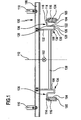
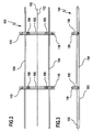
- a skid frame shown in FIGS. 1 to 3, designated as a whole by 100 for receiving an object to be transported, in particular a vehicle body, comprises two parallel to a longitudinal direction 102 aligned, perpendicular to the longitudinal direction 102 spaced apart Skid runners 104, which are designed as essentially rectangular hollow profiles are and on their underside a substantially horizontal contact surface 105 have.
- Each of the skid runners 104 is provided with a support 106 two trusses 108 (see Fig. 2 and 3) connected, which are perpendicular to Extend longitudinal direction 102 over the two skid runners 104 and lengthways the longitudinal direction 102 are spaced apart.
- the cross members 108 each carry two holding devices 110 for releasable Determining the objects to be transported, in particular one to be transported Vehicle body, on the skid frame 100.
- the skid frame 100 is essentially mirror-symmetrical to its longitudinal center plane 112 trained.
- the longitudinal center plane 112 of the ski frame 100 is facing Sides of the elements described as their inside or inside Pages are designated, while those facing away from the longitudinal center plane 112 Pages of these elements as their outside or outside pages be designated.
- each of the supports 106 includes one Fixing area 114, that on the bearing surface 105 of the respective skid runner 104 opposite top 116 of the skid runner 104, preferably by Welding, is fixed.
- An outer area extends from the fixing area 114 of the support 106 Section 118 of support 106 horizontally inward, i.e. towards the Longitudinal center plane 112 of the ski frame 100.
- This horizontal outer section 118 is followed in parallel by one to the longitudinal direction 101 extending bending line 120 a vertically downward extending middle portion 122 of the support 106, which is parallel to the The inside 124 of the skid runner 104 is arranged at a distance from the same.
- the lower end of the middle section 122 is connected along a bending line 126 a horizontally inwardly extending lower portion 128 the support 106.
- the lower section 126 goes into an inner section at a bending line 130 132 of the support 106 above, which extends vertically up to the Traverse 108 extends.
- the inner portion 132 of the support 106 is parallel to the central portion 122 and spaced from the same.
- the upper end of the inner portion 132 is at the associated one Traverse 108, preferably by welding.
- the lower portion of the inner section 132, the lower section 128 and the middle section 122 of the support 106 together form an upward open arcuate section 134 of the support 106.
- the arcuate portion 134 of the support 106 forms together with the outer portion 118 of the support 106 a gooseneck-shaped portion 136 of the support 106.
- the lower ones Areas of the inner portions 132 of the two supports 106 each are fixed to the same crossmember 108 by means of a vertical connected to the longitudinal direction 102 transverse strut 138, which at both ends on a support 106, preferably by Welding, is fixed.
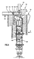
- FIGS. 4 and 5 show the arrangement of the ski frame described above 100 on a conveyor device designed as a roller conveyor 138, which are consecutive along a conveying direction 140, perpendicular to Direction of conveyance 140 aligned and along the conveying direction 140 from each other spaced idlers 142.
- Each of the support rollers 142 comprises a horizontal and perpendicular to the conveying direction 140 aligned shaft 144, which at both ends by means of bearing devices 145 on frame frame supports extending along the conveying direction 140 147, which is, for example, a substantially Z-shaped one Cross section can be rotatably mounted.
- each support body 146 On the inside and / or on the outside of each support body 146, a Wheel flange 149 is provided for lateral guidance of the respective skid runner 104 his.
- the rotational movement of the idler roller 142 is rotatably connected to the Shaft 144 connected pinion (not shown), which over a toothed belt with the output shaft of a drive motor or with a Pinion of another idler roller 142, which in turn from the drive motor or is driven by another support roller 142, in operative connection stands.
- the roller conveyor 138 comprises a cover 150, which in turn is a stationary one Part 152 and a pivotable portion 154 includes.
- the stationary part 152 of the cover 150 comprises a cover plate 155, which extends vertically from a base plate 156 of the roller conveyor 138 at the top in the gap 158 between the inside 124 of the skid runner 104 and the central portion 122 of the support 106 extends into and spaced apart ends from the outer portion 118 of the support 106.
- This cover plate 155 is close to the inside (i.e., close to the median longitudinal plane of the Roller conveyor 138 facing side) of the support body 146 of the support rollers 142nd arranged and has through openings for the passage of the shafts 144 through the cover plate 155.
- the cover plate 155 forms a lower inner cover area 160 of the cover 150th
- the stationary part 152 of the cover 150 further comprises a support plate 162, which extends from the base plate 156 in the horizontal direction extends outside.
- the pivotable portion 154 of the cover 150 includes an outer cover area 166, which (in the working position shown in FIGS. 4 and 5, in which the pivotable part 154 of the cover 150 has the associated one Skid runner 104 covers) vertically from hinge 164 extends up to approximately the height of the center of the skid blade 104.
- an upper cover area 170 which at an angle of, for example, approximately 30 ° inwards against the horizontal and extends across the skid runner 104.
- the top of the top Cover area 170 extends into the space 172 between the Traverse 108 of the ski frame 100 and the outer portion 118 of the support 106 and ends at a distance from the underside of the crossmember 108.
- the lower edge of the upper inner cover area 176 lies below the upper edge of the lower inner cover area 160 so that the upper inner Cover area 176 the lower inner cover area 160 to the inside the roller conveyor 138 covers.
- a passage 180 for the support 106 is formed with vertical boundary walls, which of the middle section 122 of the support 106 is penetrated.
- the components of the cover 150 described above form together a closed channel, which is only accessible through the passage 180 is, the inlet opening 183 points downward, so that dirt particles only in the bottom-up direction in those enclosed by the cover 150 Interior 182 can get. Because the editing and / or Surface treatment of the object held on the skid frame 100 takes place above the cover 150, pass through the processing or surface treatment resulting dirt particles from above to cover 150, so it is very unlikely that such dirt particles get into the area below the passage 180 and then up penetrate through the passage 180 into the interior 182 of the cover 150 can.
- the pivotable Part 154 of the cover 150 - in the absence of the ski frame 100 - from the shown working position about the pivot axis of the hinge 164 are pivoted into a maintenance position (not shown), in which the interior 182 of the cover 150 is accessible from above.
- the upper inner cover area 176 covers the upper area of the skid runner 104 down to the inside of the roller conveyor 138, while the upper covering area 170 the skid blade 104 upwards and the upper area of the skid blade 104 covers to the outside of the roller conveyor 138.
- the outer cover area 166 covers the lower area of the skid runner 104 to the outside of the roller conveyor 138 down, while the lower inner cover area 160 the lower Area of the skid runner 104 covers the inside of the roller conveyor 138.
- a second embodiment of a conveyor device shown in FIGS. 6 and 7 differs from the first embodiment described above in that the conveyor is not a roller conveyor, but is designed as a chain conveyor 184.
- the carrying chain conveyor 184 includes conveyance on both sides of it Longitudinal median plane each have a conveyor chain 186, each one in the Direction of conveyance 140 moving upper run 188 and one in the to Direction of conveyance 140 opposite return direction 190 moving lower Trum 192 has.
- the upper run 188 and the lower run 192 are on their ends (not shown) connected together so that a endless, revolving conveyor chain 186 results.
- the conveyor chain 186 is composed of internal ones which are successive in their longitudinal direction Link plates 194 and outer link plates 196 assembled, which are symmetrical to one another to a longitudinal median plane 198 of the Conveyor chain 186 are opposite.
- Carrier rollers 200 of the chain are each attached to such pairs of link plates of a bearing pin 202 rotatably mounted.
- two support rollers 200 are each one Driver 204 assigned, which as an angle plate with a vertical Section 206 and a horizontal section 208 is formed, the horizontal section 208 together with two arranged on its top, extending in the longitudinal direction of the conveyor chain 186 and perpendicular spaced from the longitudinal direction of the conveyor chain 186, vertical guide plates 210 a receptacle 212 for the skid runner 104 ski frame 100 to be transported by means of the carrying chain conveyor 184 forms.
- the upper run 188 and the lower run 192 of the conveyor chain 186 run by a chain housing 214 which is essentially rectangular in cross section, its inner wall facing the longitudinal center plane of the chain conveyor 184 forms a lower inner cover area 160 for the skid runner 104, which is in the gap 158 between the inside 124 of the skid runner 104 and the central portion 122 of the support 106 and ends below the top 116 of the skid runner 104.
- An outer wall of the chain case 214 forms a stationary lower one outer cover area 216, which extends vertically up to over the Top 116 of the skid runner 104 extends out and at its upper end a strip 218 extending along the conveying direction 140 and made of an elastic one Material, such as rubber, carries.
- a hinge 164 is arranged around the one running along the conveying direction 140 Pivot axis of the pivotable part 154 of the cover 150 of the skid runner 104 is pivotally held on the lower outer cover area 216.
- the pivotable portion 154 of the cover 150 includes an upper outer Covering area 220, which is shown in solid lines in FIG. 6 Working position of the cover 150 vertically from the hinge 164 extends up to the top of ledge 218.
- the upper edge of the upper outer covering region 220 is closed along a bending line 168 to an upper cover area 170, which to the inside of the chain conveyor 184 at an angle of, for example rises about 30 ° against the horizontal and extends into the space 172 between the outer portion 118 of the support 106 and the bottom the cross member 108 of the ski frame 100 extends into it.
- the lower edge of the upper inner cover area 176 lies below the upper edge of the lower inner cover area 160, so that between the lower portion of the upper inner cover portion 176 and the upper portion of the lower inner cover area 160 into the interior 182 of the Cover 150 leading passage 180 with vertical boundary walls is formed, the inlet opening 183 points downward.
- the cover 150 further comprises a support element 122 for the pivotable Part 154 of cover 150, which has a vertical lower portion 224, which is on the inside of the lower outer cover portion 216 is fixed, and includes an upper portion 226 which is substantially below is inclined at the same angle to the horizontal as the upper covering area 170 of the pivotable part 154 of the cover 150.
- a support element 122 for the pivotable Part 154 of cover 150 which has a vertical lower portion 224, which is on the inside of the lower outer cover portion 216 is fixed, and includes an upper portion 226 which is substantially below is inclined at the same angle to the horizontal as the upper covering area 170 of the pivotable part 154 of the cover 150.
- the stationary part 152 of the cover 150 is covered by the lower inner one Cover area 160 and the lower outer cover area 216 and that Support element 122 formed.
- the upper inner covering area covers 176 the upper area of the skid runner 104 to the inside of the carrying chain conveyor 184 down.
- the upper cover area 170 covers the skid runner 104 upwards.
- the upper outer cover area 166 covers the upper area the skid runner 104 to the outside of the support chain conveyor 184.
- the lower outer cover area 216 covers the skid runner 104 to the outside of the Support chain conveyor 184 down.
- the lower inner cover area 160 covers the lower area of the skid runner 104 to the inside of the carrying chain conveyor 184 down.
- the lower region of the upper inner covering region 176 covers the upper area of the lower inner cover area 160 to the inside of the Support chain conveyor 184 down.
- the idler rollers 200 of the conveyor chain 186 roll on rails 228 and 230 for the upper run 188 or for the lower run 192, which are within of the chain housing 214 are arranged and parallel to the conveying direction 140 or extend to the return direction 190.
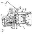
- a third embodiment of a conveyor device shown in FIGS. 8 and 9 differs from the embodiments described above in that the conveyor device as a drag chain conveyor 232 is trained.
- the drag chain conveyor comprises as a conveyor a conveyor chain 186 on each side of its longitudinal median plane with an upper strand 188 which moves along the conveying direction 140, and a lower run 192, which is in a to the conveying direction 140 opposite return direction 190 moves.
- the conveyor chain 186 is made up along the longitudinal direction of the conveyor chain 186 successive link plates 194, 196 together, which are each other in pairs symmetrical to a longitudinal median plane 198 of the conveyor chain 186 are opposite.
- the inner link plates 194 are as angle elements with a horizontal Leg 234 formed, which by means of suitable fasteners are releasably attached to a transport carriage 236.
- the dolly 236 comprises a base body 238 with a cross section in the form of a inverted U, which encompasses the conveyor chain 186.
- each two idlers 200 rotatably mounted.
- the top of the base body 238 forms together with on the top arranged extending in the longitudinal direction of the conveyor chains 186 vertical guide plates 210 a receptacle 212 for a skid runner 104 a ski frame to be transported by means of the drag chain conveyor 232 100th
- the support rollers 200 of the transport carriage 236 roll on two running rails 228 for the upper run 188 or on two tracks 230 for the lower run 192 of the conveyor chain 186 from within a chain housing 214 of the Drag chain conveyor 232 are held.
- An inner wall facing the longitudinal center plane of the drag chain conveyor 232 242 of the chain housing 214 carries a cover plate at its upper end 244, which extends along the conveying direction 140 and an in has essential Z-shaped cross section, with a vertical lower Section 246, a horizontal middle section 248 and a vertical upper section 250, which extends over an angle of, for example about 45 ° to the horizontal inclined portion 254 connects to the outside of the horizontal middle section 248.
- the vertical upper section 250 and the inclined section 252 form together a lower inner cover area 160 for the skid runner 104.
- the upper end of the lower inner cover portion 160 extends at the top in the gap 158 between the inside 124 of the skid runner 104 and the central portion 122 of the support 106.
- Outer wall 254 of chain housing 214 extends up to beyond Support surface 105 of the skid runner 104 and forms a lower outer Covering area 216 for the skid runner 104.
- a hinge 164 On the outside of the lower outer cover area 216 is a hinge 164 arranged with a pivot axis running along the conveying direction 140, by means of which a pivotable part 154 of the cover 150 for the Skid runner 104 from the maintenance position shown in broken lines in FIG. 8 into the working position shown in solid lines in FIG. 8 is pivotable.
- the pivotable portion 154 of the cover 150 includes an upper outer Cover area 220, which extends vertically upwards in the operating position extends approximately to the center of the skid runner 104.
- the upper edge of the upper outer covering region 220 is closed along a bending line 168 to an upper cover area 170, which to the inside of the drag chain conveyor 232 at an angle of, for example rises about 30 ° against the horizontal and extends into the space 172 between the outer portion 118 of the support 106 and the The underside of the crossmember 108 of the ski frame 100 extends into it.
- the lower edge of the upper inner cover area 176 lies below the upper edge of the lower inner cover area 160, so that between the upper inner cover area 176 and lower inner cover area 160 a passage 180 to the interior 182 of the cover 150 is formed which has vertical boundary walls and its inlet opening 183 is directed downwards.
- Cover 150 further includes a support member 222 having a vertical one lower section 224 and an upper section 226 which is below substantially is inclined at the same angle to the horizontal as the upper one Cover area 170 of the pivotable portion 154 of the cover 150, so that in the working position of the cover 150, the upper cover area 170 with its Bottom at the top of the upper portion 226 of the support member 222 rests.
- That of the stationary part 152 and the pivotable part 154 in the operating position enclosed interior 182 contains, in addition to the skid runner 104 also the moving parts of the drag chain conveyor 232, in particular the Conveyor chain 186 with the trolley 236 so that all of these elements are protected from contamination by the cover 150.
- the upper inner covering area covers 176 the upper area of the skid runner 104 to the inside of the drag chain conveyor 232 down.
- the upper cover area 170 covers the skid runner 104 up and the top of the skid blade 104 to the outside of the Drag chain conveyor 232 down.
- the upper outer cover area 220 covers the lower area of skid runner 104 to the outside of the drag chain conveyor 232 down.
- the lower outer cover area 216 covers the lower one Area of the skid runner 104 to the outside of the drag chain conveyor 232 down.
- the lower inner cover area 160 covers the lower area of the Skid runner 104 down to the inside of the drag chain conveyor 232.
- the lower region of the upper inner covering region 176 covers the upper area of the lower inner cover area 160 to the inside of the Drag chain conveyor 232 down.
Landscapes
- Engineering & Computer Science (AREA)
- Mechanical Engineering (AREA)
- Manufacturing & Machinery (AREA)
- Chemical & Material Sciences (AREA)
- Combustion & Propulsion (AREA)
- Transportation (AREA)
- Chain Conveyers (AREA)
- Automobile Manufacture Line, Endless Track Vehicle, Trailer (AREA)
Abstract
Description
- Fig. 1
- einen schematischen Querschnitt durch einen Skidrahmen;
- Fig. 2
- eine schematische Draufsicht von oben auf den Skidrahmen aus Fig. 1;
- Fig. 3
- eine schematische Seitenansicht auf den Skidrahmen aus den Fig. 1 und 2;
- Fig. 4
- einen ausschnittsweisen schematischen Querschnitt durch eine als Rollenbahn ausgebildete Fördervorrichtung mit einem daran angeordneten Skidrahmen;
- Fig. 5
- eine schematische Seitenansicht der Rollenbahn aus Fig. 4, mit der Blickrichtung in Richtung des Pfeiles 5 in Fig. 4;
- Fig. 6
- einen ausschnittsweisen schematischen Querschnitt durch eine als Tragkettenförderer ausgebildete Fördervorrichtung mit einem daran angeordneten Skidrahmen;
- Fig. 7
- eine schematische Seitenansicht des Tragkettenförderers aus Fig. 6, mit der Blickrichtung in Richtung des Pfeiles 7 in Fig. 6;
- Fig. 8
- einen ausschnittsweisen schematischen Querschnitt durch eine als Schleppkettenförderer ausgebildete Fördervorrichtung mit einem daran angeordneten Skidrahmen; und
- Fig. 9
- eine schematische Seitenansicht des Schleppkettenförderers aus Fig. 8, mit der Blickrichtung in Richtung des Pfeiles 9 in Fig. 8.
Claims (28)
- Fördervorrichtung zum Fördern von Werkstücken, insbesondere von Fahrzeugkarosserien, die jeweils auf einem Skidrahmen (100) mit Skidkufen (104) angeordnet sind, längs einer Förderrichtung (140),
dadurch gekennzeichnet, daß die Fördervorrichtung (138, 184, 232) eine Abdeckung (150) für mindestens eine der Skidkufen (104) umfaßt, die einen oberen Abdeckbereich (170) aufweist, welcher im Betriebszustand der Fördervorrichtung (138, 184, 232) mindestens eine der Skidkufen (104) zumindest teilweise nach oben hin abdeckt. - Fördervorrichtung nach Anspruch 1, dadurch gekennzeichnet, daß der obere Abdeckbereich (170) mindestens eine der Skidkufen (104) vollständig nach oben hin abdeckt.
- Fördervorrichtung nach einem der Ansprüche 1 oder 2, dadurch gekennzeichnet, daß der obere Abdeckbereich (170) im Betriebszustand der Fördervorrichtung (138, 184, 232) gegenüber der Horizontalen, vorzugsweise um einen Winkel von ungefähr 20° bis ungefähr 40°, geneigt ist.
- Fördervorrichtung nach einem der Ansprüche 1 bis 3, dadurch gekennzeichnet, daß sich der obere Abdeckbereich (170) in einen Zwischenraum (172) zwischen der Skidkufe (104) und einer Traverse (108) des Skidrahmens (100) hineinerstreckt.
- Fördervorrichtung nach einem der Ansprüche 1 bis 4, dadurch gekennzeichnet, daß die Abdeckung (150) einen äußeren Abdeckbereich (166; 216, 220) aufweist, welcher mindestens eine der Skidkufen (104) zumindest teilweise zur Außenseite der Fördervorrichtung (138, 184, 232) hin abdeckt.
- Fördervorrichtung nach Anspruch 5, dadurch gekennzeichnet, daß der äußere Abdeckbereich (166; 216, 220) mindestens eine der Skidkufen (104) zur Außenseite der Fördervorrichtung (138, 184, 232) hin vollständig abdeckt.
- Fördervorrichtung nach einem der Ansprüche 5 oder 6, dadurch gekennzeichnet, daß der äußere Abdeckbereich (166; 216, 220) im Betriebszustand der Fördervorrichtung (138, 184, 232) im wesentlichen vertikal ausgerichtet ist.
- Fördervorrichtung nach einem der Ansprüche 1 bis 7, dadurch gekennzeichnet, daß die Abdeckung (150) einen inneren Abdeckbereich (160, 176) aufweist, welcher mindestens eine der Skidkufen (104) zumindest teilweise zur Innenseite der Fördervorrichtung (138, 184, 232) hin abdeckt.
- Fördervorrichtung nach Anspruch 8, dadurch gekennzeichnet, daß die Abdeckung (150) einen oberen inneren Abdeckbereich (176), welcher mit dem oberen Abdeckbereich (170) verbunden ist, und einen unteren inneren Abdeckbereich (160), welcher von dem oberen inneren Abdeckbereich (176) und dem oberen Abdeckbereich (170) getrennt ist, aufweist.
- Fördervorrichtung nach Anspruch 9, dadurch gekennzeichnet, daß einer der inneren Abdeckbereiche (160, 176) den jeweils anderen der inneren Abdeckbereiche (160, 176) zur Innenseite der Fördervorrichtung (138, 184, 232) hin zumindest teilweise abdeckt.
- Fördervorrichtung nach einem der Ansprüche 9 oder 10, dadurch gekennzeichnet, daß der obere innere Abdeckbereich (176) den unteren inneren Abdeckbereich (160) zur Innenseite der Fördervorrichtung (138, 184, 232) hin zumindest teilweise abdeckt.
- Fördervorrichtung nach einem der Ansprüche 9 bis 11, dadurch gekennzeichnet, daß der obere Abdeckbereich (170) den unteren inneren Abdeckbereich (160) zumindest teilweise nach oben hin abdeckt.
- Fördervorrichtung nach einem der Ansprüche 9 bis 12, dadurch gekennzeichnet, daß mindestens einer der inneren Abdeckbereiche (160, 176) im Betriebszustand der Fördervorrichtung (138, 184, 232) im wesentlichen vertikal ausgerichtet ist.
- Fördervorrichtung nach Anspruch 13, dadurch gekennzeichnet, daß beide inneren Abdeckbereiche (160, 176) im Betriebszustand der Fördervorrichtung (138, 184, 232) im wesentlichen vertikal ausgerichtet sind.
- Fördervorrichtung nach einem der Ansprüche 1 bis 14, dadurch gekennzeichnet, daß die Abdeckung (150) einen Durchlaß (180) für den Durchtritt mindestens einer Stütze (106) mindestens einer Skidkufe (104) des Skidrahmens (100) aufweist.
- Fördervorrichtung nach Anspruch 15, dadurch gekennzeichnet, daß der Durchlaß (180) eine nach unten, vorzugsweise im wesentlichen vertikal nach unten, weisende Einlaßöffnung (183) aufweist.
- Fördervorrichtung nach einem der Ansprüche 1 bis 16, dadurch gekennzeichnet, daß zumindest der obere Abdeckbereich (170) der Abdeckung (150) aus einer Arbeitsstellung, in welcher der obere Abdeckbereich (170) mindestens eine der Skidkufen (104) nach oben hin zumindest teilweise abdeckt, in eine Wartungsstellung bewegbar ist, in welcher der Förderweg der mindestens einen Skidkufe (104) zugänglich ist.
- Fördervorrichtung nach Anspruch 17, dadurch gekennzeichnet, daß der obere Abdeckbereich (170) aus der Arbeitsstellung in die Wartungsstellung schwenkbar ist.
- Fördervorrichtung nach Anspruch 18, dadurch gekennzeichnet, daß der obere Abdeckbereich (170) um eine im wesentlichen parallel zu der Förderrichtung (140) gerichtete Schwenkachse aus der Arbeitssteliung in die Wartungsstellung schwenkbar ist.
- Fördervorrichtung nach einem der Ansprüche 1 bis 19, dadurch gekennzeichnet, daß die Fördervorrichtung als eine Rollenbahn (138), als ein Tragkettenförderer (184) oder als ein Schleppkettenförderer (232) ausgebildet ist.
- Skidrahmen zum Fördern von Werkstücken, insbesondere Fahrzeugkarosserien, umfassend mindestens zwei Skidkufen (104), die quer zur Förderrichtung (140) voneinander beabstandet sind, und mindestens eine Traverse (108), die über jeweils eine Stütze (106) mit den Skidkufen (104) verbunden ist, wobei die Stütze (106) an einem Festlegebereich (114) an der jeweiligen Skidkufe (104) festgelegt ist, dadurch gekennzeichnet, daß die Stütze (106) einen nach oben offenen bogenförmigen Abschnitt (134) umfaßt.
- Skidrahmen nach Anspruch 21, dadurch gekennzeichnet, daß die Stütze (106) einen schwanenhalsförmigen Abschnitt (136) umfaßt.
- Skidrahmen nach einem der Ansprüche 21 oder 22, dadurch gekennzeichnet, daß die Stütze (106) mindestens einen Abschnitt (122, 128) umfaßt, der unterhalb des Festlegebereichs (114) der Stütze (106) angeordnet ist.
- Skidrahmen nach einem der Ansprüche 21 bis 23, dadurch gekennzeichnet, daß die Stütze (106) an einer Oberseite (116) der jeweiligen Skidkufe (106) festgelegt ist.
- Skidrahmen nach einem der Ansprüche 21 bis 24, dadurch gekennzeichnet, daß die Stütze (106) einen sich von dem Festlegebereich (114) aus quer zur Vertikalen, vorzugsweise im wesentlichen horizontal, erstreckenden äußeren Abschnitt (118) umfaßt.
- Skidrahmen nach einem der Ansprüche 21 bis 25, dadurch gekennzeichnet, daß die Stütze (106) einen sich von der Traverse (108) aus quer zur Horizontalen, vorzugsweise im wesentlichen vertikal, erstreckenden inneren Abschnitt (132) umfaßt.
- Skidrahmen nach Anspruch 26, dadurch gekennzeichnet, daß die Stütze (106) einen zwischen dem Festlegebereich (114) und dem inneren Abschnitt (132) angeordneten, sich quer zur Horizontalen, im wesentlichen vertikal, erstreckenden mittleren Abschnitt (122) umfaßt.
- Skidrahmen nach einem der Ansprüche 21 bis 27, dadurch gekennzeichnet, daß die Stütze (106) einen zwischen dem Festlegebereich (114) und dem inneren Abschnitt (132) angeordneten, sich quer zur Vertikalen, vorzugsweise im wesentlichen horizontal, erstreckenden und unterhalb des Festlegebereichs (114) angeordneten unteren Abschnitt (128) umfaßt.
Applications Claiming Priority (2)
| Application Number | Priority Date | Filing Date | Title |
|---|---|---|---|
| DE2002103845 DE10203845A1 (de) | 2002-01-31 | 2002-01-31 | Fördervorrichtung und Skidrahmen zum Fördern von Werkstücken |
| DE10203845 | 2002-01-31 |
Publications (2)
| Publication Number | Publication Date |
|---|---|
| EP1332955A2 true EP1332955A2 (de) | 2003-08-06 |
| EP1332955A3 EP1332955A3 (de) | 2004-11-17 |
Family
ID=7713475
Family Applications (1)
| Application Number | Title | Priority Date | Filing Date |
|---|---|---|---|
| EP03002007A Withdrawn EP1332955A3 (de) | 2002-01-31 | 2003-01-28 | Fördervorrichtung und Skidrahmen zum Fördern von Werkstücken |
Country Status (2)
| Country | Link |
|---|---|
| EP (1) | EP1332955A3 (de) |
| DE (1) | DE10203845A1 (de) |
Cited By (3)
| Publication number | Priority date | Publication date | Assignee | Title |
|---|---|---|---|---|
| CN105253534A (zh) * | 2015-10-13 | 2016-01-20 | 中汽昌兴(洛阳)机电设备工程有限公司 | 重型链式输送机及其输送链条 |
| EP2325591B1 (de) | 2009-11-24 | 2018-01-10 | Eisenmann SE | Anlage zum Trocknen von Gegenständen |
| CN114453168A (zh) * | 2022-02-10 | 2022-05-10 | 江苏长虹智能装备股份有限公司 | 一种适用多种大中客车型活动式支点型滑橇 |
Family Cites Families (5)
| Publication number | Priority date | Publication date | Assignee | Title |
|---|---|---|---|---|
| JPS5791714U (de) * | 1980-11-28 | 1982-06-05 | ||
| GB2162137B (en) * | 1984-06-18 | 1988-07-20 | Daifuku Kk | Conveying system |
| WO1989000524A1 (fr) * | 1987-07-09 | 1989-01-26 | Sietam Systemes | Systeme de manutention a luges |
| DE29907776U1 (de) * | 1999-05-03 | 1999-09-02 | Bleichert Förderanlagen GmbH, 74706 Osterburken | Schienenförderanlage für auf Stützrollen gelagerte Förderwagen |
| DE19926623A1 (de) * | 1999-06-11 | 2000-12-21 | Duerr Systems Gmbh | Fördervorrichtung zum Fördern von Werkstücken, insbesondere Fahrzeugkarosserien |
-
2002
- 2002-01-31 DE DE2002103845 patent/DE10203845A1/de not_active Withdrawn
-
2003
- 2003-01-28 EP EP03002007A patent/EP1332955A3/de not_active Withdrawn
Cited By (4)
| Publication number | Priority date | Publication date | Assignee | Title |
|---|---|---|---|---|
| EP2325591B1 (de) | 2009-11-24 | 2018-01-10 | Eisenmann SE | Anlage zum Trocknen von Gegenständen |
| CN105253534A (zh) * | 2015-10-13 | 2016-01-20 | 中汽昌兴(洛阳)机电设备工程有限公司 | 重型链式输送机及其输送链条 |
| CN114453168A (zh) * | 2022-02-10 | 2022-05-10 | 江苏长虹智能装备股份有限公司 | 一种适用多种大中客车型活动式支点型滑橇 |
| CN114453168B (zh) * | 2022-02-10 | 2022-12-13 | 江苏长虹智能装备股份有限公司 | 一种适用多种大中客车型活动式支点型滑橇 |
Also Published As
| Publication number | Publication date |
|---|---|
| EP1332955A3 (de) | 2004-11-17 |
| DE10203845A1 (de) | 2003-08-14 |
Similar Documents
| Publication | Publication Date | Title |
|---|---|---|
| EP0641984B1 (de) | Beschichtungsanlage | |
| EP1383696B1 (de) | Fördervorrichtung zum fördern von werkstücken durch einen behandlungsbereich zur oberflächenbehandlung der werkstücke | |
| DE19926625A1 (de) | Verfahren und Fördervorrichtung zum Fördern von Fahrzeugkarosserien durch ein Behandlungsbad | |
| DE602004000974T2 (de) | Muldenbandförderer | |
| DE102011103729A1 (de) | Vorrichtung zum Fördern von Gegenständen | |
| DE112018003784T5 (de) | Hydraulische schaufel | |
| EP0434862B1 (de) | Aushebevorrichtung, insbesondere für Förderbahnen | |
| DE10210942B4 (de) | Anlage zum Behandeln, insbesondere zum kataphoretischen Tauchlackieren, von Gegenständen, insbesondere von Fahrzeugkarosserien | |
| EP0541850A1 (de) | Kurvengängiges Plattenband | |
| EP0255620B2 (de) | Rollenbahn für Fahrzeugkarosserie-Transportschlitten | |
| DE102011118791B4 (de) | Förderband zur Verwendung in einer Fräsvorrichtung und Fräsvorrichtung mit einem solchen Förderband | |
| EP2986404B9 (de) | Transportvorrichtung sowie deren verwendung | |
| DE3913019A1 (de) | Spaenefoerderer | |
| DE2006210A1 (de) | Transportvorrichtung | |
| EP0436081A1 (de) | Fördereinrichtung | |
| DE10203845A1 (de) | Fördervorrichtung und Skidrahmen zum Fördern von Werkstücken | |
| EP0678463B1 (de) | Kettenförderer | |
| DE19926624A1 (de) | Skidrahmen zum Fördern von Werkstücken, insbesondere von Fahrzeugkarosserien, und Drehvorrichtung zum Drehen eines solchen Skidrahmens | |
| DE2743602A1 (de) | Vorrichtung zur entnahme von silage aus einem silo | |
| DE9312243U1 (de) | Fördereinrichtung | |
| DE20201448U1 (de) | Fördervorrichtung und Skidrahmen zum Fördern von Werkstücken | |
| DE19950202A1 (de) | Rollenbahn für Skidrahmen | |
| DE3711697A1 (de) | Rollenbahn fuer fahrzeugkarosserie-transportschlitten | |
| AT390087B (de) | Vorrichtung zur raeumung, insbesondere saeuberung, von verkehrsflaechen | |
| AT414202B (de) | Reinigungseinrichtung insbesondere für backbleche |
Legal Events
| Date | Code | Title | Description |
|---|---|---|---|
| PUAI | Public reference made under article 153(3) epc to a published international application that has entered the european phase |
Free format text: ORIGINAL CODE: 0009012 |
|
| AK | Designated contracting states |
Designated state(s): AT BE BG CH CY CZ DE DK EE ES FI FR GB GR HU IE IT LI LU MC NL PT SE SI SK TR |
|
| AX | Request for extension of the european patent |
Extension state: AL LT LV MK RO |
|
| PUAL | Search report despatched |
Free format text: ORIGINAL CODE: 0009013 |
|
| AK | Designated contracting states |
Kind code of ref document: A3 Designated state(s): AT BE BG CH CY CZ DE DK EE ES FI FR GB GR HU IE IT LI LU MC NL PT SE SI SK TR |
|
| AX | Request for extension of the european patent |
Extension state: AL LT LV MK RO |
|
| AKX | Designation fees paid | ||
| REG | Reference to a national code |
Ref country code: DE Ref legal event code: 8566 |
|
| STAA | Information on the status of an ep patent application or granted ep patent |
Free format text: STATUS: THE APPLICATION IS DEEMED TO BE WITHDRAWN |
|
| 18D | Application deemed to be withdrawn |
Effective date: 20050518 |