EP1332720B1 - Concentration measuring instrument - Google Patents
Concentration measuring instrument Download PDFInfo
- Publication number
- EP1332720B1 EP1332720B1 EP01970294A EP01970294A EP1332720B1 EP 1332720 B1 EP1332720 B1 EP 1332720B1 EP 01970294 A EP01970294 A EP 01970294A EP 01970294 A EP01970294 A EP 01970294A EP 1332720 B1 EP1332720 B1 EP 1332720B1
- Authority
- EP
- European Patent Office
- Prior art keywords
- light
- liquid crystal
- concentration
- light source
- measuring apparatus
- Prior art date
- Legal status (The legal status is an assumption and is not a legal conclusion. Google has not performed a legal analysis and makes no representation as to the accuracy of the status listed.)
- Expired - Lifetime
Links
- 239000004973 liquid crystal related substance Substances 0.000 claims abstract description 94
- 239000013543 active substance Substances 0.000 claims abstract description 19
- 239000008280 blood Substances 0.000 claims description 55
- 210000004369 blood Anatomy 0.000 claims description 55
- 239000004988 Nematic liquid crystal Substances 0.000 claims description 36
- 238000001514 detection method Methods 0.000 claims description 34
- 230000000694 effects Effects 0.000 claims description 18
- NOESYZHRGYRDHS-UHFFFAOYSA-N insulin Chemical compound N1C(=O)C(NC(=O)C(CCC(N)=O)NC(=O)C(CCC(O)=O)NC(=O)C(C(C)C)NC(=O)C(NC(=O)CN)C(C)CC)CSSCC(C(NC(CO)C(=O)NC(CC(C)C)C(=O)NC(CC=2C=CC(O)=CC=2)C(=O)NC(CCC(N)=O)C(=O)NC(CC(C)C)C(=O)NC(CCC(O)=O)C(=O)NC(CC(N)=O)C(=O)NC(CC=2C=CC(O)=CC=2)C(=O)NC(CSSCC(NC(=O)C(C(C)C)NC(=O)C(CC(C)C)NC(=O)C(CC=2C=CC(O)=CC=2)NC(=O)C(CC(C)C)NC(=O)C(C)NC(=O)C(CCC(O)=O)NC(=O)C(C(C)C)NC(=O)C(CC(C)C)NC(=O)C(CC=2NC=NC=2)NC(=O)C(CO)NC(=O)CNC2=O)C(=O)NCC(=O)NC(CCC(O)=O)C(=O)NC(CCCNC(N)=N)C(=O)NCC(=O)NC(CC=3C=CC=CC=3)C(=O)NC(CC=3C=CC=CC=3)C(=O)NC(CC=3C=CC(O)=CC=3)C(=O)NC(C(C)O)C(=O)N3C(CCC3)C(=O)NC(CCCCN)C(=O)NC(C)C(O)=O)C(=O)NC(CC(N)=O)C(O)=O)=O)NC(=O)C(C(C)CC)NC(=O)C(CO)NC(=O)C(C(C)O)NC(=O)C1CSSCC2NC(=O)C(CC(C)C)NC(=O)C(NC(=O)C(CCC(N)=O)NC(=O)C(CC(N)=O)NC(=O)C(NC(=O)C(N)CC=1C=CC=CC=1)C(C)C)CC1=CN=CN1 NOESYZHRGYRDHS-UHFFFAOYSA-N 0.000 claims description 16
- 102000004877 Insulin Human genes 0.000 claims description 8
- 108090001061 Insulin Proteins 0.000 claims description 8
- 229940125396 insulin Drugs 0.000 claims description 8
- 238000012544 monitoring process Methods 0.000 claims description 6
- 238000012360 testing method Methods 0.000 abstract description 4
- 230000003287 optical effect Effects 0.000 description 106
- 239000000523 sample Substances 0.000 description 63
- 230000010287 polarization Effects 0.000 description 52
- 238000005259 measurement Methods 0.000 description 42
- 238000000034 method Methods 0.000 description 35
- 239000000243 solution Substances 0.000 description 29
- 238000010586 diagram Methods 0.000 description 23
- 230000001965 increasing effect Effects 0.000 description 15
- WQZGKKKJIJFFOK-GASJEMHNSA-N Glucose Natural products OC[C@H]1OC(O)[C@H](O)[C@@H](O)[C@@H]1O WQZGKKKJIJFFOK-GASJEMHNSA-N 0.000 description 12
- 230000006870 function Effects 0.000 description 12
- 239000000758 substrate Substances 0.000 description 10
- 230000007423 decrease Effects 0.000 description 9
- 210000000624 ear auricle Anatomy 0.000 description 9
- XLYOFNOQVPJJNP-UHFFFAOYSA-N water Substances O XLYOFNOQVPJJNP-UHFFFAOYSA-N 0.000 description 9
- 239000012491 analyte Substances 0.000 description 7
- 239000008103 glucose Substances 0.000 description 6
- 238000002347 injection Methods 0.000 description 6
- 239000007924 injection Substances 0.000 description 6
- 230000008901 benefit Effects 0.000 description 5
- 210000002700 urine Anatomy 0.000 description 5
- 238000004891 communication Methods 0.000 description 4
- 238000010276 construction Methods 0.000 description 4
- 230000036541 health Effects 0.000 description 4
- 230000001360 synchronised effect Effects 0.000 description 4
- 238000002834 transmittance Methods 0.000 description 4
- 238000004458 analytical method Methods 0.000 description 3
- 238000001914 filtration Methods 0.000 description 3
- 238000009499 grossing Methods 0.000 description 3
- 238000013208 measuring procedure Methods 0.000 description 3
- 230000008569 process Effects 0.000 description 3
- 238000012545 processing Methods 0.000 description 3
- 210000004243 sweat Anatomy 0.000 description 3
- 238000010408 sweeping Methods 0.000 description 3
- 208000024891 symptom Diseases 0.000 description 3
- 238000012935 Averaging Methods 0.000 description 2
- VYPSYNLAJGMNEJ-UHFFFAOYSA-N Silicium dioxide Chemical compound O=[Si]=O VYPSYNLAJGMNEJ-UHFFFAOYSA-N 0.000 description 2
- 230000005856 abnormality Effects 0.000 description 2
- 230000005540 biological transmission Effects 0.000 description 2
- 230000008859 change Effects 0.000 description 2
- 239000000470 constituent Substances 0.000 description 2
- 210000004087 cornea Anatomy 0.000 description 2
- 239000013078 crystal Substances 0.000 description 2
- 238000007405 data analysis Methods 0.000 description 2
- 230000003247 decreasing effect Effects 0.000 description 2
- 238000013461 design Methods 0.000 description 2
- 238000003745 diagnosis Methods 0.000 description 2
- 238000010438 heat treatment Methods 0.000 description 2
- 230000001939 inductive effect Effects 0.000 description 2
- 208000015181 infectious disease Diseases 0.000 description 2
- 230000007246 mechanism Effects 0.000 description 2
- 230000002441 reversible effect Effects 0.000 description 2
- 230000035945 sensitivity Effects 0.000 description 2
- WUPHOULIZUERAE-UHFFFAOYSA-N 3-(oxolan-2-yl)propanoic acid Chemical compound OC(=O)CCC1CCCO1 WUPHOULIZUERAE-UHFFFAOYSA-N 0.000 description 1
- 229920000742 Cotton Polymers 0.000 description 1
- 102000004190 Enzymes Human genes 0.000 description 1
- 108090000790 Enzymes Proteins 0.000 description 1
- 206010020751 Hypersensitivity Diseases 0.000 description 1
- XUIMIQQOPSSXEZ-UHFFFAOYSA-N Silicon Chemical compound [Si] XUIMIQQOPSSXEZ-UHFFFAOYSA-N 0.000 description 1
- RTAQQCXQSZGOHL-UHFFFAOYSA-N Titanium Chemical compound [Ti] RTAQQCXQSZGOHL-UHFFFAOYSA-N 0.000 description 1
- 208000003443 Unconsciousness Diseases 0.000 description 1
- 210000001015 abdomen Anatomy 0.000 description 1
- 238000010521 absorption reaction Methods 0.000 description 1
- 208000030961 allergic reaction Diseases 0.000 description 1
- 230000004075 alteration Effects 0.000 description 1
- 230000002421 anti-septic effect Effects 0.000 description 1
- 238000000149 argon plasma sintering Methods 0.000 description 1
- WQZGKKKJIJFFOK-VFUOTHLCSA-N beta-D-glucose Chemical compound OC[C@H]1O[C@@H](O)[C@H](O)[C@@H](O)[C@@H]1O WQZGKKKJIJFFOK-VFUOTHLCSA-N 0.000 description 1
- 230000002457 bidirectional effect Effects 0.000 description 1
- 230000017531 blood circulation Effects 0.000 description 1
- 210000001124 body fluid Anatomy 0.000 description 1
- 239000010839 body fluid Substances 0.000 description 1
- 229910052980 cadmium sulfide Inorganic materials 0.000 description 1
- 238000004364 calculation method Methods 0.000 description 1
- 230000015556 catabolic process Effects 0.000 description 1
- 230000001413 cellular effect Effects 0.000 description 1
- 230000002354 daily effect Effects 0.000 description 1
- 238000006731 degradation reaction Methods 0.000 description 1
- 230000001419 dependent effect Effects 0.000 description 1
- 206010012601 diabetes mellitus Diseases 0.000 description 1
- 238000010790 dilution Methods 0.000 description 1
- 239000012895 dilution Substances 0.000 description 1
- 229940079593 drug Drugs 0.000 description 1
- 239000003814 drug Substances 0.000 description 1
- 239000000428 dust Substances 0.000 description 1
- 238000005516 engineering process Methods 0.000 description 1
- 230000003203 everyday effect Effects 0.000 description 1
- 230000001747 exhibiting effect Effects 0.000 description 1
- 239000000284 extract Substances 0.000 description 1
- 238000000605 extraction Methods 0.000 description 1
- 238000001727 in vivo Methods 0.000 description 1
- 239000006193 liquid solution Substances 0.000 description 1
- 238000013507 mapping Methods 0.000 description 1
- 239000000463 material Substances 0.000 description 1
- 238000000691 measurement method Methods 0.000 description 1
- 230000015654 memory Effects 0.000 description 1
- 229910052751 metal Inorganic materials 0.000 description 1
- 239000002184 metal Substances 0.000 description 1
- 238000012986 modification Methods 0.000 description 1
- 230000004048 modification Effects 0.000 description 1
- 230000010355 oscillation Effects 0.000 description 1
- 239000002245 particle Substances 0.000 description 1
- 238000000711 polarimetry Methods 0.000 description 1
- 230000001902 propagating effect Effects 0.000 description 1
- 230000010349 pulsation Effects 0.000 description 1
- 210000001747 pupil Anatomy 0.000 description 1
- 238000012887 quadratic function Methods 0.000 description 1
- 229910052594 sapphire Inorganic materials 0.000 description 1
- 239000010980 sapphire Substances 0.000 description 1
- 239000004065 semiconductor Substances 0.000 description 1
- 238000011896 sensitive detection Methods 0.000 description 1
- 229910052710 silicon Inorganic materials 0.000 description 1
- 239000010703 silicon Substances 0.000 description 1
- 239000000377 silicon dioxide Substances 0.000 description 1
- 230000035900 sweating Effects 0.000 description 1
- 238000002560 therapeutic procedure Methods 0.000 description 1
- 239000010936 titanium Substances 0.000 description 1
- 229910052719 titanium Inorganic materials 0.000 description 1
- 230000002463 transducing effect Effects 0.000 description 1
- 238000011144 upstream manufacturing Methods 0.000 description 1
- 238000005353 urine analysis Methods 0.000 description 1
- 230000000007 visual effect Effects 0.000 description 1
Images


Classifications
-
- A—HUMAN NECESSITIES
- A61—MEDICAL OR VETERINARY SCIENCE; HYGIENE
- A61B—DIAGNOSIS; SURGERY; IDENTIFICATION
- A61B5/00—Measuring for diagnostic purposes; Identification of persons
- A61B5/145—Measuring characteristics of blood in vivo, e.g. gas concentration or pH-value ; Measuring characteristics of body fluids or tissues, e.g. interstitial fluid or cerebral tissue
- A61B5/1455—Measuring characteristics of blood in vivo, e.g. gas concentration or pH-value ; Measuring characteristics of body fluids or tissues, e.g. interstitial fluid or cerebral tissue using optical sensors, e.g. spectral photometrical oximeters
- A61B5/14558—Measuring characteristics of blood in vivo, e.g. gas concentration or pH-value ; Measuring characteristics of body fluids or tissues, e.g. interstitial fluid or cerebral tissue using optical sensors, e.g. spectral photometrical oximeters by polarisation
-
- A—HUMAN NECESSITIES
- A61—MEDICAL OR VETERINARY SCIENCE; HYGIENE
- A61B—DIAGNOSIS; SURGERY; IDENTIFICATION
- A61B5/00—Measuring for diagnostic purposes; Identification of persons
- A61B5/0059—Measuring for diagnostic purposes; Identification of persons using light, e.g. diagnosis by transillumination, diascopy, fluorescence
- A61B5/0082—Measuring for diagnostic purposes; Identification of persons using light, e.g. diagnosis by transillumination, diascopy, fluorescence adapted for particular medical purposes
- A61B5/0088—Measuring for diagnostic purposes; Identification of persons using light, e.g. diagnosis by transillumination, diascopy, fluorescence adapted for particular medical purposes for oral or dental tissue
-
- A—HUMAN NECESSITIES
- A61—MEDICAL OR VETERINARY SCIENCE; HYGIENE
- A61B—DIAGNOSIS; SURGERY; IDENTIFICATION
- A61B5/00—Measuring for diagnostic purposes; Identification of persons
- A61B5/41—Detecting, measuring or recording for evaluating the immune or lymphatic systems
- A61B5/411—Detecting or monitoring allergy or intolerance reactions to an allergenic agent or substance
-
- G—PHYSICS
- G01—MEASURING; TESTING
- G01J—MEASUREMENT OF INTENSITY, VELOCITY, SPECTRAL CONTENT, POLARISATION, PHASE OR PULSE CHARACTERISTICS OF INFRARED, VISIBLE OR ULTRAVIOLET LIGHT; COLORIMETRY; RADIATION PYROMETRY
- G01J4/00—Measuring polarisation of light
- G01J4/04—Polarimeters using electric detection means
-
- G—PHYSICS
- G01—MEASURING; TESTING
- G01N—INVESTIGATING OR ANALYSING MATERIALS BY DETERMINING THEIR CHEMICAL OR PHYSICAL PROPERTIES
- G01N21/00—Investigating or analysing materials by the use of optical means, i.e. using sub-millimetre waves, infrared, visible or ultraviolet light
- G01N21/17—Systems in which incident light is modified in accordance with the properties of the material investigated
- G01N21/21—Polarisation-affecting properties
- G01N21/211—Ellipsometry
-
- A—HUMAN NECESSITIES
- A61—MEDICAL OR VETERINARY SCIENCE; HYGIENE
- A61B—DIAGNOSIS; SURGERY; IDENTIFICATION
- A61B5/00—Measuring for diagnostic purposes; Identification of persons
- A61B5/0002—Remote monitoring of patients using telemetry, e.g. transmission of vital signals via a communication network
- A61B5/0031—Implanted circuitry
Definitions
- the present invention relates to a technology for measuring the concentration of an optically active substance dissolved in a solution, without using any mechanical moving devices and relying only on a purely electronic control method using an electronically-controllable, optical rotation control element.
- the invention achieves a system for safe measurement of blood sugar concentration, management of the measured concentration, and notification of an alarm condition, wherein the system measures the concentration of blood sugar in a stable and non-harming way over an extended period of time, ideally by noninvasively measuring the blood sugar concentration in a human body or optically measuring the blood sugar concentration in urine in a non-contacting manner, or by using a linearly polarized light emitting element and a compact liquid-crystal, low-voltage, low-power consumption type optical rotation angle detecting element, both implanted in a human body.
- the invention provides a support tool to assist their social activities by achieving a system for issuing an alarm in an audible or visual manner or for automatically administering insulin or glucose as an emergency and temporary treatment when it could be expected that a serious effect to the human body would otherwise result. If a noninvasive blood sugar monitor is achieved, social activities free from blood taking can be ensured, especially for potential diabetics who account for nearly 10% of the population, and a useful health care apparatus can thus be provided.
- EP 0 805 352 A1 discloses a polarimeter in particular for use in a method of urine analysis in which the concentration of an optically active substance in urine is determined by measuring an angle of rotation of said urine.
- the polarimeter comprises a monochromatic light source for projecting light, a polarizer for transmitting only a polarized component of the projected light, a sample cell for holding a specimen and arranged in such a manner that the light transmitted through said polarizer is transmitted through said specimen, magnetic field application means for applying a magnetic field to said specimen, magnetic field sweeping means for sweeping said magnetic field, an analyser for transmitting only a polarized component of the light transmitted through said specimen, a light sensor for detecting the light transmitted through said analyser, and calculation means for calculating an angle of rotation of said specimen based on a magnetic sweep signal of said magnetic field sweeping means and an output signal of said light sensor.
- US 5,787,890 discloses an eye examination apparatus for analysing an eye having an interior portion and a posterior portion, said apparatus comprising a polarized light source for producing an incident diagnostic beam of known state of polarization, an optical system transmitting said incident diagnostic beam into an eye through the pupil, collecting a reflective return diagnostic beam, and directing it to a polarization sensitive detection device for collecting and transducing information about the state of polarization of said return diagnostic beam into a representative electrical signal, and a cornea polarization compensator to modify the polarization of the incident and/or return diagnostic beam to facilitate assessment of any alteration of the polarization state of said return diagnostic beam caused by the polarization properties of the posterior portion of the eye.
- the detection device may in particular be an ellipsometer, and the cornea polarization compensator may comprise besides others a variable retarder, preferably a liquid crystal retarder, for changing the polarization of the incident beam from circular to elliptical, and to restore circular polarization of the return beam.
- a variable retarder preferably a liquid crystal retarder
- US 5,009,230 discloses a device for the non-invasive determination of the concentration of blood glucose in a patient, the device comprising an infrared light source, means for repetitively producing two alternating linearly-polarized orthogonal states of said infrared light, means for directing said two states of infrared light non-invasively through a selective tissue of said patient, polarizing means for receiving said two states subsequent to passage through said tissue of said patient and for passage of portions of said two states in a direction of transmission of said polarizing means, detector means for detecting the intensities of said portions of said two states passing through said polarizing means, the intensities being related to glucose concentration and absorption in said tissue, means for producing a sum and a difference of said states received by said detector means, and means for providing a ratio of said sum and said difference of said intensities to provide a signal related only to said glucose concentration.
- the invention achieves this problem by providing a concentration measuring apparatus having the features of claim 1.
- Advantageous embodiments thereof are mentioned in the dependent claims the wording of which is herewith incorporated by reference to avoid unnecessary text repetition.
- the invention is capable of providing a noninvasive blood sugar monitoring apparatus that measures sugar concentration in human blood without taking a blood sample. To achieve this, sugar concentration must be computed by measuring the light transmittance in a human body without using any moving parts.
- an automatic drug administering device can be used in combination with the automatic blood sugar measuring apparatus so that a safe amount of sugar or insulin can be automatically administered as a relief measure to prevent the patient from becoming unconscious.
- the above apparatus facilitates the social activities of diabetics and potential diabetics. Even if the noninvasive blood sugar measurement thus taken contains a certain degree of error, providing warning to the patient before an accident occurs due to the blood sugar dropping below the normal level offers an advantage if it does not cause real harm.
- social activity support applications unlike the case of a precision blood sugar measuring apparatus for diagnosis or scientific analysis, a simple and easy-to-use blood sugar predictive measurement system that tolerates a finite degree of error is strongly needed. There is thus a need in society to provide a portable and handy noninvasive blood sugar concentration estimating apparatus.
- the point of the configuration of the present invention is the electro-optical modulation of optical rotation by a twisted nematic liquid crystal element.
- sugar concentration can be measured by combining this liquid crystal element with a linear polarizer and a light receiving element. If an electro-optical phase modulating element constructed from a parallel aligned liquid crystal element is added to the above combination, and the amount of light is measured by converting elliptically polarized light into linearly polarized light, the accuracy of the optical rotation measurement further increases.
- linearly polarized light is irradiated into an optically active sample
- elliptically polarized light emerging from the sample is compensated for by the electro-optical optical rotation modulating element constructed from a twisted nematic liquid crystal element
- the elliptically polarized light is converted back into the linearly polarized light by the electro-optical phase modulating element
- an extreme value of detected light intensity is read
- the drive voltages of the twisted nematic liquid crystal element and the phase modulating parallel aligned liquid crystal element are feedback-controlled
- the concentration of an optically active substance in the solution is computed by estimation from the electrical control voltage.
- the measurement of the transmitted light intensity and the measurement of the optical rotation are performed in parallel or in sequence within a short time, and the concentration of blood sugar, for example, is estimated from the predefined relationship between the value of the optical rotation and the light intensity within the sugar concentration measuring wavelength range.
- S/N signal-to-noise ratio
- a laser diode capable of emitting linearly polarized light or a combination of a light-emitting diode and a linear polarizer is used as the light source and, using a combination of the twisted nematic liquid crystal element for controlling the angle of optical rotation and the parallel aligned liquid crystal element for controlling the phase difference between the two components of birefringent light, automatic control is performed so that the angle of optical rotation produced by the sample is corrected in the reverse direction to roll back the angle of rotation and restore the original linearly polarized light, and the sugar concentration in blood is estimated from the value of the liquid crystal driving voltage need for the above rotation angle control.
- the linearly polarized light is rotated in advance by the rotation angle controlling liquid crystal element in a direction opposite to the direction of the rotation to be produced by the sample; here, a voltage is applied to the rotation angle controlling liquid crystal element so that the angle of polarization of the light will return to the original angle of polarization when the light is passed through the sample.
- the elliptically polarized light is converted by the phase modulating liquid crystal element back to the linearly polarized light, to improve the S/N ratio.
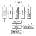
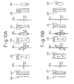
- Figure 1 is a block diagram showing the configuration of a concentration measuring apparatus according to a first embodiment of the present invention.
- reference numeral 1 is a light source which emits linearly polarized light and is constructed, for example, from a laser diode or the like.
- Reference numeral 2 is a sample for which the concentration of an optically active substance in a solution is to be measured by the apparatus of the present invention. If the sample is blood, and the optically active substance is sugar, then the analyte is dextroglucose.
- Reference numeral 3 is an optically active liquid crystal element, which is formed from a twisted nematic liquid crystal.
- a left-hand twisted nematic liquid crystal element is used, and when using it as an optical rotation adding type apparatus, a right-handed twisted nematic liquid crystal element is used.
- Reference numeral 4 is a linear polarizer
- 5 is a light detecting element constructed from a photodiode or a light receiving element
- 6 is a light intensity detection circuit.
- reference numeral 7 is a control circuit which, based on the detection value from the light detecting element 5, determines the voltage to be applied to the optically active liquid crystal element 3.
- Reference numeral 8 is a power supply circuit which, based on the output of the control circuit, supplies the necessary voltage to the optically active liquid crystal element 3 as well as the voltage necessary to drive the light source 1.
- Reference numeral 9 is a concentration computing circuit which, based on the control output of the control circuit 7, computes the concentration of the optically active substance in a solution.
- the power supply circuit 8 may be configured to supply the reverse-biasing voltage.
- the molecules of the optically active substance are oriented in a random manner in the sample 2, the polarization plane of the linearly polarized light emitted from the light source 1 is rotated while passing through the sample 2, and emerges as elliptically polarized light. Accordingly, when the twisted nematic liquid crystal element 3 is placed which produces an optical rotation in a direction opposite to the direction of rotation of the light emerging from the sample, the elliptically polarized light passing through the liquid crystal element 3 is modulated in a direction that rolls back the plane of polarization.
- the liquid crystal element is a right-hand 90-degree twisted nematic liquid crystal element and the applied voltage is 0 V, the sample here being pure water.
- the output intensity of the light detecting element 5 represents the brightest condition because the light was rotated through 90 degrees by the rotatory power of the twisted nematic liquid crystal element 3.
- the output intensity of the light detecting element 5 decreases because of the dextrorotatory nature of the solution.
- the optical rotation produced by the liquid crystal element 3 decreases, and when the voltage reaches the point where the total of the angle of optical rotation produced by the dextrorotatory solution and the angle of optical rotation produced by the liquid crystal element is equal to 90 degrees, the light becomes the brightest. Detecting the darkest condition can reduce design constraints compared with the case of detecting the brightest condition, because the circuit saturation problem can then be avoided; therefore, the polarizer is set at a position rotated 90 degrees.
- the applied voltage for the darkest condition must be determined by using a technique that approximates an easily analyzable function from many measured values in the neighborhood of the darkest point and computes the applied voltage that minimizes the approximated function.
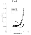
- the right-hand 90-degree twisted nematic liquid crystal element was used in combination with a D-glucose analyte solution, and the linear polarizer 4 was arranged with its plane oriented so as to produce the darkest condition with a pure water sample; then, the voltage applied to the twisted nematic liquid crystal element was varied so as to provide such an angle that produced the darkest condition with the pure water sample, without using a phase-correcting alignment liquid crystal element.
- the actually measured data in the above arrangement are shown in Figure 2
- the analytical curve derived from the data is shown in Figure 3 .
- the abscissa represents the voltage (V) applied to the twisted nematic liquid crystal element, and the ordinate represents the output (V) of the light intensity detection circuit.
- the abscissa represents the sugar concentration expressed as percent by weight, and the ordinate represents the liquid crystal driving voltage (V) that minimizes the light intensity. From this graph, it can be seen that the sugar concentration in the solution can be computed by the apparatus of Figure 1 by detecting the applied voltage to the optically active liquid crystal element 3 that minimizes the output of the light detecting element 5.
- the concentration computing circuit 9 in Figure 1 is a circuit which, based on the prestored data such as shown in Figure 3 , obtains the concentration of the optically active substance in a solution from the applied voltage to the optically active liquid crystal element 3 determined by the control circuit 7.
- the concentration can be measured in the same manner as described above.
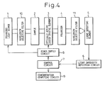
- FIG 4 is a block diagram showing the configuration of a concentration measuring apparatus according to a second embodiment of the present invention.
- This embodiment differs from the configuration shown in Figure 1 by the inclusion of a light wavelength selective filter 10 on the exit side of the light source 1 and a second wavelength selective filter 11, placed between the polarizer 4 and the light detecting element 5, for transmitting therethrough only the light passed through the wavelength selective filter 10.
- a light wavelength selective filter 10 on the exit side of the light source 1
- a second wavelength selective filter 11 placed between the polarizer 4 and the light detecting element 5, for transmitting therethrough only the light passed through the wavelength selective filter 10.
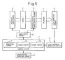
- FIG. 5 is a block diagram showing the configuration of a concentration measuring apparatus according to a third embodiment of the present invention.
- the control circuit 7 includes a modulating circuit 71 for modulating the light emitting intensity of the light source 1 with a particular code or frequency, a filter circuit 72 for extracting a modulated signal contained in the electrical output signal of the light intensity detecting element 5, and a timing circuit 73 for generating timing common to the respective circuits.
- the filter circuit 72 for detection the S/N ratio of the signal improves.
- FIG. 6 is a block diagram showing the configuration of a concentration measuring apparatus according to a fourth embodiment of the present invention.
- This embodiment differs from the configuration shown in Figure 5 in that a transmitter 12 and a receiver 13 are provided so as to be able to remotely control the sensor section comprising the light source 1, optically active liquid crystal element 3, light detecting element 5, light intensity detection circuit 6, control circuit 7, and power supply circuit 8.
- This configuration is suitable for applications where the concentration measuring apparatus of the invention is worn on a human body or implanted in the body.
- the light source 1, optically active liquid crystal element 3, polarizer 4, light detecting element 5, light intensity detection circuit 6, control circuit 7, power supply circuit 8, and transmitter 12 may be implanted in the human body, in which case the output of the control circuit 7 is transmitted via the transmitter 12 and the receiver 13 to the control and analysis apparatus external to the body.
- the burden on the human body can be alleviated.
- the control circuit 7 can be placed outside the human body.
- FIG. 7 is a functional block diagram for explaining the configuration of a fifth embodiment of the present invention.
- reference numeral 122 is a linearly polarized light source means.
- This light source means can be constructed, for example, by combining a light-emitting diode with a linear polarizer 102.
- a laser diode capable of emitting linearly polarized light may be used as the light source 101.
- the linear polarizer 102 can be omitted.
- Reference numeral 103 is an optically active sample
- 112 is an electro-optical optical rotation modulating means for compensating for the optical rotation given by the optically active sample
- 124 is a linearly polarized light intensity detecting means. If the sample 103 is human blood or a solution containing light-scattering particles, disturbance of the polarization or scattering of light occurs. Further, in the case of a body fluid, light transmittance varies as a function of time.
- the optical rotation compensating means is a means that performs a modulation for compensating for the angle of optical rotation and a phase compensating modulation for converting elliptically polarized light into linearly polarized light, in order that the light elliptically polarized by being subjected to the rotation angle modulation and birefringence in the sample can be detected with high S/N ratio (signal-to-noise ratio) by the light intensity detecting means 124.
- a liquid crystal element that exhibits a twisted structure in which the liquid crystal molecules are oriented in twisted fashion.
- the polarized component that matches the orientation direction of the substrate is allowed to enter and is rotated through an angle equal to the twist angle.
- the optical rotatory power decreases, and the angle of optical rotation changes. Utilizing this property, the angle of optical rotation is adjusted electrically.
- a parallel aligned liquid crystal element is used for the phase modulation.
- the orientation direction of the substrate is set at about 45 degrees with respect to the major axis of the elliptically polarized light, and the incident elliptically polarized is converted into linearly polarized light by adjusting the applied voltage to the liquid crystal element, and thereby adjusting the phase difference between the ordinary light and extraordinary light with the phase difference produced by the liquid crystal element.
- the elliptically polarized light is converted back to the linearly polarized light by using the parallel aligned liquid crystal element provided to adjust the phase difference between the two components of birefringent light.
- the linearly polarized light intensity detecting means 124 is constructed from a combination of a linear polarizer 106 and a light intensity detecting element 107. Light which has passed through the linear polarizer enters the light detecting element 107; with the light detecting element 107 which is independent of optical rotation, an output proportional to the intensity of the linearly polarized light can be obtained.
- the light detecting element use can be made of a reverse-biased silicon semiconductor PN junction element, a phototransistor element, a cadmium sulfide photoconductive element, or the like.
- the linear polarizer can be constructed using an inexpensive, commercially available 50% absorption-type linear polarizer.
- the above system in which the optical rotation modulation applied by the sample is compensated for by using the optical rotation modulating liquid crystal element and the phase modulating liquid crystal element, can be implemented as a system that uses a zero method in which the leakage light of detection light is detected and the compensation is performed so as to minimize the leakage light, or alternatively as a system that uses a maximum value tracking method in which the amount of light incident on the detecting element is detected and the compensation is performed so as to maximize the amount of incident light.
- the sample 103 is a human body part, such as a finger, an earlobe, or a portion of an arm, through which blood is flowing.
- the optical rotation control element 104 is an optical rotation controlling twisted liquid crystal element comprising a pair of transparent substrates disposed opposite each other and having transparent electrodes formed thereon, the substrates being treated to provide a low tilt angle close to an angle parallel to the substrates.
- the twist angle need not necessarily be set to 90 degrees, but can be set within a range from an angle approximately equal to the angle of optical rotation produced by the sample to about 360 degrees.
- the polarization plane of the light entering the liquid crystal element is rotated through an angle equal to the twist angle.
- the angle of the polarization plane of the entering light does not match the angle of the liquid crystal molecular orientation, optical rotation modulation and elliptical polarization occur at the same time because the component of light that matches the molecular orientation and the component of light orthogonal to it propagate at different velocities.
- the applied voltage is significantly higher than the threshold of the liquid crystal element, the liquid crystal molecules in the liquid crystal element are aligned perpendicularly to the substrates, so that the rotatory power is lost and the angle of optical rotation becomes 0.
- both the angle of optical rotation and the degree of elliptical polarization change according to the applied voltage.
- the parallel aligned liquid crystal element 105 is a liquid crystal element constructed by forming transparent electrodes on a pair of transparent substrates treated for alignment and arranged opposite each other with their alignment directions pointing in the same direction, and by injecting a liquid crystal material to fill the gap between the substrates.
- the applied voltage is 0, there arises a phase difference between the component of light parallel to the molecular orientation and the component of light orthogonal to it, and when a voltage higher than the threshold is applied between the transparent electrodes sandwiching the liquid crystal layer therebetween, the liquid crystal molecules are aligned perpendicularly to the substrates, so that the phase difference becomes 0.
- the applied voltage in terms of RMS is in the vicinity of the threshold, the degree of the phase difference varies depending on the applied RMS voltage.
- the RMS voltage applied to each liquid crystal element is adjusted so that the light rotated and elliptically polarized by passing through the sample 103 will be rotated back to its original orientation, i.e., the linearly polarized light, when passed through the optical rotation compensating element 104 and the phase control element 105.
- the angle of optical rotation may be increased so as to provide an angle orthogonal to the polarization plane of the output light of the linearly polarized light source 122.
- the linear polarizer 106 is arranged with its plane oriented at right angles to the polarization plane of the light passed through the polarizer 102 and the optical rotation control element in the absence of an applied voltage so that the amount of transmitted light is a minimum when the sample 103 is removed.
- One optical rotation measuring method is the zero method in which the photocurrent from the light detecting element 107 is converted to a voltage, and the optical rotation control element 104 and the phase control element 105 are controlled through negative feedback of the RMS (Rout-mean-square value or effective value) voltage for driving each control element so that the output voltage value becomes a minimum.
- RMS Raster-mean-square value or effective value
- the polarizers 102 and 106 are arranged with their polarization planes oriented parallel to each other so that the amount of transmitted light is maximum when the sample 103 is removed, and the voltages to be applied to the phase modulating liquid crystal element and the optical rotation modulating liquid crystal element are adjusted through feedback control of the RMS voltages for driving the phase control element 105 and the optical rotation control element 104 so that the output current of the light detecting element 107 becomes a maximum for measurement when the sample is introduced.
- the first method has the advantage of being able to achieve a highly accurate measurement when there is relatively little external disturbing light
- the second method has the advantage of being able to perform control using a large signal voltage from the electrical circuit when the amount of light from the light source is small.
- the effects of external disturbing light can be eliminated by varying the amount of light from the light source as a function of time and amplifying the resulting difference.
- the effects of external disturbing light include a saturation of the light detecting element 107 or a saturation resulting from an excessively large input to the differential amplifier circuit, and from the standpoint of increasing the S/N ratio, it will be effective to increase the power of the light source 101, within a range that does not cause a saturation, so that the light will not be buried under external light.
- the differential amplifier circuit In a configuration where the differential amplifier circuit is operated in a time division fashion, the voltage level of the light detection signal obtained when the power of the light source is set to a small value L0 is stored as S0 in a sample-and-hold circuit, and the voltage level of the light detection signal obtained when the power of the light source is increased to L1 is denoted by S1; then, when the signals S1 and S0 are coupled to the two differential inputs of the differential amplifier circuit, the difference is detected and amplified. With this method, the effects of the external disturbing light can be alleviated.
- an AC amplifier circuit can be utilized, and the technique of a lock-in amplifier having a good S/N ratio that performs frequency filtering can be used to allow only the frequency of the amplified signal near the time modulating signal component to pass through, thereby detecting the signal synchronously with the frequency.
- the blood in a living human body is pulsating, from the standpoint of increasing the S/N ratio of sugar detection it is effective to extract pulsating components from the time variation of the detected light intensity and to sample the sugar concentration synchronously with the pulsation frequency.
- the various methods described above are one embodiment of bio-signal filtering.
- it is effective to use low-power oscillation by a crystal oscillator and signal processing by a CMOS integrated circuit, in combination with a low-power display by a liquid crystal display device and an alarm indication by voice.
- optical rotation reverse compensating liquid crystal element 104 and the phase compensating liquid crystal element for converting the elliptically polarized light back to linearly polarized light may be placed before the sample 103.
- Figure 8 is a block diagram showing the configuration of a concentration measuring apparatus according to a sixth embodiment of the present invention.
- Reference numeral 222 is a linearly polarized light source
- 201 is a light-emitting element
- 202 is a linear polarizer which can be omitted if the light-emitting element 201 is a laser diode.
- Reference numeral 204 is an optical rotation control element; the orientation direction of the liquid crystal molecules in the optical rotation control element is aligned with the polarization plane of the linearly polarized light source.
- the output of the optical rotation control element 204 is linearly polarized light whose polarization plane is rotated through an angle equal to the twist angle when the applied voltage is 0; the angle of rotation of the polarization plane decreases as the applied voltage increases.
- the driving voltage of the optical rotation control element 204 is adjusted so that the angle of polarization plane rotation produced by the optical rotation control element 204 becomes equal in magnitude but opposite in sign to the angle of optical rotation produced by the sample 203.
- the polarization plane of the light passed through the optical rotation control element 204 and emerging from the sample 203 is corrected and oriented so as to contain the polarization plane of the light source 222 as well as the optical axis thereof, but the light is elliptically polarized.
- the elliptically polarized light can be adjusted by adjusting the driving voltage applied to the phase modulating element 205.
- the phase modulating element 205 is arranged with its plane oriented at 45 degrees relative to the polarization plane of the light source.
- Figure 9 is a block diagram showing the configuration of a concentration measuring apparatus according to a seventh embodiment of the present invention.
- Reference numeral 322 is a linearly polarized light source
- 301 is a light-emitting element
- 302 is a linear polarizer which can be omitted if the light-emitting element 301 is a laser diode.
- Reference numeral 304 is an optical rotation control element; the orientation direction of the liquid crystal molecules in the optical rotation control element is aligned with the polarization plane of the linearly polarized light source.
- the optical rotation control element 304 On the output side of the optical rotation control element 304 is placed a phase control element so that the linearly polarized light emerges as elliptically polarized light from the latter; here, the optical rotation control element 304 and the phase control element 305 are controlled so that the light emerging from the sample 303 is close to linearly polarized light.
- the light elliptically polarized by passing through the two control elements is made close to linearly modulated light by passing through the sample 303, and the angle of optical rotation is detected.
- Reference numeral 306 is a linear polarizer
- 307 is a light detecting element
- 324 is a linearly polarized light detecting means.
- the driving voltage of the optical rotation control element 304 is adjusted so that the angle of polarization plane rotation produced by the optical rotation control element 304 becomes equal in magnitude but opposite in sign to the angle of optical rotation produced by the sample 303.
- the polarization plane of the light passed through the optical rotation control element 304 and emerging from the sample 303 is corrected and oriented so as to contain the polarization plane of the light source 322 as well as the optical axis thereof, but the light is elliptically polarized.
- the elliptically polarized light can be adjusted to linearly polarized light by adjusting the driving voltage applied to the phase modulating element 305.
- the phase modulating element 305 is arranged with its plane oriented at 45 degrees relative to the polarization plane of the light source.
- the output light 428 from the linearly polarized light source is passed through the linear polarizer 421 and enters the optical rotation control element 422 where the angle of the polarization plane is adjusted before entering the sample 423; as a result of the compensation, the plane of polarization is oriented in the same direction as that of the light source output light 428, and the resulting elliptically polarized light is corrected by a birefringence phase difference modulating element 424 into linearly polarized light which is then passed through the linear polarizer 425 and detected by the light detecting element 426 where the light intensity is detected.
- the angle of optical rotation, ⁇ (v), produced by the optical rotation compensating element is a function of the driving voltage e1 of the optical rotation controlling liquid crystal element 204.
- the rotation position of the polarizer is chosen so as to enhance the control sensitivity and is set so that the amount of transmitted light becomes 0 when the optical rotation produced by the sample is 0. Accordingly, the initial position of the rotation angle of the polarizer 206 is ⁇ 0 + 90 degrees ⁇ .
- the concentration, x, of the optically active sample increases, i.e., x > 0, and the angle of optical rotation, ⁇ s, of the light passed through both the rotatory power compensating element 204 and the sample 203 becomes larger than ⁇ 0, the electrical output of the light detecting element 207 is then Vdt > 0.
- the voltage e1 for driving the optical rotation controlling liquid crystal element 204 is created by amplifying Vdt, and a negative feedback is applied.
- Vdt is amplified to create the voltage e1 for driving the optical rotation controlling liquid crystal element 204, and when e1 is increased to reduce Vdt down to 0, ⁇ s0 drops below the minimum point and, after that, the control enters a positive feedback region in which Vdt increases with increasing e1.
- the compensating control operation is performed by preliminarily adjusting the output of the linearly polarized light detecting means 224 by controlling the optical rotation control element 204 and the phase compensating element 205 in sequence.
- an e1 point at which Vdt is minimum is found by successively increasing and decreasing the driving voltage and, at that point, an extreme value e2 at which Vdt is minimum is found, this time by successively increasing and decreasing the driving voltage of the phase control element 205; next, e1 and e2, where Vdt is minimum, are fine-adjusted.
- the angle of optical rotation is proportional to the sugar concentration in the sample and the light path length of the sample.
- the simplest way to maintain the light path length constant is to fix the physical dimensions of the sample in Figure 1 . Further, in order to keep control of the amount of blood in the fixed volume of the sample, if the amount of attenuation of light passing through the sample is measured, and the angle of optical rotation is divided by the amount of attenuation, the effects of the variation of the blood amount in the body part being measured can be reduced.
- the laser diode is a red light emitting type, it is effective to attach to the front of the polarized light intensity detecting element a means that blocks light of other wavelengths than the red light.
- a filter is used that blocks or absorbs light of wavelengths shorter than the wavelength of that light source.
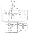
- FIG 11 shows the configuration of a control system for the measurement of optically active substance concentration according to one embodiment of the present invention.
- the entire system comprises: a linearly polarized light source 504 which includes a laser diode; an optical rotation controlling liquid crystal element 506; a phase modulating liquid crystal element 508; a light detecting means 510 constructed from a combination of a linear polarizer and a light detecting element; a drive control circuitry 516 for frequency- or code-modulating the laser diode in the linearly polarized light source 504; a drive circuitry 502 for driving the laser diode; a detection circuitry 518 for analyzing an output signal of the light detecting means 510, and for extracting optical rotation information; a liquid crystal drive circuitry 512 for driving the optical rotation controlling liquid crystal element 506 and the phase modulating liquid crystal element 508; and an oscillator circuitry 514 for providing a common time reference which is used in common for controlling the drive circuitries 502 and 512 and the detection circuitry 518.
- the drive control circuitry 516 Based on the clock signal of a constant and accurate frequency created by the oscillator circuitry 514 constructed from a crystal oscillator circuit, etc. the drive control circuitry 516 creates a control signal for modulating the output light of the linearly polarized light source 504, and drives the light source 504 via the light source driving circuit 502.
- the detection circuitry 518 which extracts optical rotation information by using the synchronized time reference signal created by the same oscillator 514, the detection signal of the light detecting means 510 is analyzed, and the optically active sample concentration is computed.
- the detection signal component can be extracted with a high S/N ratio by, for example, frequency-modulating the light source 504 in accordance with a predefined rule, by extracting in the detection circuitry 518 the detection signal through a narrowband extraction filter matched to the light source modulating frequency, and by detecting the signal in synchronism with a clock signal of the same frequency.
- the method of synchronous detection and the method of coded modulation/demodulation are effective in measuring the concentration of the optically active substance by eliminating the effects of the various electrical noise and optical noise that the person under examination encounters, and the generation and utilization of the common clock signal is also effective.
- Figure 12 shows an example in which the sugar concentration detection apparatus of the invention is worn on a human body.
- a mechanical member that can clamp a body part at a constant thickness.
- the sample is clamped using a spring mechanism such as a clothespin; in this case, a protrusion or a clamp member for limiting the clamp travel distance is provided on the spring side or the clamping side, to maintain the thickness of the clamped part substantially constant.
- reference numeral 602 is a concentration measuring apparatus which is clamped on the earlobe
- 604 is a module in which a polarized light emitting element and a polarized light detecting element are integrated; the opposite side of the clamping member is a mirrored surface. Polarized light emitted from the light emitting element is passed through the body part and reflected by the mirrored surface, and the reflected light is again passed through the body part and enters the polarized light detecting element.
- Reference numeral 608 is a circuit module which contains a signal processing circuit, a power supply cell, and a wireless transmitter, and is incorporated in the earlobe clamp-type concentration measuring apparatus.
- Reference numeral 606 is the earlobe.
- Reference numeral 610 is a clothespin-like member for clamping the earlobe
- 612 is a spring which generates the clamping force.
- the advantage of the earlobe clamp-type apparatus is that not only is the blood circulation through the earlobe relatively constant, but the apparatus does not cause any nuisance to the person who wears it on the earlobe.
- the apparatus may be worn on some other part of the body, such as the belly or a leg or an arm, that is covered by clothes.
- the measurement is made intermittently at predetermined intervals of time or at predetermined times under control of a clock, and the measured data are stored and are read out for use as necessary.
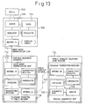
- Figure 13 shows an example of the system configuration when the sugar concentration detection apparatus of the invention is worn on a human body.
- the sensor section is made up of the minimum necessary number of components including the power supply, and the collected detection information is transmitted to the main portable apparatus via a short-range wireless link.
- the main portable apparatus is constructed to be able to send the information via a public wireless telephone network to a patient biological information data bank so that the doctor can diagnose the information.
- reference numeral 708 is a sensor module and, more specifically, is a wireless detection module, such as an earlobe clamp-type module like the one shown in Figure 12 or a bracelet-type or bellyband-type module.
- Reference numeral 702 is a sample
- 706 is the optically active substance concentration detecting element of the present invention
- 704 is a built-in clock which is synchronized to the clock incorporated in the main portable apparatus 712.
- Reference numeral 714 is a short-range communication link that uses weak radio waves or low-frequency magnetic waves lower than 10 kHz.
- Reference numeral 716 is a short-range receiver incorporated in the main portable sensing apparatus, and 718 is a main processing unit which includes a signal analyzer/processor and a wireless transmission/reception interfacing unit for interfacing with the public wireless telephone network.
- Reference numeral 728 is the public wireless telephone network
- 724 is a hospital system equipped with a patient tracking management/diagnosis function.
- the hospital system is also equipped with a hospital wireless base station function that uses the public wireless telephone network, so that the system can be linked to a large number of portable test apparatuses and can provide services when accessed by patients or monitor and manage contracted patients conditions by tracking the patients.
- the communication base station function can be entrusted to a telephone company.
- biosensing is not limited to localized symptomatic therapy, but can be linked with an information analysis/comparison diagnostic system to provide additional benefits. It is also possible to achieve a mechanism that does not impose excessive functional or energy loads to the sensing module.
- the concentration detection system of the present invention that does not use any moving parts allows an extremely small and low-power construction, and is suited for application to a wearable wireless concentration detection apparatus or an implantable blood sugar concentration detection apparatus. The measurement is made intermittently, or by controlling the measurement period, to reduce average power consumption.
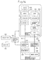
- FIG 14 shows an example of the system configuration when the sugar concentration detection apparatus of the invention is implanted in a human body.
- one configuration example of the implantable blood sugar concentration detection apparatus is shown.
- Reference numeral 802 is a sample
- 808 is the detection apparatus
- 806 is a sensor element
- 804 is a built-in clock
- 822 is a secondary battery
- 824 is a charge coil.
- Reference numeral 844 is a sugar level monitoring apparatus external to the human body.
- the apparatus 844 is an information exchange apparatus that also serves as a battery charger, and is placed outside the human body.
- Reference numeral 834 is a low-frequency magnetic wave generator which generates magnetic waves lower in frequency than 10 kHz, and supplies electrical energy to the implanted sensor apparatus 850.
- Reference numeral 836 is an energy source for the battery charger, which derives power from a battery or a commercial power supply.
- Reference numeral 838 is a data analysis/alarm device which analyzes biological data input via a transmitter/receiver 828, and issues an alarm if the data indicates any abnormality in the human body; this device has a built-in clock which is synchronized to the clock built in the implanted sensor apparatus.
- the alarm condition may be indicated using, for example, a display device or by means of voice or vibration.
- the transmitter/receiver 828 transmits information to the implanted apparatus by using weak electromagnetic waves, and collects information from the apparatus.
- Reference numeral 814 is a short-range communication link.
- the implanted sensor apparatus 850 constantly measures blood sugar concentration in vivo via a titanium metal case or a sapphire or silica light path that does not cause an allergic reaction on human body, and the implanted apparatus can transmit the results of the measurements in a safe manner to the apparatus outside the human body.
- an automatic injection device 860 and insulin and sugar spare reservoirs 862 and 864 are added in the above system, an injection of insulin or sugar can be automatically administered in an emergency situation.
- the automatic injection device and the insulin and sugar spare reservoirs are placed outside the human body and, depending on the biological information received from the implanted sensor apparatus 850, the data analysis/alarm device 838 in the sugar level monitoring apparatus 844 issues an alarm to the patient via the transmitter/receiver 828 or drives the automatic injection device 860 to automatically administer an injection of insulin or sugar.
- the sugar level monitoring apparatus 844 may be configured to monitor the implanted sensor apparatus 850 at predetermined intervals of time and to issue an alarm or drive the automatic injection device if any abnormality is detected.
- Figure 15 shows one example of the characteristic of the optical rotation control element used in the present invention.
- the graph here shows the characteristic when AC pulses of 32 kHz are applied to the liquid crystal element that exhibits a 45-degree twisted structure at an applied voltage of 0.
- the applied voltage is not higher than 1.5 V
- the liquid crystal produces an optical rotation of 45 degrees, but when the drive voltage exceeds 1.5 V, the angle of optical rotation monotonically decreases until the voltage reaches about 2 V.
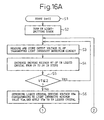
- Figure 16 is a flowchart illustrating a procedure for measuring sugar concentration in a solution by using the concentration measuring apparatus shown in Figure 1 .
- Figure 16A shows the first half of the flowchart, and Figure 16B shows the second half.
- the concentration measuring procedure will be described below with reference to the flowchart.
- the laser diode i.e., the linearly polarized light source
- the laser diode is placed in position and, on the upstream side of the light source as viewed in the light emitting direction, a transparent container containing an analyte solution is placed with its plane perpendicular to the output light of the diode.
- the angle of the linear polarization plane of the laser light is tentatively assumed to be 0 degree.
- the container containing the dextrorotatory analyte solution is followed by a - ⁇ -degree twisted nematic liquid crystal element having a left-hand twisted structure.
- the - ⁇ -degree twisted nematic liquid crystal element is followed by a linear polarizer whose polarization plane is oriented at right angles to the polarization plane of the exit polarizer of the - ⁇ -degree twisted nematic liquid crystal element, and a light detecting element is placed on the exit side of the linear polarizer.
- the detection light is blocked by the twisted nematic liquid crystal element when the applied voltage is 0; at this time, the light detection circuit is outputting a signal indicating a light intensity level of 0. (The value of this 0-level signal is stored as VL0 in a storage circuit.) In this condition, an analyte solution is introduced into the container.
- the concentration measurement is started in step S1 in Figure 16 .
- various memories in the measuring apparatus are initialized.
- counter value n is set to 0.
- step S2 the light-emitting diode is turned on, and various initial values of the measuring system are checked and stored. Then, in step S3, the output value VL of the light measuring circuit is measured, and its initial value VL0 is stored.
- the measured value VL is stored with the applied voltage VT as its address value.
- the plane of polarization is rotated through ⁇ degrees, and elliptical polarization also occurs, causing leakage of light.
- the applied voltage to the - ⁇ twisted nematic liquid crystal element is increased, the - ⁇ optical rotation component decreases, and as a result, the light emerging from the liquid crystal element is elliptically polarized light.
- the light component passing through the linear polarizer first decreases due to the above effect and, then, increases.
- the applied voltage to the twisted nematic liquid crystal element at which the transmitted light takes a minimum value increases with increasing sugar concentration.
- the twisted nematic liquid crystal drive voltage VTm at which the measured value takes a minimum value has almost been determined. Due to measurement errors, it is not easy to accurately determine the twisted nematic liquid crystal drive voltage at which the transmitted light takes a minimum value.
- a relatively simply method is to make use of the fact that the step size with which the drive voltage is incrementally increased is predetermined, and to apply smoothing in which a moving average of the liquid crystal drive voltage at 21 neighboring points is taken and the measured light intensity value corresponding to that average value is determined as the corrected measured value of the 11th point located at the midpoint of the 21-point span; then, the drive voltage that minimizes the corrected measured value is defined as the twisted nematic liquid crystal drive voltage VTm that yields the light intensity minimum value VLm, and this voltage value VTm is applied to the twisted nematic liquid crystal element (step S6).
- the liquid crystal element When the liquid crystal element is thus set to minimize the amount of transmitted light as described above, if a phase modulating liquid crystal element is placed between the twisted nematic liquid crystal element and the polarizer to adjust the phase difference, the minimum value of the transmitted light further decreases.
- This phase compensation is applied in order to enhance the accuracy when determining the minimum value of the light transmittance of the twisted nematic liquid crystal, but in the case of an apparatus that does not use the phase modulating liquid crystal element, for example, the apparatus of the first embodiment shown in Figure 1 , the following step X is omitted.
- step X of obtaining the optimum phase modulation voltage VPm the output voltage VL of the light detection circuit when the twisted nematic liquid crystal drive voltage is VTm is stored in step S7.
- steps S8 to S10 the voltage VP applied to the phase modulating liquid crystal element is increased in steps from 0 V to 6 V, and the voltage value VPm at which the output voltage VL takes a minimum value is detected and is applied to the phase modulating liquid crystal element.
- step S11 the number of measurements, n, is stored together with the voltage value VTm(n) and output voltage value VLm(n) obtained in the above steps.
- step S12 the degree of convergence is checked. More specifically, in the (n-1)th and n-th measurements, VLm(n) - VLm(n-1) is obtained, and the measurement is repeated until the obtained value converge within a predetermined error ⁇ . That is, as long as the data of the twisted nematic liquid crystal drive voltage VTm that maintains the transmitted light at a minimum varies greatly between measurements as the number of measurements, n, increases, the process returns to step S3 to repeat the measurement, and when the result of the measurement has settled within the predetermined error ⁇ , the measurement is stopped (Yes in step S12).
- step S13 the value of the applied voltage VTm at that instant in time is store as "VTme", and in step S14, the sugar solution concentration corresponding to the value VTme is computed from a mapping table of value VTme and sugar concentration. In step S15, the sugar concentration data G thus computed is output.
- noise signals superimposed on measured values, light intensity measurement errors, variations in the position of the sensor worn on the human subject, and light noise from outside the human body are the factors that limit the sugar concentration measurement.
- smoothing operations based on time averages and averaging operations appropriate to the conditions near the measured values are performed.
- the moving average method while the liquid crystal drive voltage is being swept from 0 V to 20 V in 200 steps each with a step size of 10 mV, the average of neighboring 11 data points is taken and the sixth data point located at the midpoint of the 11-point span is replaced by the average value of the neighboring 11 data points; when this moving average method is used, data from the sixth data point to the 194th data points are replaced by the data smoothed by the above moving average process.
- Each moving average data has about one-tenth of the error occurring at the time of the measurement. As the point here is not to obtain the minimum value itself but to accurately determine the value of the applied voltage that yields the minimum value, the above smoothing is effective in eliminating the effects of sporadic noise.
- the minimum value can be computed in a simple manner, based on the smoothed data.
- the above measuring procedure can be applied to a system in which a laser light emitting element and a laser light reflecting member are mounted on a toilet stool and the reflected light is detected by a twisted nematic liquid crystal element and a light detecting element to measure the angle of optical rotation. Since the flush toilet is flushed every time it is used, and since there always remains a certain amount of water in the toilet bowl, the degree of dilution of urine can be estimated by measuring the water level, and the sugar concentration can thus be corrected.
- a liquid crystal element exhibiting a twisted structure can be used as an electronically controllable optically active element, since it has an ability to rotate the component of light that lies along the principal axis of the molecular orientation.
- the light is elliptically polarized; therefore, the elliptically polarized light can be converted into linearly polarized light by using a parallel aligned liquid crystal element that controls the phase difference between the two birefringent components.
- the elliptically polarized light can be converted into linearly polarized light by electrically adjusting the phase difference between the major axis and minor axis components of the elliptically polarized light by utilizing the velocity difference between the major axis component and the minor axis component propagating at different velocities through the parallel aligned liquid crystal element.
- the concentration of an optically active substance dissolved in a solution can be measured in a relative manner. Even in the case of the measurement of optical rotation buried in noise, such as the measurement of blood sugar concentration in a human body, information concerning the plane of polarization can be extracted as it is different from light intensity information.
- the apparatus of the invention When using the apparatus of the invention as a health management support tool for an individual, if the individual can check the condition of his health against his normal healthy condition, it will suffice the purpose of health management even if the measurement contains a certain degree of error. Blood sugar detection by electronic control of the optically active liquid crystal element allows a compact and low-power construction, and is suited for a wearable or implantable apparatus.
- a wavelength filter that transmits only the wavelength of the measuring laser light source and blocks or absorbs other wavelengths that degrade the sensitivity of the measurement. Furthermore, by also using software processing based on a coded time averaging method and thereby improving the signal-to-noise ratio of the measurement, polarization component information buried in noise, from the blood under the skin, can be extracted.
- sugar concentration in urine, etc. can be measured in a simple way by using the method of the present invention. If the measuring apparatus of the invention is adapted to be implantable in a human body, blood sugar concentration can be measured accurately, which is very useful.
- the invention achieves a sugar concentration measuring apparatus having excellent portability and compact in construction.
- the low-power design allows the construction of a wearable or implantable apparatus. As there is no moving part, the apparatus does not generate dust and is capable of stable operation over an extended period of time.
Landscapes
- Health & Medical Sciences (AREA)
- Life Sciences & Earth Sciences (AREA)
- Physics & Mathematics (AREA)
- General Health & Medical Sciences (AREA)
- Pathology (AREA)
- Biomedical Technology (AREA)
- Veterinary Medicine (AREA)
- General Physics & Mathematics (AREA)
- Immunology (AREA)
- Public Health (AREA)
- Animal Behavior & Ethology (AREA)
- Surgery (AREA)
- Biophysics (AREA)
- Engineering & Computer Science (AREA)
- Molecular Biology (AREA)
- Heart & Thoracic Surgery (AREA)
- Medical Informatics (AREA)
- Chemical & Material Sciences (AREA)
- Spectroscopy & Molecular Physics (AREA)
- Analytical Chemistry (AREA)
- Biochemistry (AREA)
- Optics & Photonics (AREA)
- Audiology, Speech & Language Pathology (AREA)
- Dentistry (AREA)
- Oral & Maxillofacial Surgery (AREA)
- Vascular Medicine (AREA)
- Investigating Or Analysing Materials By Optical Means (AREA)
- Measurement Of The Respiration, Hearing Ability, Form, And Blood Characteristics Of Living Organisms (AREA)
Applications Claiming Priority (3)
| Application Number | Priority Date | Filing Date | Title |
|---|---|---|---|
| JP2000342989 | 2000-11-10 | ||
| JP2000342989A JP4523143B2 (ja) | 2000-11-10 | 2000-11-10 | 濃度測定装置及び糖度測定装置 |
| PCT/JP2001/008589 WO2002038048A1 (en) | 2000-11-10 | 2001-09-28 | Concentration measuring instrument |
Publications (3)
| Publication Number | Publication Date |
|---|---|
| EP1332720A1 EP1332720A1 (en) | 2003-08-06 |
| EP1332720A4 EP1332720A4 (en) | 2007-10-31 |
| EP1332720B1 true EP1332720B1 (en) | 2010-06-09 |
Family
ID=18817434
Family Applications (1)
| Application Number | Title | Priority Date | Filing Date |
|---|---|---|---|
| EP01970294A Expired - Lifetime EP1332720B1 (en) | 2000-11-10 | 2001-09-28 | Concentration measuring instrument |
Country Status (6)
| Country | Link |
|---|---|
| US (1) | US7084976B2 (enExample) |
| EP (1) | EP1332720B1 (enExample) |
| JP (1) | JP4523143B2 (enExample) |
| CN (1) | CN1192745C (enExample) |
| DE (1) | DE60142353D1 (enExample) |
| WO (1) | WO2002038048A1 (enExample) |
Families Citing this family (36)
| Publication number | Priority date | Publication date | Assignee | Title |
|---|---|---|---|---|
| JP2004077466A (ja) | 2002-06-17 | 2004-03-11 | Citizen Watch Co Ltd | 濃度測定装置および濃度測定方法 |
| JP3966796B2 (ja) * | 2002-09-26 | 2007-08-29 | 真人 中村 | 血糖測定装置 |
| CN1768258B (zh) * | 2003-03-28 | 2010-10-13 | 西铁城控股株式会社 | 旋光度测量装置 |
| JP2005031840A (ja) * | 2003-07-09 | 2005-02-03 | Seiko Instruments Inc | 緊急通報装置 |
| ES2387569T3 (es) * | 2004-01-13 | 2012-09-26 | The University Of Toledo | Polarímetro sensor compensado por birrefringencia no invasivo |
| US8128871B2 (en) | 2005-04-22 | 2012-03-06 | Alverix, Inc. | Lateral flow assay systems and methods |
| US20070185679A1 (en) * | 2004-04-01 | 2007-08-09 | Petruno Patrick T | Indicating status of a diagnostic test system |
| US20060019331A1 (en) * | 2004-07-20 | 2006-01-26 | Gideon Eden | Method and system for generating a telephone alert indicating the presence of an analyte |
| US6970241B1 (en) * | 2004-08-24 | 2005-11-29 | Desa Richard J | Device for enabling slow and direct measurement of fluorescence polarization |
| JP4269079B2 (ja) * | 2004-11-01 | 2009-05-27 | 株式会社エイムテクノロジー | 散乱媒質中微量成分濃度の無侵襲測定装置 |
| RU2295915C2 (ru) * | 2005-02-18 | 2007-03-27 | Тахир Хусанович Холматов | Способ неинвазивного измерения концентрации оптически активных веществ, находящихся в крови |
| US10041941B2 (en) | 2005-04-22 | 2018-08-07 | Alverix, Inc. | Assay test strips with multiple labels and reading same |
| JP2007046943A (ja) * | 2005-08-08 | 2007-02-22 | Tokyo Univ Of Agriculture & Technology | 観測装置、観測方法、ファラデー回転角測定方法、ファラデー楕円率測定方法、カー回転角測定方法及びカー楕円率測定方法 |
| CN104162200B (zh) | 2006-02-09 | 2018-03-27 | 德卡产品有限公司 | 外围系统 |
| US20080068932A1 (en) * | 2006-09-14 | 2008-03-20 | Bennie Mosley | Wrist watch for monitoring diabetes |
| US8032472B2 (en) * | 2007-04-04 | 2011-10-04 | Tuen Solutions Limited Liability Company | Intelligent agent for distributed services for mobile devices |
| US20130006077A1 (en) * | 2007-04-24 | 2013-01-03 | Hsueh-Kuan Lu | Method for measuring blood flow velocity |
| US8094307B2 (en) | 2007-07-05 | 2012-01-10 | Baxter International Inc. | Method and apparatus for measuring the presence and concentration of pharmaceutical substances in a medical fluid administered by a medication delivery system |
| WO2009032969A1 (en) * | 2007-09-06 | 2009-03-12 | Smith & Nephew, Inc. | System and method for communicating with a telemetric implant |
| EP2318831A4 (en) * | 2008-07-22 | 2014-03-26 | Jaafar Tindi | MANUAL APPARATUS FOR DETERMINING THE VIABILITY OF A BIOLOGICAL TISSUE |
| JP4977671B2 (ja) * | 2008-09-22 | 2012-07-18 | 株式会社アタゴ | 偏光変調器及び計測装置 |
| CN101852721B (zh) * | 2010-05-18 | 2012-06-27 | 南京邮电大学 | 两种溶质透明混合溶液浓度检测装置 |
| CN101893548A (zh) * | 2010-07-01 | 2010-11-24 | 上海理工大学 | 一种基于液晶器件的新型智能旋光仪及测试方法 |
| CN102600967A (zh) * | 2012-03-06 | 2012-07-25 | 南昌大学 | 一种智能控制磁分离器 |
| US9097647B2 (en) * | 2012-08-08 | 2015-08-04 | Ut-Battelle, Llc | Method for using polarization gating to measure a scattering sample |
| JP2014130046A (ja) * | 2012-12-28 | 2014-07-10 | Seiko Epson Corp | 旋光度測定方法、成分濃度測定方法、旋光度測定装置及び医療機器 |
| CN103385695B (zh) * | 2013-07-19 | 2016-04-13 | 武汉昊博科技有限公司 | 多波长肝脏储备功能检测仪及检测icg浓度的方法 |
| KR101644623B1 (ko) | 2013-10-29 | 2016-08-01 | 서울대학교산학협력단 | 포지티브 피드백을 이용한 수질 센서 |
| JP6435532B2 (ja) * | 2014-06-02 | 2018-12-12 | 株式会社アタゴ | 旋光度及び屈折率の測定装置 |
| KR101671400B1 (ko) * | 2015-03-18 | 2016-11-02 | 주식회사 지파랑 | 포지티브 피드백을 이용한 센싱 시스템 |
| KR102673720B1 (ko) * | 2016-07-29 | 2024-06-07 | 삼성전자주식회사 | 혈중 물질 추정 장치 및 방법 |
| WO2020017028A1 (ja) * | 2018-07-20 | 2020-01-23 | 桐生電子開発合同会社 | 非破壊検査装置 |
| JP6600842B2 (ja) * | 2018-10-16 | 2019-11-06 | 株式会社アタゴ | 旋光度及び屈折率の測定装置 |
| JP7197205B2 (ja) * | 2018-11-28 | 2022-12-27 | 学校法人明治大学 | 濃度測定装置、濃度測定方法及び非一時的記録媒体 |
| GB2633092A (en) | 2023-09-01 | 2025-03-05 | Univ Tartu | A system and method for sensing drinks |
| WO2025199535A1 (en) * | 2024-03-22 | 2025-09-25 | ViiT Health, Inc. | Systems and methods for non-invasive identification of biomarkers |
Family Cites Families (14)
| Publication number | Priority date | Publication date | Assignee | Title |
|---|---|---|---|---|
| JPS5817342A (ja) * | 1981-07-23 | 1983-02-01 | Horiba Ltd | 糖分分析計 |
| US5009230A (en) * | 1988-05-31 | 1991-04-23 | Eol, Inc. | Personal glucose monitor |
| US5209231A (en) * | 1990-11-02 | 1993-05-11 | University Of Connecticut | Optical glucose sensor apparatus and method |
| US5303709A (en) * | 1991-12-16 | 1994-04-19 | Dreher Andreas W | Retinal eye disease diagnostic system |
| EP0663604A1 (en) * | 1994-01-03 | 1995-07-19 | AT&T Corp. | Polarization rotator |
| US6049518A (en) * | 1995-08-31 | 2000-04-11 | Sanyo Electric Co., Ltd. | Optical disc recording/reproducing apparatus recording/reproducing information to/from optical discs according to different standards |
| WO1997018470A1 (en) * | 1995-11-16 | 1997-05-22 | Matsushita Electric Industrial Co., Ltd. | Method and apparatus for urinalysis, method of measuring optical rotation and polarimeter |
| JP3072040B2 (ja) * | 1995-11-29 | 2000-07-31 | 松下電器産業株式会社 | 旋光度測定方法、旋光計、尿検査方法及び尿検査装置 |
| JP3014633B2 (ja) * | 1995-11-16 | 2000-02-28 | 松下電器産業株式会社 | 尿検査方法 |
| US5788632A (en) * | 1996-03-19 | 1998-08-04 | Abbott Laboratories | Apparatus and process for the non-invasive measurement of optically active compounds |
| JPH10108857A (ja) * | 1996-10-04 | 1998-04-28 | Hitachi Ltd | 生化学計測装置 |
| DE60020453T2 (de) * | 1999-06-29 | 2006-05-11 | Matsushita Electric Industrial Co., Ltd., Kadoma | Polarimetrieverfahren sowie dessen Verwendung für die Harnanalyse |
| US6370407B1 (en) * | 1999-07-27 | 2002-04-09 | Tecmed, Incorporated | System for improving the sensitivity and stability of optical polarimetric measurements |
| IL136673A0 (en) * | 2000-06-11 | 2001-06-14 | Orsense Ltd | A method and device for measuring the concentration of glucose or other substance in blood |
-
2000
- 2000-11-10 JP JP2000342989A patent/JP4523143B2/ja not_active Expired - Fee Related
-
2001
- 2001-09-28 CN CN01818611.4A patent/CN1192745C/zh not_active Expired - Fee Related
- 2001-09-28 WO PCT/JP2001/008589 patent/WO2002038048A1/ja not_active Ceased
- 2001-09-28 EP EP01970294A patent/EP1332720B1/en not_active Expired - Lifetime
- 2001-09-28 US US10/416,200 patent/US7084976B2/en not_active Expired - Fee Related
- 2001-09-28 DE DE60142353T patent/DE60142353D1/de not_active Expired - Lifetime
Also Published As
| Publication number | Publication date |
|---|---|
| CN1192745C (zh) | 2005-03-16 |
| JP2001356089A (ja) | 2001-12-26 |
| DE60142353D1 (de) | 2010-07-22 |
| EP1332720A4 (en) | 2007-10-31 |
| EP1332720A1 (en) | 2003-08-06 |
| JP4523143B2 (ja) | 2010-08-11 |
| CN1473021A (zh) | 2004-02-04 |
| WO2002038048A1 (en) | 2002-05-16 |
| US20040012783A1 (en) | 2004-01-22 |
| US7084976B2 (en) | 2006-08-01 |
Similar Documents
| Publication | Publication Date | Title |
|---|---|---|
| EP1332720B1 (en) | Concentration measuring instrument | |
| US6246893B1 (en) | Method and device for glucose concentration measurement with special attention to blood glucose determinations | |
| US7248905B2 (en) | Method of and apparatus for measuring concentration | |
| US6885882B2 (en) | Method and apparatus for non-invasive glucose sensing through the eye | |
| Vashist | Non-invasive glucose monitoring technology in diabetes management: A review | |
| WO2000060350A2 (en) | Optical glucose sensor apparatus and method for the optical detektion of glucose | |
| US20050054907A1 (en) | Highly portable and wearable blood analyte measurement system | |
| JPH07506987A (ja) | 赤外誘導緩和放出による非侵襲的血液化学測定 | |
| DE4242232A1 (de) | Meßvorrichtung zur nichtinvasiven Konzentrationsbestimmung polarisierender Stoffe im menschlichen Körper | |
| WO2001006918A1 (en) | System for improving the sensitivity and stability of optical polarimetric measurements | |
| US8718734B2 (en) | Non-invasive polarimetric apparatus and method for analyte sensing in birefringent media | |
| TW201421029A (zh) | 光學旋轉角度量測系統及其方法 | |
| EP1503203B1 (en) | Ingredient concentration measurement method and device | |
| WO2001022871A9 (en) | Optical glucose sensor apparatus and method | |
| JP2004113434A (ja) | 血糖測定装置 | |
| CN101669825A (zh) | 移动无创血糖检测系统 | |
| Singh et al. | Non-interference blood glucose screening based on laser beam and galvanic skin response recorder | |
| ES2774983A1 (es) | Dispositivo portable y metodo para la estimacion no invasiva del nivel de glucosa en sangre | |
| KR101571135B1 (ko) | 광 센서를 이용한 망막 혈관 내 건강 지표 측정 장치 및 건강 지표 산출을 위한 혈관 반사광 처리 방법 | |
| US10512425B2 (en) | Dermatologically non-abrasive blood testing using an interferometry optical design | |
| JP2005106592A (ja) | 血糖測定法およびその装置 | |
| KR100760517B1 (ko) | 휴대형 비침습 혈당측정장치 | |
| Priya et al. | Non–Invasive Blood Glucose Monitoring based on Visible LASER Light | |
| Pandey et al. | Red laser blood glucose monitoring device | |
| Sabah | Measurement of blood glucose level by Faraday effect |
Legal Events
| Date | Code | Title | Description |
|---|---|---|---|
| PUAI | Public reference made under article 153(3) epc to a published international application that has entered the european phase |
Free format text: ORIGINAL CODE: 0009012 |
|
| 17P | Request for examination filed |
Effective date: 20030412 |
|
| AK | Designated contracting states |
Designated state(s): AT BE CH CY DE DK ES FI FR GB GR IE IT LI LU MC NL PT SE TR |
|
| RBV | Designated contracting states (corrected) |
Designated state(s): DE GB |
|
| RAP1 | Party data changed (applicant data changed or rights of an application transferred) |
Owner name: CITIZEN HOLDINGS CO., LTD. |
|
| A4 | Supplementary search report drawn up and despatched |
Effective date: 20071004 |
|
| 17Q | First examination report despatched |
Effective date: 20080215 |
|
| GRAP | Despatch of communication of intention to grant a patent |
Free format text: ORIGINAL CODE: EPIDOSNIGR1 |
|
| GRAS | Grant fee paid |
Free format text: ORIGINAL CODE: EPIDOSNIGR3 |
|
| GRAA | (expected) grant |
Free format text: ORIGINAL CODE: 0009210 |
|
| AK | Designated contracting states |
Kind code of ref document: B1 Designated state(s): DE GB |
|
| REF | Corresponds to: |
Ref document number: 60142353 Country of ref document: DE Date of ref document: 20100722 Kind code of ref document: P |
|
| PLBE | No opposition filed within time limit |
Free format text: ORIGINAL CODE: 0009261 |
|
| STAA | Information on the status of an ep patent application or granted ep patent |
Free format text: STATUS: NO OPPOSITION FILED WITHIN TIME LIMIT |
|
| 26N | No opposition filed |
Effective date: 20110310 |
|
| REG | Reference to a national code |
Ref country code: DE Ref legal event code: R097 Ref document number: 60142353 Country of ref document: DE Effective date: 20110309 |
|
| PGFP | Annual fee paid to national office [announced via postgrant information from national office to epo] |
Ref country code: DE Payment date: 20160920 Year of fee payment: 16 Ref country code: GB Payment date: 20160928 Year of fee payment: 16 |
|
| REG | Reference to a national code |
Ref country code: DE Ref legal event code: R082 Ref document number: 60142353 Country of ref document: DE Representative=s name: PATENTANWAELTE RUFF, WILHELM, BEIER, DAUSTER &, DE Ref country code: DE Ref legal event code: R081 Ref document number: 60142353 Country of ref document: DE Owner name: CITIZEN WATCH CO., LTD., NISHITOKYO-SHI, JP Free format text: FORMER OWNER: CITIZEN HOLDINGS CO., LTD., TOKYO, JP |
|
| REG | Reference to a national code |
Ref country code: DE Ref legal event code: R119 Ref document number: 60142353 Country of ref document: DE |
|
| GBPC | Gb: european patent ceased through non-payment of renewal fee |
Effective date: 20170928 |
|
| PG25 | Lapsed in a contracting state [announced via postgrant information from national office to epo] |
Ref country code: GB Free format text: LAPSE BECAUSE OF NON-PAYMENT OF DUE FEES Effective date: 20170928 Ref country code: DE Free format text: LAPSE BECAUSE OF NON-PAYMENT OF DUE FEES Effective date: 20180404 |