EP1332011B1 - Procede de fabrication d'un produit de depart en forme de bande, notamment en metal, profile par sections successives, et dispositif y relatif - Google Patents
Procede de fabrication d'un produit de depart en forme de bande, notamment en metal, profile par sections successives, et dispositif y relatif Download PDFInfo
- Publication number
- EP1332011B1 EP1332011B1 EP01982471A EP01982471A EP1332011B1 EP 1332011 B1 EP1332011 B1 EP 1332011B1 EP 01982471 A EP01982471 A EP 01982471A EP 01982471 A EP01982471 A EP 01982471A EP 1332011 B1 EP1332011 B1 EP 1332011B1
- Authority
- EP
- European Patent Office
- Prior art keywords
- roller
- metal strip
- rolling
- strip
- plate
- Prior art date
- Legal status (The legal status is an assumption and is not a legal conclusion. Google has not performed a legal analysis and makes no representation as to the accuracy of the status listed.)
- Expired - Lifetime
Links
Images


Classifications
-
- B—PERFORMING OPERATIONS; TRANSPORTING
- B21—MECHANICAL METAL-WORKING WITHOUT ESSENTIALLY REMOVING MATERIAL; PUNCHING METAL
- B21C—MANUFACTURE OF METAL SHEETS, WIRE, RODS, TUBES, PROFILES OR LIKE SEMI-MANUFACTURED PRODUCTS OTHERWISE THAN BY ROLLING; AUXILIARY OPERATIONS USED IN CONNECTION WITH METAL-WORKING WITHOUT ESSENTIALLY REMOVING MATERIAL
- B21C37/00—Manufacture of metal sheets, rods, wire, tubes, profiles or like semi-manufactured products, not otherwise provided for; Manufacture of tubes of special shape
- B21C37/02—Manufacture of metal sheets, rods, wire, tubes, profiles or like semi-manufactured products, not otherwise provided for; Manufacture of tubes of special shape of sheets
-
- B—PERFORMING OPERATIONS; TRANSPORTING
- B21—MECHANICAL METAL-WORKING WITHOUT ESSENTIALLY REMOVING MATERIAL; PUNCHING METAL
- B21H—MAKING PARTICULAR METAL OBJECTS BY ROLLING, e.g. SCREWS, WHEELS, RINGS, BARRELS, BALLS
- B21H8/00—Rolling metal of indefinite length in repetitive shapes specially designed for the manufacture of particular objects, e.g. checkered sheets
-
- B—PERFORMING OPERATIONS; TRANSPORTING
- B21—MECHANICAL METAL-WORKING WITHOUT ESSENTIALLY REMOVING MATERIAL; PUNCHING METAL
- B21B—ROLLING OF METAL
- B21B1/00—Metal-rolling methods or mills for making semi-finished products of solid or profiled cross-section; Sequence of operations in milling trains; Layout of rolling-mill plant, e.g. grouping of stands; Succession of passes or of sectional pass alternations
- B21B1/22—Metal-rolling methods or mills for making semi-finished products of solid or profiled cross-section; Sequence of operations in milling trains; Layout of rolling-mill plant, e.g. grouping of stands; Succession of passes or of sectional pass alternations for rolling plates, strips, bands or sheets of indefinite length
- B21B1/30—Metal-rolling methods or mills for making semi-finished products of solid or profiled cross-section; Sequence of operations in milling trains; Layout of rolling-mill plant, e.g. grouping of stands; Succession of passes or of sectional pass alternations for rolling plates, strips, bands or sheets of indefinite length in a non-continuous process
- B21B1/32—Metal-rolling methods or mills for making semi-finished products of solid or profiled cross-section; Sequence of operations in milling trains; Layout of rolling-mill plant, e.g. grouping of stands; Succession of passes or of sectional pass alternations for rolling plates, strips, bands or sheets of indefinite length in a non-continuous process in reversing single stand mills, e.g. with intermediate storage reels for accumulating work
-
- B—PERFORMING OPERATIONS; TRANSPORTING
- B21—MECHANICAL METAL-WORKING WITHOUT ESSENTIALLY REMOVING MATERIAL; PUNCHING METAL
- B21B—ROLLING OF METAL
- B21B1/00—Metal-rolling methods or mills for making semi-finished products of solid or profiled cross-section; Sequence of operations in milling trains; Layout of rolling-mill plant, e.g. grouping of stands; Succession of passes or of sectional pass alternations
- B21B1/42—Metal-rolling methods or mills for making semi-finished products of solid or profiled cross-section; Sequence of operations in milling trains; Layout of rolling-mill plant, e.g. grouping of stands; Succession of passes or of sectional pass alternations for step-by-step or planetary rolling
-
- B—PERFORMING OPERATIONS; TRANSPORTING
- B21—MECHANICAL METAL-WORKING WITHOUT ESSENTIALLY REMOVING MATERIAL; PUNCHING METAL
- B21B—ROLLING OF METAL
- B21B13/00—Metal-rolling stands, i.e. an assembly composed of a stand frame, rolls, and accessories
-
- B—PERFORMING OPERATIONS; TRANSPORTING
- B21—MECHANICAL METAL-WORKING WITHOUT ESSENTIALLY REMOVING MATERIAL; PUNCHING METAL
- B21B—ROLLING OF METAL
- B21B31/00—Rolling stand structures; Mounting, adjusting, or interchanging rolls, roll mountings, or stand frames
- B21B31/16—Adjusting or positioning rolls
- B21B31/20—Adjusting or positioning rolls by moving rolls perpendicularly to roll axis
- B21B31/22—Adjusting or positioning rolls by moving rolls perpendicularly to roll axis mechanically, e.g. by thrust blocks, inserts for removal
- B21B31/24—Adjusting or positioning rolls by moving rolls perpendicularly to roll axis mechanically, e.g. by thrust blocks, inserts for removal by screws
-
- B—PERFORMING OPERATIONS; TRANSPORTING
- B21—MECHANICAL METAL-WORKING WITHOUT ESSENTIALLY REMOVING MATERIAL; PUNCHING METAL
- B21B—ROLLING OF METAL
- B21B37/00—Control devices or methods specially adapted for metal-rolling mills or the work produced thereby
- B21B37/48—Tension control; Compression control
- B21B37/52—Tension control; Compression control by drive motor control
- B21B37/54—Tension control; Compression control by drive motor control including coiler drive control, e.g. reversing mills
Definitions
- the invention relates to a method for producing a strip-shaped starting material, in particular of metal, which profiled in successive sections is, and a device for it.
- From DE 195 04 711 C2 is a method for producing a band-shaped Metallic material known by rolling a rolling stand, which has a Narrowing limit, in which a metal band in two or more than two Rolling is rolled. It works so that the metal strip repeatedly rolled what is it from the beginning to the end continuously the rolling stand goes through, the working direction is then reversed, so that the metal strip the mill then runs through once more in full length, but now in reverse direction.
- DE-PS 104 875 From DE-PS 104 875 it is known for the production of tubes in a single Step a profile into strip or tabular workpieces to roll.
- From DE-PS 638 195 is a Pilgerariabacter for producing thin strips from a thick starting work known. In this method is deformed the starting work step by step with a high degree of deformation and thereby pushed against the usual rolling direction through the nip.
- DE 199 38 966 C1 discloses a rolling stand with a arranged on the inlet side of the nip first reel for the metal strip to be rolled and with one on the outlet side of the nip arranged second reel for winding the strip-shaped starting material, wherein a drive motor is provided for the reel provided on the inlet side of the roll gap is provided, which a retrieval of the metal strip in steps of a predetermined length allows, in particular a servomotor.
- the length the steps by which the metal strip is retrieved each, can by a electronic drive control, in particular programmatically, the Be adapted to requirements.
- a program control can also the discontinuous drive of the rolls with forward turning, standstill and optionally with reverse rotation optimally to the single rolling task be adjusted.
- the present invention has for its object to provide a way as a band-shaped semi-finished, which is to be profiled by a rolling process sections, on the side facing away from the profiling roller with higher accuracy in the desired shape can be obtained.
- a band-shaped semi-finished product which is to be profiled in sections only on one side, should just be obtained on the other side with greater accuracy.
- metal band and a band, which is not is completely made of metal but contains non-metallic constituents, e.g. oxide, carbide or ceramic components or a metalloid such as graphite.
- non-metallic constituents e.g. oxide, carbide or ceramic components or a metalloid such as graphite.
- ribbons of composite materials such as silver graphite and silver metal oxide, in particular materials based on silver-tin oxide with up to 20 wt .-% non-metallic constituents. Find bands of such materials as semi-finished products for the production of electrical contacts use.
- the metal band to achieve greater Stichiefsure and / or to achieve smaller deviations in each to be profiled band section rolled in more than one rolling step, then after the first Procedure in a section steps (b) to (f) repeated and closed this purpose after opening the roll gap in step (f) the metal strip retrieved and the metal strip in the nip by acting on the same Roll in the retrieved section again rolled.
- the tension in the Band is best selected during the entire procedure Value kept constant. This leads to a greater positioning accuracy of Metal strip in the nip and to a greater dimensional accuracy.
- the roll is first referred to before each rolling cycle or before each rolling step their starting angle positioned in a preselected reference position to to avoid that position errors add up.
- Positioning the roller in a reference position is best done by turning back the roller and may be before step (b), after step (b) or after step (c).
- setting the starting angle of the roller is preferably already a Presetting the size of the roll gap.
- the metal strip in the nip between a roller and a reshaped with this cooperating plate is in the area in which the metal band the plate rests during forming, just trained.
- the plate will when rolling a portion of the metal strip moves rectilinearly, namely synchronous with the roller with which the plate cooperates.
- the metal band is a movement of the plate synchronously with the roller and / or with the metal band not essential, unless the metal band would also rolled when retrieving, which in an embodiment of the inventive method may be the case.
- the metal strip to be profiled on both sides Method first profiled one side, then the metal strip is turned, so that its profiled side faces the plate, and then it goes down profiled the other side of the inventive method, it - depending on the profile shapes to be produced - is particularly preferred to replace the plate against such a plate, which one on the one side of the metal strip has already rolled profile complementary corresponding profile, around the already profiled side of the metal strip when profiling the other Optimally support page. How to reach the desired profiles with very high accuracy.
- profiling on both sides becomes the metal band expediently first profiled on one side full length, then turned and then in another pass in one or more Rolling steps profiled on the other side. If necessary, the profiling roller replaced.
- tapes may be, which are profiled in sections, preferably only on one side, and in which of the action of the roller on one side of the Bandes originating bumps on the other side of the band opposite the previous approach significantly reduced or even completely avoided become.
- the plate serves to act on the metal strip roller, which Also referred to as a work roll, as an abutment. She takes the rolling forces and forwards them conveniently in the stand of the rolling stand in, in which also the work roll and expediently existing Support rollers are stored.
- the plate is stored floating, what a light, low-friction mobility in conjunction with a reliable Force introduction allowed.
- a floating storage of the plate is achieved with advantage in that one supports the plate by rolling elements.
- These may be roles or Rolls which best provide a field on either side of the nip forming the plate at a plurality of locations or lines, which can be distributed over the entire width and length of the plate.
- the Rolling elements can be driven, but need not be driven, but can be designed free-running. Particularly preferred as rolling elements are free-running balls, on which the plate with its underside lies.
- the plate can be driven directly, e.g. by means of a spur ring gear, which is shrunk onto the support roller arranged below the plate and his moment on a plate attached to the rack on the plate transfers. This ensures an exact positioning of the plate in each phase of the Movement of the plate possible, i. during positioning, rolling and during Retrieving.
- the drive of the plate is also by means of a hydraulic Piston-cylinder unit or by means of a driven by an electric motor Spindle, in particular with a low-friction and precise ball screw possible.
- the plate does not become direct during rolling, but only indirectly driven by them by driving the stripper and / or the metal strip is taken. This is because of the between the work roll and the plate occurring rolling pressure a sufficient Frictional engagement.
- a major advantage of the invention is that it is applicable to other applications can be transferred.
- One application concerns the production of metal strips, which have grooves that are not in the longitudinal direction from the beginning of the tape to the End of the tape extend, but from one longitudinal edge continuously through to extend other longitudinal edge of the metal strip across its entire width and recur at intervals in the metal band.
- Metal bands can be obtained by dividing the metal bands e.g. Contact springs or Producing current-conducting fins for electric motors, in particular for servomotors. Advanced servo motors are getting faster and faster and more accurate. This places increasing demands on the dimensional accuracy of the current-carrying fins in these engines.
- the dimensional accuracy of the width of the groove should be better as 0.02 mm. If you want to roll such a groove in a metal band, are to one or more rolling passes required.
- inventive stepwise and sectional rolling can be but generally profiled metal bands in which the profile over the entire Width of the metal strip extends, both with high dimensional accuracy than even with high surface quality, especially when the inventive discontinuous rolling process is developed so that the Metal band not just in one step, but in each section to be profiled is rolled in several steps, including the metal strip after a Rolling retrieved and rolled again in the already rolled section becomes.
- Particularly high accuracies can be achieved if the metal strip not only rolled in one direction and only brought back in the opposite direction, but if it is rolled in both directions, including the Retrieving.
- a particular advantage of the invention is that with her profiles in strips can be rolled, which by machining processes such. by milling at all can not be produced, namely grooves, which are transverse to Extend longitudinally of the metal strip and have edges that are not extending in a straight line from one edge to the other edge of the metal strip, but in the longitudinal direction of the metal strip in pockets or niches extend, in turn, the rectilinear or arcuate edges to have.
- Such grooves, which expand in pockets or niches can after In any case, the process of the invention are rolled when the Pockets or niches do not widen the groove so much that there are problems with the displacement of the material from the pockets or niches to be formed.
- arcuate and oblique grooves can be applied of the discontinuous rolling process according to the invention in a metal strip to be rolled.
- a profiled metal strip with recesses which have a closed edge
- Walz compiler the significant advantage that the wells not with time and locally separate process steps must be made, but in the Rolling gap between a roller and a plate are made simultaneously can.
- a plate with bumps can be used, which is the case Press rolling process in one side of the metal strip, while a corresponding Displacing the amount of metal to the opposite side of the metal strip, where it is rolled out by the roller, so that the respective recess opposite location of the tape surface is just obtained.
- the dimensional accuracy and the flatness of the surfaces, which achieved according to the invention are better by a power of ten than the conventional one Method.
- the method according to the invention is particularly advantageous when forming depressions in a metal band, when through the rolling process on the opposite Side not only the material displaced by the shaping of the recesses is rolled out, but at the same time a moderate reduction of Thickness of the metal strip is brought about in total, preferably in one Order of magnitude of 10% thickness decrease. In this way, one can be particularly achieve high accuracy.
- depressions which are trough-like or one Have circumferential wall which slopes in such a way that the recess extended outwards from its bottom.
- a depression having an oblique peripheral wall e.g. under an angle of 45 °
- the peripheral wall steeper e.g. almost 90 °.
- the batchwise multistep rolling process according to the invention is particularly advantageous for the production of such profiled profiled strips.
- the plate facing the driven roller may be repeated Profile rolls are always brought back.
- the support roller, which is arranged under the plate to avoid the Pass line of the metal strip preferably slightly above the from the plate to laid above the profile above, which is in profile rolling in the metal strip should impress.
- the invention is particularly suitable for a regularly recurring profile to roll discontinuously into a metal strip; from such a metal band can be divided by dividing the metal strip with each other equal mass parts such as. Electricity fins or contact springs for electrical purposes with gain high accuracy. The parts of the metal strip is done appropriately by punching.
- the method according to the invention is also advantageous applicable to plated tapes and to taped tapes in which the réelleplattierenden sheets after the rolls according to the invention on different Heights are. Profiled bands with recessed plating can not by known Walzplattiervin by rolling in the tape longitudinal direction produce, because at higher degrees of deformation, especially in more than 50% deformation, the associated material shift to a serious problem becomes.
- the strip-shaped primary material with particularly high and uniform surface quality and with very small thickness tolerances, or to produce a starting material with the quality known from the prior art without roll change in greater length than hitherto.
- the circumference of the rollers should be at least to be twice the length of the retrieved sections, with the retrieved section should be slightly larger than the longitudinal direction of the measured strip-shaped semifinished dimension of neurosciencestanzenden from the semifinished product Workpieces, so that the unavoidable punching waste consideration Can be found. Is the metal band not only in one direction, but sometimes in the One direction and then rolled in the other direction, then you can, for.
- the accuracy and surface quality which can be achieved according to the invention, are larger than when milling, larger than when the metal band as in Prior art for generating a longitudinal groove repeatedly full length is rolled, which is due to the uneven Elongation is only possible up to a decrease in thickness of at most 10%.
- each rolling step begins from the standstill of the metal strip, the roller and the plate out or at so low speed that a prevailing in the metal strip tension maintained during the insertion of the roller in the metal strip can be. Therefore, in the initial phase of each rolling step, the resulting from the engagement of the roller in the metal strip resulting elongation of the metal strip unlike a continuous roll forming process, not abrupt, but so gentle that they are important for the dimensional stability of the profile Tension in the metal strip is maintained, e.g. by regulation of the drive of reels, which provided for the maintenance of the tension are.
- the acceleration and braking of the roller and the metal strip during rolling preferably to the same extent and synchronously. The best way in the metal strip during piercing a constant tension maintained, and which is best maintained even when rolling.
- a profile is rolled in sections in a metal strip, so can the Roll one, optionally in segments with the same or different Diameter divided, cylindrical shell or have a profiled jacket.
- a profile can be rolled into the metal strip, in particular by displacing the roller, the height of the roll gap is changed during rolling.
- the rolling steps become shorter than half the circumference the roller chosen.
- the profile extends only over one Part of the circumference of the roller.
- the remaining part of the lateral surface of the roller you can form cylindrical; that makes it possible with the cylindrical section the roll surface the respective portion of the metal strip in one not yet profiling the first rolling step, but to equalize to thereby to increase the dimensional accuracy of the rolled strip.
- An application for which the invention is advantageously used can to produce a strip-shaped metal precursor, which in regular is profiled in recurrent sections, concerns pen pens for Fountain pens.
- the upper Roll In order to produce the profiled starting material, it is known from two to a nip limiting rollers, which are stored in a rolling stand, the upper Roll to be circumferentially provided with an empirically determined contour, which is complementary to the intended course of the thickness of the nibs is voting. Outside this coordinated contour, the lateral surface of the upper roller at such a small distance from its axis that it is in this range does not come to an engagement with the metal strip in the nip. With the Beginning of the matched contour having peripheral portion of the punctures rotating roller into the metal band and then takes it for the duration of one Rolling step, namely as long as it is engaged with the metal strip, with and thereby causes both a feed and a profiling of the metal strip.
- the metal strip is unrolled from a first reel and the emerging from the nip profiled metal strip from a second reel rolled up. Since the feed of the metal strip caused by the two rollers is, arises between them and the second, winding reel inevitably a certain length of the metal strip, which in the prior art required to provide a belt loop with a belt tensioner, which creates a balance between the discontinuous Tape feed through the rollers and the continuous winding movement the second reel. This is associated with a lot of equipment, the is disadvantageous.
- the present invention shows a way how profiled one strip-shaped starting material, e.g. for nibs with greater accuracy, can be produced.
- the flat, level support of the metal strip provides this in conjunction with a pricking the best first Non-rotating roller in the dormant metal band a significant contribution.
- the roller is against the still resting plate relocated.
- Another contribution is provided by the belt tension in all phases of the rolling process can be maintained.
- the known Procedure is different, because there the rollers constantly with consistent Revolve speed, causing the piercing of the profiled roller and thus use the tape feed abruptly and be terminated again.
- a uniform tensile force in the metal strip during profiling, which for a uniform work result with high dimensional accuracy would be favorable is not possible with the known method of operation.
- the metal band comes in for higher demands on accuracy or in large rolling passes in several rolling steps to reach the depth of the desired profile of the starting material rolled.
- the metal strip between two consecutive rolling steps brought back and then the retrieved section of the metal strip rolled again between the roller and the plate. But it can already be done when retrieving the relevant section of the tape are rolled again. Only when in a profiled section of the metal strip in one or several rolling steps and optionally after one or more Return steps the desired profile has been rolled, is for profiling the next band portion of the metal band of this next band section conveyed into the nip, accurately positioned in its longitudinal direction and then processed in the nip.
- roller e.g. by turning back the roller and if necessary by moving back the plate a same first rolling step in a subsequent band section then bring the tape back by two steps, then in the first band section a second rolling step and then in the second band section perform the second rolling step.
- the width of the metal strip may be such that from each of the successive arranged band sections a single profiled part, e.g. a single profiled writing pen can be punched out.
- a single profiled part e.g. a single profiled writing pen can be punched out.
- the metal strip before equalized to the rolling of the profile is a rolling of Understood metal strip in a roll stand with highly constant roll gap, whereby the thickness variations of the metal strip are reduced.
- rolling mills with two work rolls for leveling are known from DE 25 41 402 C2 known, which is referred to for further details.
- the rolling stand which is suitable for the invention becomes a highly constant rolling gap achieved in that at the beyond the roll neck bearing out to the outside extended roll neck of two back-up rolls, one of which is the plate from the bottom supports and the other supports the work roll from above, perpendicular to the roll axes are directed away from the rolling stock biasing forces are exerted which can be aligned vertically and preferably in one around the Walzwinkel deviating from the roll axis, by the incoming Metal band going impact line. This is the working game reduced the rolls in the roll neck bearings.
- the metal band first in steps that - taking into account the following Profiling still stretching the leveled section - at least as long as the profiling step, with modest decrease in its thickness equalized. After that, the band will be one step away from at least the one for the Profiling required length and at the most advanced during leveling Length is retrieved and afterwards it is returned to the retrieved section of the Metal strip rolled the profile.
- the roller for this purpose in addition nor a cylindrical peripheral portion, which of the contour having separate peripheral portion is separated (claim 25).
- the cylindrical one Peripheral section is in view of its determination and taking into account chosen the elongation of the metal strip occurring during rolling so long that the equalized portion of the metal strip at least the length of Quill pen has, preferably a little longer, so that the beginning and / or the end of the profiling step is a distance from the beginning and end of the equalized section can comply.
- the roll stand serving the profiling is therefore also at the same time Roll stand designed for leveling and with a stepwise forward and equipped backward working tape feed.
- the retrieval of the metal strip can not only by one on the inlet side Roll arranged in the nip, but also by a Pliers feed device trained return device. This embodiment is particularly suitable for working with shorter or stiffer belts. If the retrieval device is a forceps feed device, it can over it be used to advance the metal strip and the nip supply.
- From the return device depends on the flow control of the process, which the control of the tape position, the rotational angle position of the roller and the Position of the roller linked together.
- a forceps feed device can be used instead of a arranged on the outlet side of the nip reel. Also this embodiment is especially suitable for editing shorter or stiffer Bands.
- the quality of the strip-shaped starting material produced is increased if both during grooving as well as rolling as well as when retrieving the band in this a defined train is maintained, in particular by means of a Band tension control with two servocontrollers and load cells on the pulleys as lstwertgeber for the reels, with this favorable influence so occurs more strongly, the thinner the metal strip is. But even with thicker bands is it is beneficial to tape the grooving and during rolling and retrieving between the return device and the pulling device by a successive coordinated movement of these two devices under tension to hold and guide exactly.
- the optimum belt tension in all Phases of a rolling step are maintained, especially in the critical phase of piercing a profiled roll into the metal strip, because because each rolling step because of the nature of the discontinuous invention Multi - step rolling process from standstill of the roll, the plate and the metal strip starts out, the engagement of the profiled roller takes place in the metal band not abrupt, but so gentle that in this critical phase the grooving of the profiled roller into the metal band and in the whole Rolling step, the tensile force of the belt tensioner, e.g. the reels, on one for the respective band optimal constant value can be controlled.
- To the reels and the roller are accelerating and braking the Metal strip and the roller with advantage with their respective drive motors synchronously and accelerated or decelerated to the same degree.
- the optimum preload, with which the bearing clearance of the support rollers weggespannt can be determined empirically for each application and then remains constant for the application.
- the optimization is preferably done so that the strain occurring in the particular application of the Rolling stand determined during leveling and by appropriate adjustment of the bias voltage is compensated.
- the specified in claim 51 apparatus for producing a band-shaped Starting material of metal by rolling a metal strip according to the invention Method has a rolling mill in which a roll and a linearly displaceable, the roller-facing plate limit a nip, and a return device arranged on the inlet side of the roll gap for the metal strip, for which a drive motor is provided, which allows retrieval of the metal strip in steps of predeterminable length, in particular a servo motor, wherein the plate synchronously with the roller and / or with the metal strip in the predetermined direction of movement, which is the Metal strip in the nip has, drivable and independent of the metal strip is drivable and retrievable.
- the ability to synchronize the disk with the Roller and / or to move with the metal strip ensures that the Metal strip during rolling on the plate immediately in the nip no slip experiences.
- the plate is driven independently of the metal strip and retrievable to, after completion of a rolling operation in a selected Section of the metal strip to be able to retrieve the plate without the To recover metal band so that the metal band in a subsequent Section can be rolled.
- the driving of the plate can be done directly, but preferably is done indirectly by the plate during rolling of the driven roller and the driven metal belt, preferably also arranged under the plate and the plate supporting, driven Support roller is taken.
- the latter can cover the plate between two also retrieve successive rolling steps; To do this, the frictional connection is sufficient between the support roller and lying on her plate, wherein if necessary, the frictional force caused by the weight of the plate by pressing elements, which additionally press the plate against the support roller, can be strengthened.
- pressing elements may be, for example to act on rollers, which by pressure cylinder on the plate be pressed.
- Profiled metal parts obtained by dividing metal bands and in sections by only one rolling step of the batch rolling process are formed, e.g. in the automotive industry use and can There replace metal parts that previously produced consuming by welding become.
- the invention is not only applicable to the rolling of strips of metal in the sense, as the term "metal band” is used here, but also on Plastic bands, and on tapes made of a composite material Plastic base, for example, a plastic with metallic or mineral or ceramic fillers, or metallized plastic tapes as well plastic coated metal bands.
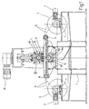
- the machine shown in Figure 1 and Figure 2 has a foundation 1, on which in the middle of a rolling stand 2 is constructed, in front of which and behind which in each case a receiving device 3 and 4 for a reel 5 and 6 attached is, which by a trained as an electric servomotor drive motor 7, 8 is drivable.
- a work roll 12 In side mounting parts 9 of the rolling stand is a work roll 12, below simply referred to as a roller, stored, which together with one underneath arranged flat plate 67 limits a nip 13. Above the Roller 12 and below plate 67 are each a support roller 14 and 15 in FIG Built-in parts 10 and 10a installed, which is larger in diameter than the Roller 12.
- the built-in parts 9, 9a of the work roll 12 are each in a cutout the built-in parts 10, 10 a of the support rollers 14, 15 are arranged.
- a metal strip 16 to be processed passes from the reel 5 via an overflow roller 17 into the nip 13, passes through it and passes via a further overflow roller 18 on the second reel 6, which in the rolling stand 2 machined metal band 16 wound. Between the nip 13 and the second overrun roller 18 is still a device 19 for the suction of Rolling oil provided in which the metal strip 16 is cleaned from the rolling oil becomes.
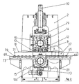
- the structure of the roll stand 2 is shown in more detail in Figures 3 and 4. It follows that the roller 12, whose diameter is only about 1/3 the diameter of the back-up rolls 14 and 15 is with their roll necks 20 and 21 are mounted in Rollenzapfenlagern 22, which formed as a roller bearing are. A roll neck 21 of the roll 12 is over its roll neck bearing 22 extended and formed as part of a gimbal 23, which allows the drive of the roller 12 by means of a propeller shaft 24. A roller 12 via the propeller shaft 24 synchronously driving electric motor 41 is shown in FIG. He drives the roller 12 and the lower support roller 15th via a branching gear 48. But it is also possible, the roller 12 and the backup roller 15 by two separate motors to drive.
- the support rollers 14 and 15 have roll necks 25, which in as a roller bearing trained roll neck bearing 26 of the side mounting parts 10 and 10 a stored are.
- the roll pins 25 are extended beyond the roll neck bearings 26 and stuck in cups 27, of which the cups of the lower Support roller 14 are braced with the foundation 1, while the bearing shells 27 of the upper support roller 15 clamped with a traverse arranged above 28 are.
- the clamping takes place in each case with one of the bearing shell 27th outgoing threaded rod 29, on which a set of disc springs 30 arranged is, which is tensioned by a nut 31. That's just above the crossbar 28, provided on the foundation 1 but in the same way.
- the plate 67 is supported not only by the lower support roller 15, but additionally through two squares of ball bearings 65, one of which is a field on the inlet side of the roll gap 13 and a field on the outlet side of the roll gap 13 is arranged.
- the ball bearings each consist of a pot 69, which is firmly closed by a convex lid 70.
- the lid 70 has a circular centered opening through which a below the lid arranged Ball 71, whose diameter is greater than the diameter of the center Hole, with a part of its spherical surface passes through.
- the ball 71 is replaced by a arranged in the pot 69 spring 72 against the crowned lid 70 pressed.
- the ball 71 is between the edge of the center Opening of the lid 70 and the spring 72 resiliently and otherwise freely movable stored.
- the ball bearings 65 are arranged in the two fields so that their Balls lie with their top in a common plane, in which they the the bottom of the plate 67 springy and smooth, that is, low-friction support.
- the ball bearings are arranged in brackets 66, which in height are adjustably mounted on the rolling stand 2. The height of the ball bearings 65 is adjusted so that the plate 67 during rolling, when against the lower support roller 15 is pressed, the balls 71 slightly from the edge of the central opening in the lid 70 presses down.
- the lower support roller 15 is by means of an adjusting device operating with wedges 73, which between the two roll stand window beds and the two lower roller bearing bodies of the lower support roller 15 is indicated in adjustable in vertical direction.
- the plate 67 in the vertical direction adjustable is indicated in adjustable.
- the plate 67 At the bottom of the plate 67 are interposed with the interposition of disc springs 84th attached to each other two parallel racks 82 which extend in the direction of Double arrow ( Figure 3) extend, that is the rolling direction.
- the racks 82 mesh with two sprockets 83, which laterally on the lower support roller 15th are fastened, in particular by shrinking onto the support roller 15.
- the plate 67 can be driven very accurately by the lower support roller 15 be, which in turn is driven by the electric motor 41 (FIG 2).
- the plate springs 84 compensate for a flattening of the support roller 15, which can be caused by the rolling forces.
- the plate 67 does not have its own drive but is replaced by the synchronous Driving the roller 12, the metal strip 16 and the lower support roller 15 taken by a friction lock. If the plate 67 between two Walz suitsen be retrieved, this is done by driving the lower Support roller 15 in the corresponding direction, with the required frictional engagement between the support roller 15 and the plate 67 by the weight of Plate 67 is effected. Should the dead weight for a reliable friction closure not sufficient, the plate 67 can additionally against the support roller 15th be pressed by rollers, not shown by means of pressure cylinders be pressed on the top of the plate 67.
- the required preload of the roll stand 2 is using two spindles 32 and 33 generated, which from above on the traverse 28 and on the bearing shells Press 27 and each by its own, on top of the mill stand 2 arranged, electric motor 34 (see Figure 1) are driven.
- both electric motors 34 have a trained as a pinion driving Shaft 49, the teeth of each mesh with a gear 50.
- the two Gears 50 are rotatably on the one spindle 32 and on the other spindle 33 attached.
- the appropriate preload of the rolling stand is empirical the elongation of the rolling stand determined in each application and so adjusted so that the strain is compensated. After this default works the machine according to the invention as follows:
- the metal strip 16 to be processed is unrolled from the first reel 5, through passed through the nip 13, pulled to the second reel 6 and on this attached.
- the plate 67 has a flat top.
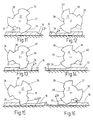
- the roller 12 has a lateral surface (FIG 5) with a profiled peripheral portion 35, which in the circumferential direction the roller 12 measured has a length L1, and a cylindrical peripheral portion 36, which measured in the circumferential direction of the roller 12 has a length L2 has, both separated by two recesses 37 and 38.
- the cylindrical Peripheral portion 36 of the lateral surface has the greatest distance from the Axle of the roller 12, the recesses 37 and 38 have the smallest distance from the axis of the roller 12.
- the profiled peripheral portion 35 of the lateral surface has a contour whose course is aligned in the circumferential direction on the Longitudinal course of the thickness of a workpiece, z. B. a nib, from the Metal band 16 is finally to be produced.
- the processing of the metal strip 16 begins with that in between the two reels 5 and 6 strained metal band of the cylindrical peripheral portion 36 of the roller 12 punctures, gently at standstill of the metal strip 16 and at non-rotating roller 12, at best, at a slower, to a low Peripheral speed of the cylindrical peripheral portion 36 adapted Feed rate of the metal strip 16.
- This puncture phase is shown in FIG 5, but not to scale, but with exaggerated dickem Metal band 16.
- Figures 6 to 16 are also the Stichabsure of the metal strip exaggerated by the rolling process, to make the rolling process clearer.
- the cylindrical peripheral portion 36 rolls on the metal strip 16 and reduces its thickness typical of 0.66 mm to 0.60 mm with simultaneous leveling of Dikke.
- the end of the leveling step is shown in FIG.
- the metal band 16 now comes out of engagement of the cylindrical peripheral portion 36 of the roller 12, which continues to rotate a little bit until the cutout 37 the metal band 16 faces.
- the metal strip 16 is now by Umsteuem the two formed as servomotors drive motors 7 and 8, namely by a length greater than L1 but less than L2; L2 is the length, on which the metal band 16 has been leveled.
- the servomotors provide 8 and 9 for a uniform as possible tensile stress in the metal strip 16th
- FIGS. 11 to 16 differs from the embodiment shown in Figures 5 to 10 in that the Top roller 12 not only with two peripheral portions, but with three peripheral portions 35, 36 and 40, which by recesses 37, 38 and 39 from each other are separated, acting on the metal strip 16 to be processed. That's it provided roll stand 2 has the same structure as shown in Figures 1 to 4, with the proviso that as roller 12 in the figures 11 to 16 shown roller 12 is used, wherein the profiling of the roller 12 exaggerated is shown strongly. Also in this example the leveling step is not mandatory.
- the peripheral portion 36 is cylindrical, whereas the two peripheral portions 35 and 40 have a non-cylindrical profile. As in the example of the figures 5-10, the cylindrical peripheral portion 36 has the largest one throughout Distance from the axis of the roller 12, which is advantageous when it comes goes, the cylindrical peripheral portion, which serves to leveling after Needs to be sharpened.
- FIG. 11 shows, analogously to FIG. 5, the insertion of the cylindrical peripheral section 36 of the roller 12 in the metal strip 16.
- Figure 12 shows analogous to the figure 6 the end of the leveling step.
- the roller 12 by means of the spindles 32nd and 33 down to the height of the nip 13 for the subsequent to set the first profiling rolling, the beginning of which is shown in FIG is.
- FIG. 13 corresponds to FIG. 7 and shows the insertion of the first non-cylindrical, profiled peripheral portion 35 of the roller 12.
- Figure 14 corresponds to Figure 8 and shows the end of the first profiling rolling step.
- the metal strip 16 passes again from the Engage out and in this phase while the cutout 39 the metal band 16, this is brought back one more time and by pressing the spindles 32 and 33 set the nip 13 for the second profiling roll step, its beginning with the piercing of the profiled peripheral portion 40 is shown in FIG.
- Figure 16 shows the end of the second roll forming step.
- the metal strip 16 is again free and can for leveling in subsequent band section are positioned, with simultaneous or subsequent Setting the height of the roll gap intended for leveling 13.
- the sequence of steps illustrated in FIGS. 11 to 16 is then repeated.
- Starting position e.g., 0 ° position
- Starting position e.g., 0 ° position
- This procedure is particularly suitable for the production of profiled sections in tapes where the desired stitch loss is not or only difficult or not with the desired accuracy in a single profiling roll step can be achieved.
- the invention can also be carried out with more than two profiling rolling steps become.
- the diameter of the roller 12 can be increased as needed.
- the invention is not only applicable to the production of starting material for Nibs, but also for the production of other strip-shaped materials, which in a sequence of regularly recurring sections about the entire width of the metal strip 16 is profiled, e.g. for the production of a strip-shaped starting material for the production of electrical conductor structures such as As contact springs or lead frames or for the production of grooved Ribbons with transverse to the longitudinal direction of the metal strip 16 parallel or not parallel grooves extending to the roll axis, with or without pockets or niches, which grooves are continuous from one to the other longitudinal edge of the metal strip extend and from which e.g. Commutator bars, electric Connector or other electrical contact parts can be punched out. Also by profiling stiffened sheet metal parts for the automotive industry can inexpensive and manufactured with high accuracy. Each with the help of optionally profiled rolls producible profile shape can by the inventive Procedures are formed.
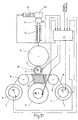
- FIG. 17 shows, in a schematic diagram, how the servomotors 7 and 8 the two reels 5 and 6, preferably also designed as servomotors Electric motors 41 and 42, for driving the roller 12 and the backup roller 15, and the two electric motors 34, which are preferably also is servomotors with downstream gear 34a and with which by means of the spindles 33 and 32, the roller 12 can be moved over a unitary electronic control unit 43 are linked together.
- a control unit 43 In order to can be predetermined as a function of a control unit 43 and preferably stored in digital form profile shape, which in the metal band 16 is to be rolled, by controlling the servomotors 7 and 8 of the feed controlled by the metal strip 16 during rolling and retrieval, matched to it the roller 12 and the backup roller 15 are rotated, stopped and optionally turned back and depending on the feed of the metal strip 16 and the shape entered into the control unit 43, the roller 12 by pressing the electric motors 34 are displaced.
- the current positions each returned by incremental encoders to the controller 43.
- These encoders are part of servomotors 7, 8, 41 and 42. Between the spindles 32 and 33 and the two servo motors 34 is each an incremental Encoder 44 shown separately by way of example.
- FIG. 17 shows a cylindrical roller 12, which has a radial, axis-parallel Incision 45 has to gain a reference for their angular position.
- the roller 12 has a non-cylindrical peripheral portion, such as shown in the previous examples, a shift of the roller 12 omitted during rolling; she would then only if necessary between take place the individual rolling steps.
- the curve after which the roller 12 is displaced can not only be software stored in the control unit. Basically, rather, a mechanical Curve control by means of a synchronous with the tape feed Cam possible.
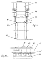
- FIG. 18 shows an embodiment modified with respect to FIGS. 1 to 4. It differs from the embodiment of Figures 1 to 4 in that instead of reels 5 and 6 forceps feed devices 52nd and 53 are provided. This embodiment is particularly suitable for shorter or thicker metal bands 16, which are not so easily wound can.
- the forceps feeders 52 and 53 have a carriage 56, 57 which by means of a servomotor 54, 55 in the horizontal direction of the nip 13 and can be removed from it.
- a dovetailed spring 58 is provided, which engages in a mating dovetail groove 59, 60, which is formed on a lug portion 61, 62 of the roll stand 2.
- the engagement of groove 59, 60 and spring 58 is an accurate horizontal guide the carriage 56, 57 reached.
- Other types of leadership are possible.
- On Each carriage 56, 57 is a rigidly attached to the carriage lower Bake 63 and an upper jaw 64, whose distance from the lower jaw variable is, preferably by means of a pressure medium cylinder.
- the Pliers feed devices 52 and 53 can individually but also together be operated and moved together. In the second case it is possible, both when rolling and when retrieving in between the two gripper feed devices 52 and 53 clamped portion of the Metal band 16 to maintain a defined tensile stress.
- the two forceps feed devices 52 and 53 are, as shown in FIG. 18, arranged adjacent to the nip 13. At the outlet side of the roll gap 13 is following in the rolling direction on the forceps feed device 53 arranged the means 19 for sucking off rolling oil, to which a Thickness gauge 51 connects, which the thickness of the rolled metal strip 16th detected and reported with a probe or non-contact, so that in case of deviations can be controlled or regulated by the desired thickness, to change the height of the nip 13 in a suitable manner.
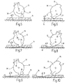
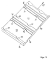
- Figure 19 shows a producible by the invention metal strip 16, which under Forming transverse grooves 74 in the bottom of the metal strip 16 and transverse grooves 75 and 76 in the top of the metal strip 16 has been profiled on both sides by the method according to the invention, wherein in a first pass, the grooves 74 in the bottom and in a second pass, after turning the metal strip, the grooves 75 and 76th were formed in the top of the metal strip 16.
- the order of the process steps is not mandatory.
- the grooves 74 narrower than the overlying grooves 75, which are in the top of the Metal band 16 with the narrower grooves 76 alternate.
- a special feature is that the wider grooves 75 continue into rectangular niches 77, their depth measured in the longitudinal direction 79 of the belt 16 relative is small, so that the displacement of the material from the niches manageable is.
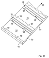
- inventively producible metal strip differs from the metal strip shown in Figure 19 in that instead of rectangular niches 77 arcuate niches 78 has been generated are.
- the invention not only allows the production of metal strips with grooves, which expand into rectangular or arcuate niches, as in the figures 19 and 20, but also allows, in a metal band 16 in a row and / or side by side depressions 80 to form, which is a closed Outline, z. B. triangular, rectangular or circular bordered are as shown in Figure 21. Other outlines are possible.
- the recesses 80 are peripheral walls limited, which is perpendicular or nearly perpendicular to the plate 67 run. The peripheral walls of the recesses 80 but can also be inclined to the plate 67, in such a way that the depressions from their bottom starting to expand towards the top of the metal strip 16 out.
- Such recesses 80 can be formed by the metal strip 16 is moved through the gap between the work roll 12 and a plate 67, which on its upper side to the recesses 80 complementary humps 81st has, which are shown schematically in Figures 3a and 4a.
Landscapes
- Engineering & Computer Science (AREA)
- Mechanical Engineering (AREA)
- Metal Rolling (AREA)
Claims (74)
- Procédé pour la fabrication d'un produit de départ métallique en forme de ruban qui est soumis à un profilage unilatéral ou bilatéral dans des tronçons successifs par laminage d'un ruban métallique en franchissant un ou plusieurs pas de laminage, en passant par les pas opératoires suivants consistant à :(a) tendre le ruban métallique (16) ;(b) positionner le ruban métallique (16) dans une zone de serrage (13) qui est délimitée par un cylindre (12) et par une plaque (67) mobile par rapport au cylindre (12) ;(c) positionner la plaque (67) par rapport au cylindre (12) ;
les pas (b) et (c) pouvant être franchis de manière successive ou de manière simultanée ou en présentant un chevauchement réciproque dans le temps ou encore dans l'ordre inverse, le pas (c) pouvant également précéder le pas (a) ;(d) pratiquer une saignée dans le ruban métallique (16) avec le cylindre (12) en rétrécissant l'écart existant entre la surface latérale () du cylindre (12) et le ruban métallique (16), le ruban métallique (16) étant laissé à l'état de repos ou en tout cas étant mis en mouvement de manière à ce point lente et le cylindre (12) n'étant pas mis en rotation ou en tout cas étant soumis à une rotation à ce point lente que le ruban métallique (16) reste soumis à une contrainte de traction dans la zone de serrage (13), au moins dans la phase naissante de la saignée ;(e) laminer un tronçon du ruban métallique (16) dans la zone de serrage (13), le cylindre (12) étant pour ce faire mis en rotation, et la plaque (67) étant soumise à un mouvement ou à un entraínement rectiligne de manière synchrone à ladite rotation ;(f) libérer le ruban métallique (16) par ouverture de la zone de serrage (13) ;
les pas (b) et (f) étant répétés pour chaque tronçon du ruban métallique (16), qui doit être profilé. - Procédé selon la revendication 1, caractérisé en ce que le ruban métallique (16) n'est soumis qu'à un profilage unilatéral.
- Procédé selon la revendication 1, caractérisé en ce que le ruban métallique (16) n'est d'abord soumis qu'à un profilage unilatéral avant d'être retourné de telle sorte que son côté profilé est orienté vers la plaque (67), et en ce que le ruban métallique (16) est ensuite soumis à un profilage sur son autre côté.
- Procédé selon la revendication 3, caractérisé en ce qu'après le profilage du premier côté du ruban métallique (16), on procède à un échange entre la plaque (67) et une plaque qui présente un profil qui correspond déjà de manière complémentaire au profil réalisé par laminage dans le ruban métallique (16).
- Procédé selon l'une quelconque des revendications précédentes, caractérisé en ce qu'on utilise une plaque plane (67) lorsque le ruban métallique (16) n'est soumis qu'à un profilage unilatéral ou n'est soumis dans un premier temps qu'à un profilage unilatéral.
- Procédé selon l'une quelconque des revendications précédentes, caractérisé en ce qu'on réalise par façonnement, dans le ruban métallique (16), des renfoncements (80) du type à bordure périphérique fermée ; à cet effet, on utilise, à titre de plaque (57), une plaque qui présente des protubérances (81) complémentaires aux renfoncements (80).
- Procédé selon la revendication 6, caractérisé en ce que, de manière simultanée au façonnement des renfoncements (80), par l'action du cylindre (12), qui fait face à la plaque (67), sur le ruban métallique (16), on obtient globalement une réduction modérée de l'épaisseur du ruban métallique (16).
- Procédé selon la revendication 7, caractérisé en ce que la réduction modérée de l'épaisseur du ruban métallique (16) représente environ 10 % de son épaisseur préalable.
- Procédé selon la revendication 6, 7 ou 8, caractérisé en ce que des renfoncements (80) sont réalisés en passant par plusieurs pas et la pente de la bordure périphérique des renfoncements (80) augmente pas à pas.
- Procédé selon l'une quelconque des revendications précédentes, caractérisé en ce que la contrainte de traction s'exerçant dans le ruban métallique (16) est maintenue constante lors de la saignée et lors du laminage.
- Procédé selon l'une quelconque des revendications précédentes, caractérisé en ce que, lors de la mise en oeuvre de plusieurs pas de laminage pour le profilage du ruban métallique (16) dans les tronçons prévus à cet effet, on répète les pas opératoires (a) à (e) et, pour ce faire, après l'ouverture de la zone de serrage (13), le ruban métallique (16) est repris et, à l'intervention du même cylindre (12) dans la zone de serrage (13), est soumis une nouvelle fois à un laminage dans le tronçon qui a été repris.
- Procédé selon l'une quelconque des revendications précédentes, caractérisé en ce que le ruban métallique (16) n'est pas soumis à un laminage au cours de la reprise.
- Procédé selon l'une quelconque des revendications 1 à 11, caractérisé en ce que le ruban métallique (16) est également soumis à un laminage au cours de la reprise.
- Procédé selon l'une quelconque des revendications précédentes, caractérisé en ce que la plaque (67) est montée en flottement.
- Procédé selon l'une quelconque des revendications précédentes, caractérisé en ce que le cylindre (12) délimite la zone de serrage (13) à partir du haut et en ce que la plaque (67) est disposée à l'horizontale et est soutenue par un cylindre de support (15).
- Procédé selon l'une quelconque des revendications précédentes, caractérisé en ce que la plaque (67) est soutenue des deux côtés de la zone de serrage (13).
- Procédé selon la revendication 15 ou 16, caractérisé en ce que la plaque (67) est soutenue des deux côtés de la zone de serrage (13) par des corps cylindriques ( ).
- Procédé selon l'une quelconque des revendications précédentes, caractérisé en ce que la surface ( ) de la plaque (67), orientée vers le cylindre (12) est de configuration plane.
- Procédé selon l'une quelconque des revendications précédentes, caractérisé en ce que la plaque (67) est mise en mouvement lors du laminage de par son entraínement via l'actionnement du cylindre (12) et/ou du ruban métallique (16).
- Procédé selon l'une quelconque des revendications 13 à 17, caractérisé en ce que la plaque (67) est mise en mouvement de par son entraínement par son cylindre de support (15) via l'actionnement de ce dernier..
- Procédé selon l'une quelconque des revendications précédentes, caractérisé en ce que le ruban métallique (16) est soumis à une reprise sur une longueur qui est inférieure à la périphérie du cylindre (12).
- Procédé selon l'une quelconque des revendications précédentes, caractérisé en ce que le ruban métallique (16) est soumis en même temps à un nivellement par le laminage.
- Procédé selon l'une quelconque des revendications précédentes, caractérisé en ce qu'à l'aide du cylindre (12), dans les tronçons du ruban métallique (16), on réalise un profil par laminage qui s'étend sur toute la largeur du ruban métallique (16), si bien que le ruban métallique (16) présente une épaisseur qui se modifie sur sa longueur.
- Procédé selon la revendication 23, caractérisé en ce qu'on réalise par laminage, dans le ruban métallique (16), un profil qui se répète de manière périodique.
- Procédé selon l'une quelconque des revendications précédentes, caractérisé en ce que le cylindre (12), la plaque (67) et le ruban métallique (16) sont soumis à une accélération et à un freinage synchrones et dans une mesure identique lors du franchissement des pas de laminage.
- Procédé selon l'une quelconque des revendications précédentes, caractérisé en ce que, pour la fabrication d'une matière de départ en forme de ruban possédant un profil sélectionné qui se répète dans des tronçons successifs de la matière de départ, le ruban métallique (16), avec ses tronçons qui doivent être soumis à un profilage, est guidé de manière répétée, en franchissant des pas de longueurs prédéfinies, à travers la zone de serrage (13) et la hauteur de la zone de serrage (13), jusqu'à ce que l'on atteigne, dans les tronçons concernés du ruban métallique (16), la profondeur désirée du profil sélectionné de la matière de départ, diminue pas à pas.
- Procédé selon l'une quelconque des revendications précédentes en liaison avec la revendication 14, caractérisé en ce que le ruban métallique (16), dans un premier pas de laminage, est seulement soumis à une réduction de son épaisseur, sans être encore profilé.
- Procédé selon la revendication 27, caractérisé en ce que le ruban métallique (16) est soumis à un nivellement dans le premier pas de laminage.
- Procédé selon la revendication 27 ou 28, caractérisé en ce que font suite au pas de réduction par laminage, un ou plusieurs pas de profilage par laminage dans une seule et même zone de serrage (13).
- Procédé selon la revendication 27, 28 ou 29, caractérisé en ce que la longueur (L2) du pas de réduction par laminage, au cours duquel le ruban métallique est le cas échéant également soumis à un nivellement - en prenant en compte l'étirage du tronçon soumis à une réduction, qui doit encore avoir lieu au cours du profilage ultérieur - , est supérieure à la longueur (L1) du pas de profilage par laminage qui suit directement.
- Procédé selon l'une quelconque des revendications 27 à 30, caractérisé en ce que le ruban métallique (16) est soumis à une reprise, après le pas de réduction par laminage, sur une longueur qui est inférieure à la longueur (L2) de du pas de réduction par laminage et qui est supérieure à la longueur (L1) du pas de profilage par laminage qui suit directement, dans le même tronçon du ruban métallique (16).
- Procédé selon l'une quelconque des revendications précédentes en liaison avec la revendication 14, caractérisé par l'utilisation d'une cage de laminoir (2) dans laquelle le cylindre (12) possède, sur sa surface latérale, une section profilée (35, 40) dont le contour délimite, avec la plaque (67), la zone de serrage (13).
- Procédé selon l'une quelconque des revendications précédentes, caractérisé en ce que le cylindre (12) possède une surface latérale cylindrique qui est de préférence subdivisée en segments de diamètre égal ou inégal.
- Procédé selon l'une quelconque des revendications 1 à 32 en liaison avec la revendication 19, caractérisé en ce que, avant la réalisation d'un profil par laminage, on soumet le ruban métallique (16), dans la zone de serrage (13) entre le cylindre (12) et la plaque (67), en franchissant d'abord des pas possédant une longueur (L2) qui n'est pas inférieure à la longueur (L1) du premier pas de profilage par laminage, à un nivellement à l'aide d'une réduction modérée de son épaisseur ; on le soumet ensuite à une reprise en franchissant un pas dont la longueur correspond au minimum à la longueur (L1) du premier pas de profilage par laminage et au maximum à la deuxième longueur (L2), avant de réaliser le profil par laminage dans le tronçon du ruban métallique (16), qui a été soumis à une reprise, et en ce que le cylindre (12), pour le nivellement du ruban métallique (16), possède, sur sa surface latérale, une section périphérique cylindrique (36) qui est séparée de la section périphérique profilée ou des sections périphériques profilées (35, 40), qui ne présentent pas un contour cylindrique.
- Procédé selon l'une quelconque des revendications précédentes, caractérisé en ce que, au cours du laminage du ruban métallique (16), le cylindre (12) de la cage de laminoir (2) est soumis à un déplacement pour la modification de la hauteur de la zone de serrage (13).
- Procédé selon la revendication 35, caractérisé en ce que le cylindre (12) est soumis à un déplacement via une servocommande (32, 34, 44).
- Procédé selon la revendication 36, caractérisé en ce qu'on utilise, pour la servocommande, un ou deux moteurs électriques (34) ou bien un ou deux cylindres hydrauliques à petite course.
- Procédé selon l'une quelconque des revendications 35 à 37, caractérisé en ce que le déplacement du cylindre (12) a lieu à l'aide d'un entraínement commandé par programme (32, 33, 34, 44), le profil à générer dans le pas de laminage respectif étant mémorisé dans un appareil de commande programmable (43) sous la forme d'une courbe de commande pour l'entraínement (32, 33, 34, 44) mettant en oeuvre le déplacement du cylindre (12).
- Procédé selon l'une quelconque des revendications 35 à 38, caractérisé en ce que le cylindre (12) possède une encoche (45) parallèle à l'axe.
- Procédé selon l'une quelconque des revendications précédentes, caractérisé en ce que le cylindre (12) est soumis à un entraínement pas à pas et de manière synchrone avec l'avance du ruban métallique (16).
- Procédé selon l'une quelconque des revendications précédentes en liaison avec la revendication 18, caractérisé en ce qu'on prévoit, dans la surface latérale du cylindre (12), entre les sections périphériques (35, 36, 40) actives lors du laminage, un évidement (37, 38, 39) qui s'étend en formant un angle périphérique tel que la section périphérique, respectivement suivante (35, 36, 40) active lors du laminage, n'entre pas en contact avec le ruban métallique (16) avant que la section périphérique précédemment active lors du laminage ne s'écarte du ruban métallique (16).
- Procédé selon l'une quelconque des revendications précédentes, caractérisé en ce que le ruban métallique (16) qui doit être soumis à un laminage est déroulé d'un premier dévidoir (5) et le ruban métallique (16) qui a été soumis à un laminage est enroulé sur un deuxième dévidoir (6), et en ce que la vitesse de rotation du cylindre (12) et la vitesse périphérique des dévidoirs (5, 6) sont adaptées l'une par rapport à l'autre, en particulier dans la phase de la saignée du cylindre (12) dans le ruban métallique (16).
- Procédé selon l'une quelconque des revendications précédentes, caractérisé en ce que la saignée du cylindre (12) a lieu dans le cadre d'une diminution de la vitesse de rotation du cylindre (12) et par conséquent dans le cadre d'une diminution de la vitesse d'avance du ruban métallique (16) et en ce que les mouvements sont ensuite soumis à une accélération.
- Procédé selon l'une quelconque des revendications 1 à 40, caractérisé en ce que le ruban métallique (16) est soumis à une reprise avec une première pince (52).
- Procédé selon la revendication 44, caractérisé en ce que le ruban métallique (16) est également soumis à une avance, avec la première pince (52), à des fins de laminage.
- Procédé selon la revendication 43 ou 44, caractérisé en ce que le ruban métallique (16), lors du laminage, est tiré avec une deuxième pince (53) qui agit sur un tronçon du ruban métallique (16), qui quitte la zone de serrage (13).
- Procédé selon l'une quelconque des revendications précédentes, caractérisé en ce que, au cours du laminage et également au cours de la reprise du ruban métallique (16), on maintient de manière constante dans ce dernier une contrainte de traction.
- Procédé selon l'une quelconque des revendications précédentes, caractérisé en ce que, au cours de la saignée du cylindre (12) dans le ruban métallique (16), on maintient de manière constante dans ce dernier une contrainte de traction.
- Procédé selon l'une quelconque des revendications précédentes, caractérisé en ce qu'on sélectionne une largeur du ruban métallique (16) telle que l'on peut découper, à partir d'objets qui doivent être découpés, conformément aux dispositions prévues, à partir de la matière de départ formée par laminage, deux objets ou plus de deux objets disposés les uns à côté des autres.
- Utilisation du procédé selon l'une quelconque des revendications précédentes sur des rubans constitués d'une matière synthétique et sur des rubans constitués d'un matériau composite à base d'une matière synthétique ou comprenant une matière synthétique à titre de constituant essentiel.
- Dispositif pour la fabrication d'une matière de départ en forme de ruban, en particulier en métal, par laminage d'un ruban (16), en particulier conformément au procédé selon la revendication 1 ou selon la revendication 50,
comprenant une cage de laminoir (2) dans laquelle un cylindre (12) délimite une zone de serrage (13),
et un dispositif de reprise (5, 52) pour le ruban (16), disposé du côté entrée de la zone de serrage (13) ;
caractérisé en ce qu'on prévoit, pour le dispositif de reprise (5, 52), un moteur d'entraínement (7, 54) qui permet de réaliser une reprise du ruban (16) en franchissant des pas de longueur prédéfinie, en particulier un servomoteur, et en ce que la zone de serrage (13) est délimitée en outre par une plaque (67) orientée vers le cylindre (12), apte à un déplacement rectiligne, qui peut être entraínée dans la zone de serrage (13) de manière synchrone avec le cylindre (12) et/ou avec le ruban (16) dans la direction de mouvement prédéfinie du ruban (16) et qui peut également être soumise à un entraínement et à une reprise, indépendamment du ruban (16). - Dispositif selon la revendication 51, caractérisé en ce que la plaque (67) est disposée en dessous du cylindre (12).
- Dispositif selon la revendication 51 ou 52, caractérisé en ce que la hauteur de la zone de serrage (13) est variable.
- Dispositif selon la revendication 51 pour la fabrication d'une matière de départ en forme de ruban, possédant un profil sélectionné qui se répète dans des tronçons successifs de la matière de départ,
caractérisé en ce que le cylindre (12) et/ou la plaque (67) peuvent être soumis, au cours du laminage, de manière contrôlée, à un déplacement ascendant et descendant dans la cage de laminoir, et en fait en suivant une voie déterminée par le profil sélectionné, en fonction de l'avance du ruban (16). - Dispositif selon l'une quelconque des revendications 51 à 54, caractérisé en ce que le cylindre (12) possède une surface latérale cylindrique.
- Dispositif selon la revendication 53 pour la fabrication d'une matière de départ en forme de ruban, possédant un profil qui se répète dans des tronçons successifs de la matière de départ,
caractérisé en ce que le cylindre (12) possède, sur sa surface latérale, deux sections ou plus de deux sections périphériques séparées (35, 36, 40), qui se succèdent dans la direction périphérique, qui ne manifestent pas toutes une concordance en ce qui concerne leur contour. - Dispositif selon l'une quelconque des revendications 51 à 56, dans lequel le dispositif de reprise pour le ruban (16) est un premier dévidoir (5).
- Dispositif selon l'une quelconque des revendications 51 à 56, dans lequel le dispositif de reprise pour le ruban (16) est un premier dispositif d'avance (52) sous la forme d'une pince.
- Dispositif selon l'une quelconque des revendications 51 à 58, dans lequel on prévoit, du côté sortie de la zone de serrage (13), un dispositif de traction (6, 53) pour la matière de départ en forme de ruban.
- Dispositif selon la revendication 59, dans lequel le dispositif de traction est un deuxième dévidoir (6) pour l'enroulement de la matière de départ en forme de ruban.
- Dispositif selon la revendication 59, dans lequel le dispositif de traction est un deuxième dispositif d'avance (53) sous la forme d'une pince.
- Dispositif selon la revendication 56, dans lequel le cylindre (12) possède une section périphérique cylindrique (36).
- Dispositif selon l'une quelconque des revendications 51 à 62, dans lequel la cage de laminoir (2) est réalisé sous la forme d'une laminoir de nivellement.
- Dispositif selon l'une quelconque des revendications 51 à 63, dans lequel le moteur d'entraínement (7, 52) pour le dispositif de reprise (5, 52) prévu du côté entrée de la zone de serrage (13), est un servomoteur électrique.
- Dispositif selon l'une quelconque des revendications 51 à 64, dans lequel le dispositif de traction (6, 53) prévu du côté sortie de la zone de serrage (13), est entraíné par un servomoteur électrique (8, 55).
- Dispositif selon l'une quelconque des revendications précédentes, caractérisé en ce qu'on attribue au dispositif de reprise (5, 52) et/ou au dispositif de traction (6, 53), un rouleau couplé à un encodeur incrémentiel, qui est mis en rotation par le ruban (16) défilant par-dessus.
- Dispositif selon l'une quelconque des revendications 51 à 66, dans lequel le cylindre (12) et la plaque (67) sont sollicités, sur leur côté se détournant de la zone de serrage (13), par respectivement un cylindre de support (14, 15), dont les tourillons de laminage (25) peuvent de préférence être mis en état de précontrainte dans leurs paliers de tourillons de laminage (26) à des fins de réduction de leur jeu de palier.
- Dispositif selon l'une quelconque des revendications 51 à 67, dans lequel le cylindre (12) est entraíné en discontinu, et en fait de telle sorte que, lors de l'avance du ruban, il est entraíné de manière synchrone avec le dispositif de traction (6, 53) prévu du côté sortie de la zone de serrage (13), tandis qu'il est en revanche mis à l'arrêt de manière temporaire et/ou positionné via une mise en rotation vers l'avant ou via une mise en rotation vers l'arrière lorsque le dispositif de reprise (5, 52) prévu du côté entrée de la zone de serrage (13) est entraíné dans le sens contraire pour le maintien de la traction du ruban et pour la reprise du ruban (16).
- Dispositif selon l'une quelconque des revendications 51 à 68, dans lequel la vitesse périphérique du cylindre (12) et la vitesse du dispositif de traction (6, 53), de préférence également celle du dispositif de reprise (5, 52), peuvent être réglées comme on le souhaite.
- Dispositif selon la revendication 53 ou 54, dans lequel, pour le déplacement du cylindre (12), on prévoit une ou plusieurs servocommandes (32, 33, 34, 44).
- Dispositif selon la revendication 70, dans lequel la servocommande (32, 33, 34, 44) comprend respectivement un moteur électrique (34) ou encore un ou deux cylindres hydrauliques à petite course.
- Dispositif selon la revendication 65, dans lequel on prévoit un appareil de commande électronique (43), dans lequel on mémorise sous la forme d'une courbe, le déplacement du cylindre (12) requis pour un profil prévu, et en fait de préférence sous forme numérique, et en ce que sont reliés, à cet appareil de commande (43), les servomoteurs (7, 8 ; 54, 55) du dispositif de reprise (5, 52) et du dispositif de traction (6, 53), un servomoteur (42) pour la mise en rotation du cylindre (12), et un ou plusieurs entraínements de déplacement (32, 33, 34) pour le cylindre (12), couplés à un encodeur incrémentiel (44), et en ce que, de préférence, on prévoit également un servomoteur pour le cylindre de support (15) de la plaque (67), éventuellement présent.
- Dispositif selon l'une quelconque des revendications 51 à 72, dans lequel, pour le laminage dans les deux directions, le sens de rotation du cylindre (12) et des dévidoirs (5, 6) peut être inversé.
- Dispositif selon l'une quelconque des revendications 51 à 73, dans lequel, le cylindre (12) possède une encoche (45) parallèle à l'axe.
Applications Claiming Priority (6)
| Application Number | Priority Date | Filing Date | Title |
|---|---|---|---|
| DE10056804 | 2000-11-11 | ||
| DE10056804A DE10056804A1 (de) | 2000-04-07 | 2000-11-11 | Verfahren zum Herstellen eines bandförmigen Vormaterials aus Metall, insbesondere eines solchen Vormaterials, welches in regelmäßig wiederkehrenden Abschnitten profiliert ist, und eine Vorrichtung dafür |
| DE10134285A DE10134285B8 (de) | 2000-11-11 | 2001-07-14 | Verfahren zum Herstellen eines bandförmigen Vormaterials, insbesondere aus Metall, welches in aufeinanderfolgenden Abschnitten profiliert ist, und eine Vorrichtung dafür |
| DE10134285 | 2001-07-14 | ||
| PCT/EP2001/012927 WO2002038305A1 (fr) | 2000-11-11 | 2001-11-08 | Procede de fabrication d'un produit de depart en forme de bande, notamment en metal, profile par sections successives, et dispositif y relatif |
| US10/435,310 US20040221635A1 (en) | 2000-11-11 | 2003-05-09 | Method for producing strip-shaped input stock, especially from metal, which is profiled in subsequent sections, and corresponding device |
Publications (2)
| Publication Number | Publication Date |
|---|---|
| EP1332011A1 EP1332011A1 (fr) | 2003-08-06 |
| EP1332011B1 true EP1332011B1 (fr) | 2005-06-15 |
Family
ID=33555873
Family Applications (1)
| Application Number | Title | Priority Date | Filing Date |
|---|---|---|---|
| EP01982471A Expired - Lifetime EP1332011B1 (fr) | 2000-11-11 | 2001-11-08 | Procede de fabrication d'un produit de depart en forme de bande, notamment en metal, profile par sections successives, et dispositif y relatif |
Country Status (4)
| Country | Link |
|---|---|
| US (1) | US20040221635A1 (fr) |
| EP (1) | EP1332011B1 (fr) |
| AU (1) | AU2002214044A1 (fr) |
| WO (1) | WO2002038305A1 (fr) |
Families Citing this family (12)
| Publication number | Priority date | Publication date | Assignee | Title |
|---|---|---|---|---|
| US7363791B2 (en) * | 2005-08-29 | 2008-04-29 | Gcg Holdings Ltd | Rotary stamping apparatus and method of forming sheet metal |
| CN101144763A (zh) * | 2007-09-17 | 2008-03-19 | 济南钢铁股份有限公司 | 一种热力机械模拟实验机用微型实验轧机 |
| JP6135390B2 (ja) * | 2013-08-09 | 2017-05-31 | 新日鐵住金株式会社 | 差厚鋼板の製造装置に用いられるワークロールまたはバックアップロールの加工方法 |
| KR102122217B1 (ko) * | 2015-03-16 | 2020-06-12 | 에스엠에스 그룹 게엠베하 | 금속 스트립을 제조하기 위한 방법 |
| KR102102550B1 (ko) * | 2015-11-30 | 2020-04-21 | 빅톨릭 컴패니 | 캠식 홈가공기 |
| US11898628B2 (en) | 2015-11-30 | 2024-02-13 | Victaulic Company | Cam grooving machine |
| US10525516B2 (en) | 2017-05-03 | 2020-01-07 | Victaulic Company | Cam grooving machine with cam stop surfaces |
| US10960450B2 (en) * | 2017-12-19 | 2021-03-30 | Victaulic Company | Pipe grooving device |
| CN109909301A (zh) * | 2019-03-08 | 2019-06-21 | 贺云坤 | 齿痕轧制机及使用齿痕轧制机制作内螺纹金属管的方法 |
| KR102890167B1 (ko) | 2019-08-21 | 2025-11-21 | 빅톨릭 컴패니 | 파이프 홈 가공 장치를 위한 파이프 수용 조립체 |
| CN110421209B (zh) * | 2019-08-23 | 2024-07-12 | 浙江祥博散热系统有限公司 | 一种电池冷板部件加工设备 |
| US11759839B2 (en) | 2020-09-24 | 2023-09-19 | Victaulic Company | Pipe grooving device |
Family Cites Families (11)
| Publication number | Priority date | Publication date | Assignee | Title |
|---|---|---|---|---|
| GB191423124A (en) * | 1914-11-26 | 1915-08-26 | Edward Williams | Improvements relating to Metal Rolling, Forging or Swaging Machines. |
| US2235241A (en) * | 1940-02-05 | 1941-03-18 | Atwood Vacuum Machine Co | Hinge and method of making members therefor |
| DE1175192B (de) * | 1959-11-26 | 1964-08-06 | Joachim Pfeiffer Dipl Ing | Verfahren und Vorrichtung zum Abstrecken von strangfoermigem Gut, z. B. Band |
| DE1577909A1 (de) * | 1966-02-15 | 1970-06-04 | Charles Ruetschi | Verfahren und Vorrichtung zur Herstellung von mit erhabenen Praegungen versehenen Baendern |
| US3415095A (en) * | 1967-02-08 | 1968-12-10 | Bringewald Process Corp | Process and apparatus for producing metal plates with integral stiffeners |
| JPS5542151A (en) * | 1978-09-19 | 1980-03-25 | Kobe Steel Ltd | Forging and rolling device |
| US4793169A (en) * | 1986-06-27 | 1988-12-27 | United Engineering, Inc. | Continuous backpass rolling mill |
| KR100230245B1 (ko) * | 1995-01-24 | 1999-11-15 | 윤종용 | 다층 광 기록 매체의 제조방법 및 그 장치 |
| DE19938966C1 (de) * | 1999-06-01 | 2000-10-19 | Carl Wezel Fa | Verfahren und Vorrichtung zum Herstellen eines bandförmigen Vormaterials aus Metall, insbesondere eines solchen Vormaterials welches in regelmäßig wiederkehrenden Abschnitten profiliert ist, und die Verwendung einer Vorrichtung dafür |
| ATE226491T1 (de) * | 1999-05-12 | 2002-11-15 | Hjb Rolling Mill Technology Gm | Verfahren zum herstellen eines bandförmigen vormaterials aus metall, insbesondere eines solchen vormaterials welches in regelmässig wiederkehrenden abschnitten profiliert ist, und die verwendung einer vorrichtung dafür |
| DE10056803B4 (de) * | 1999-08-17 | 2004-05-06 | Fa. Carl Wezel | Verfahren zum Herstellen eines bandförmigen Vormaterials aus Metall, insbesondere eines solchen Vormaterials, welches in regelmäßig wiederkehrenden Abschnitten profiliert ist, und eine Vorrichtung dafür |
-
2001
- 2001-11-08 WO PCT/EP2001/012927 patent/WO2002038305A1/fr not_active Ceased
- 2001-11-08 EP EP01982471A patent/EP1332011B1/fr not_active Expired - Lifetime
- 2001-11-08 AU AU2002214044A patent/AU2002214044A1/en not_active Abandoned
-
2003
- 2003-05-09 US US10/435,310 patent/US20040221635A1/en not_active Abandoned
Also Published As
| Publication number | Publication date |
|---|---|
| US20040221635A1 (en) | 2004-11-11 |
| WO2002038305A1 (fr) | 2002-05-16 |
| EP1332011A1 (fr) | 2003-08-06 |
| AU2002214044A1 (en) | 2002-05-21 |
Similar Documents
| Publication | Publication Date | Title |
|---|---|---|
| EP1332011B1 (fr) | Procede de fabrication d'un produit de depart en forme de bande, notamment en metal, profile par sections successives, et dispositif y relatif | |
| DE3529160A1 (de) | Formwalzvorrichtung | |
| EP1442808B1 (fr) | Matrice de laminage | |
| DE2856525A1 (de) | Verfahren und vorrichtung zur verarbeitung mit matrizenwalzen bzw. praegerollen | |
| DE60025702T2 (de) | Profilwalzen in einer revolverstanzpresse | |
| DE3622926C2 (de) | Kontinuierliches mehrstufiges Walzwerk | |
| DE2644900B2 (de) | Profiliermaschine | |
| DE10134285C2 (de) | Verfahren zum Herstellen eines bandförmigen Vormaterials, insbesondere aus Metall, welches in aufeinanderfolgenden Abschnitten profiliert ist, und eine Vorrichtung dafür | |
| DE69631272T2 (de) | Verfahren und Vorrichtung zur Herstellung von Draht | |
| DE102017116895B4 (de) | Verfahren und Vorrichtung zur Herstellung einer Verzahnung an einem zylindrischen Werkstück | |
| EP1183117B1 (fr) | Procede de fabrication d'un produit de depart metallique en forme de bande, en particulier d'un produit de depart profile a intervalles reguliers, et utilisation d'un dispositif permettant de mettre en oeuvre ledit procede | |
| DE2531591A1 (de) | Verfahren und einrichtung zum aendern des querschnittes von brammen | |
| CH653928A5 (de) | Verfahren zum biegen von profilblechen und vorrichtung zur durchfuehrung des verfahrens. | |
| DE10056803B4 (de) | Verfahren zum Herstellen eines bandförmigen Vormaterials aus Metall, insbesondere eines solchen Vormaterials, welches in regelmäßig wiederkehrenden Abschnitten profiliert ist, und eine Vorrichtung dafür | |
| DE19938966C1 (de) | Verfahren und Vorrichtung zum Herstellen eines bandförmigen Vormaterials aus Metall, insbesondere eines solchen Vormaterials welches in regelmäßig wiederkehrenden Abschnitten profiliert ist, und die Verwendung einer Vorrichtung dafür | |
| EP0501211A2 (fr) | Procédé pour actionner une presse à refouler | |
| EP2298468B1 (fr) | Presse annulaire dotée d'un moteur à couple | |
| DE10056804A1 (de) | Verfahren zum Herstellen eines bandförmigen Vormaterials aus Metall, insbesondere eines solchen Vormaterials, welches in regelmäßig wiederkehrenden Abschnitten profiliert ist, und eine Vorrichtung dafür | |
| DE10019175A1 (de) | Verfahren zum Herstellen eines bandförmigen Vormaterials aus Metall, insbesondere eines solchen Vormaterials welches in regelmäßig wiederkehrenden Abschnitten profiliert ist, und die Verwendung einer vorrichtung dafür | |
| AT510957B1 (de) | Verfahren und vorrichtung zum herstellen eines metallischen bandes | |
| DE7920030U1 (de) | Spanabhebende werkzeugmaschine | |
| DE53175C (de) | Verfahren und Vorrichtung zur Herstellung von gezahnten Schmiedestücken | |
| WO1997027957A1 (fr) | Machine de cintrage circulaire des toles | |
| DE19921720C1 (de) | Verfahren und Vorrichtung zum Herstellen eines abschnittsweise wiederkehrend profilierten bandförmigen Vormaterials für Schreibfedern | |
| DE3050654C2 (fr) |
Legal Events
| Date | Code | Title | Description |
|---|---|---|---|
| PUAI | Public reference made under article 153(3) epc to a published international application that has entered the european phase |
Free format text: ORIGINAL CODE: 0009012 |
|
| 17P | Request for examination filed |
Effective date: 20030522 |
|
| AK | Designated contracting states |
Designated state(s): AT BE CH CY DE DK ES FI FR GB GR IE IT LI LU MC NL PT SE TR |
|
| AX | Request for extension of the european patent |
Extension state: RO |
|
| RBV | Designated contracting states (corrected) |
Designated state(s): AT BE CH DE FR GB LI |
|
| RAP1 | Party data changed (applicant data changed or rights of an application transferred) |
Owner name: FIRMA CARL WEZEL |
|
| GRAP | Despatch of communication of intention to grant a patent |
Free format text: ORIGINAL CODE: EPIDOSNIGR1 |
|
| RBV | Designated contracting states (corrected) |
Designated state(s): DE FR GB |
|
| GRAS | Grant fee paid |
Free format text: ORIGINAL CODE: EPIDOSNIGR3 |
|
| GRAA | (expected) grant |
Free format text: ORIGINAL CODE: 0009210 |
|
| AK | Designated contracting states |
Kind code of ref document: B1 Designated state(s): DE FR GB |
|
| REG | Reference to a national code |
Ref country code: GB Ref legal event code: FG4D Free format text: NOT ENGLISH |
|
| REF | Corresponds to: |
Ref document number: 50106548 Country of ref document: DE Date of ref document: 20050721 Kind code of ref document: P |
|
| GBT | Gb: translation of ep patent filed (gb section 77(6)(a)/1977) |
Effective date: 20050921 |
|
| PLBE | No opposition filed within time limit |
Free format text: ORIGINAL CODE: 0009261 |
|
| STAA | Information on the status of an ep patent application or granted ep patent |
Free format text: STATUS: NO OPPOSITION FILED WITHIN TIME LIMIT |
|
| 26N | No opposition filed |
Effective date: 20060316 |
|
| EN | Fr: translation not filed | ||
| PG25 | Lapsed in a contracting state [announced via postgrant information from national office to epo] |
Ref country code: FR Free format text: LAPSE BECAUSE OF FAILURE TO SUBMIT A TRANSLATION OF THE DESCRIPTION OR TO PAY THE FEE WITHIN THE PRESCRIBED TIME-LIMIT Effective date: 20060811 |
|
| PGFP | Annual fee paid to national office [announced via postgrant information from national office to epo] |
Ref country code: GB Payment date: 20071009 Year of fee payment: 7 |
|
| PG25 | Lapsed in a contracting state [announced via postgrant information from national office to epo] |
Ref country code: FR Free format text: LAPSE BECAUSE OF FAILURE TO SUBMIT A TRANSLATION OF THE DESCRIPTION OR TO PAY THE FEE WITHIN THE PRESCRIBED TIME-LIMIT Effective date: 20050615 |
|
| GBPC | Gb: european patent ceased through non-payment of renewal fee |
Effective date: 20081108 |
|
| PG25 | Lapsed in a contracting state [announced via postgrant information from national office to epo] |
Ref country code: GB Free format text: LAPSE BECAUSE OF NON-PAYMENT OF DUE FEES Effective date: 20081108 |
|
| PGFP | Annual fee paid to national office [announced via postgrant information from national office to epo] |
Ref country code: DE Payment date: 20101110 Year of fee payment: 10 |
|
| REG | Reference to a national code |
Ref country code: DE Ref legal event code: R119 Ref document number: 50106548 Country of ref document: DE Effective date: 20120601 |
|
| PG25 | Lapsed in a contracting state [announced via postgrant information from national office to epo] |
Ref country code: DE Free format text: LAPSE BECAUSE OF NON-PAYMENT OF DUE FEES Effective date: 20120601 |