EP1331650B1 - Verfahren und Apparat zum Reduzieren der Zugkraft in Drähte während eines Seilherstellungsverfahrens - Google Patents
Verfahren und Apparat zum Reduzieren der Zugkraft in Drähte während eines Seilherstellungsverfahrens Download PDFInfo
- Publication number
- EP1331650B1 EP1331650B1 EP03075183A EP03075183A EP1331650B1 EP 1331650 B1 EP1331650 B1 EP 1331650B1 EP 03075183 A EP03075183 A EP 03075183A EP 03075183 A EP03075183 A EP 03075183A EP 1331650 B1 EP1331650 B1 EP 1331650B1
- Authority
- EP
- European Patent Office
- Prior art keywords
- wire
- roller
- speed
- wires
- winding
- Prior art date
- Legal status (The legal status is an assumption and is not a legal conclusion. Google has not performed a legal analysis and makes no representation as to the accuracy of the status listed.)
- Expired - Lifetime
Links
- 238000000034 method Methods 0.000 title claims abstract description 24
- 238000004519 manufacturing process Methods 0.000 title claims abstract description 7
- 238000004804 winding Methods 0.000 claims abstract description 30
- 239000003638 chemical reducing agent Substances 0.000 description 2
- 239000004020 conductor Substances 0.000 description 2
- 238000010586 diagram Methods 0.000 description 2
- 230000000694 effects Effects 0.000 description 2
- 230000002093 peripheral effect Effects 0.000 description 2
- 230000001105 regulatory effect Effects 0.000 description 2
- 230000002542 deteriorative effect Effects 0.000 description 1
- 238000012986 modification Methods 0.000 description 1
- 230000004048 modification Effects 0.000 description 1
- 238000003908 quality control method Methods 0.000 description 1
Images
Classifications
-
- H—ELECTRICITY
- H01—ELECTRIC ELEMENTS
- H01B—CABLES; CONDUCTORS; INSULATORS; SELECTION OF MATERIALS FOR THEIR CONDUCTIVE, INSULATING OR DIELECTRIC PROPERTIES
- H01B13/00—Apparatus or processes specially adapted for manufacturing conductors or cables
- H01B13/02—Stranding-up
- H01B13/0285—Pretreatment
Definitions
- the present invention relates to a method and an associated apparatus for reducing the tension of wires during a process for production of a strand using said wires.
- said strands are made from a wire or a plurality of wires wound onto a supply reel from which the wire(s) is/are unwound so as to be fed to the stranding machine which forms the bundles of wires, imparts one or more twists to them and winds the strand thus formed onto a take-up reel.
- the wire is however subject to slackening and/or tensioning and, in order to compensate for this, the supply reel is equipped with an arm for adjusting the unwinding speed; said arm has a roller onto which the wire is wound and is connected to means for adjusting the speed of rotation of the said reel.
- the wire is subject to a tension in the longitudinal direction which is permitted and regulated within certain limits, since it tends to equalize the behaviour of different wires wound onto the same reel and wires wound onto different reels.
- the technical problem which is posed, therefore, is that of providing a method and an apparatus which allows a reduction in the tension produced on the wire during winding thereof onto a reel, for example of a stranding machine.
- the present invention also relates to an apparatus for reducing the tension of wires during a process for forming a strand according to the characteristics of claim 8.
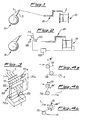
- a conventional plant for forming a strand 2 from at least one wire 1 comprises essentially a reel 10 for supplying the wire(s) 1, a device 20 for guiding the wire(s) entering a stranding machine, schematically shown together with the associated winding reel 30.
- the guiding device schematically shown is of the type able to impart a single twist to the wire, but, although not illustrated, the stranding machine may comprise means able to impart a double twist to the wires before they are wound onto the reel 30.
- the supply reel 10 is connected to an arm 11 for adjusting its speed of rotation, which arm is in turn connected to the wires being unwound.
- Fig. 2 shows the plant according to Fig. 1 equipped with an apparatus 100 for reducing the tension of the wires to which the wires 1 are subject during the process for forming and winding a strand 2, which apparatus is arranged in a position between the supply reel 10 and the point of entry into the stranding machine in the direction of feeding of the wires 1.
- the apparatus according to the invention will also be called a tension-reducing apparatus.
- the tension-reducing apparatus 100 is substantially formed by a first roller 111 which is motorized and by a second drive roller 112 which is idle, the wires 1 being made to pass between said rollers.
- the first motorized roller 111 is rotated by means of an associated controlled motor 111a which imparts a speed of rotation of the roller such as to produce a peripheral speed which is slightly greater than the driving speed of the stranding machine.
- the motor 111a is also connected to a speed control device 120, for example of the type called "encoder", onto which one of the wires 1 fed to the stranding machine is wound; said device is able to detect the speed of the roller and send corresponding signals to actuating means able to vary the speed of rotation of the motor 111a and therefore the corresponding roller 111.
- a speed control device 120 for example of the type called "encoder”
- the second idle roller 112 is mounted on an associated frame 112a which is movable translationwise parallel to the direction of feeding of the wires 1 so as to produce a relative position of the two rollers 111,112 such as to allow adjustment of the winding angle of the said wires 1 around the first motorized roller as illustrated in Figs. 4a to 4c where a winding angle of 90° is modified to a winding angle of about 180°.
- the second roller 112 is in turn motorized by means of a motor 111b which is also regulated by the encoder signal and imparts to the second roller 112 a speed of rotation which is substantially the same as that of the first roller 111 and therefore slightly greater than the speed of feeding of the wire.
- the tension-reducing effect is substantially determined by the winding angle on the first motorized (or active) roller - or by the sum of the winding angles on all the active rollers - it follows that, for the same reduction in tension on the wires 1, the motorization of the second roller 112 results in winding angles of the wires on the two active rollers which are smaller than those required in the case of an idle second roller, also allowing the mechanical design of the apparatus to be simplified.
- a method for reducing the longitudinal tension of wires 1 forming the components of a strand 2 to be wound onto a reel 30 of a stranding machine is also defined, said method envisaging the following steps:
- said pulling/pushing action is obtained by means of application of a sliding friction to the wire; said sliding friction being determined by the pulling/pushing action of a roller on which the wire is wound at a predefined winding angle depending on the characteristics of the wire and the strand to be formed.
- Said winding angle is normally between 60° and 300° and preferably between 90° and 240°.
- the roller which applies the pulling/pushing force to the wire is rotationally actuated so as to have a speed slightly greater than the speed of driving of the wire by the stranding machine.
- the peripheral speed of the roller is greater than the speed of driving of the wire by an amount ranging between 2% and 10% of the latter.
Landscapes
- Engineering & Computer Science (AREA)
- Manufacturing & Machinery (AREA)
- Ropes Or Cables (AREA)
- Wire Processing (AREA)
- Processes Specially Adapted For Manufacturing Cables (AREA)
Claims (16)
- Verfahren zur Herabsetzung der Spannung von Drähten (1) bei einem Herstellungsprozess eines Kabels (2) aus den genannten Drähten (1), das folgende Schritte umfasst:- Abwickeln mindestens eines Drahtes (1) von einer Versorgungsspule (10);- Zuführen des abgewickelten Drahtes (1), in einer Zuführungsrichtung, zu einer drahtziehenden Kabelwickelmaschine (30), und Aufwickeln desselben auf eine Aufnahmespule (31) bei einer vorbestimmten Wickelgeschwindigkeit ;dadurch gekennzeichnet, dass der mindestens eine Draht (1) einer Zug-und Schubwirkung in derselben Richtung wie dessen Zuführungsrichtung entlang dem Abschnitt des Bewegungspfades zwischen der Versorgungsspule und dem Eintrittspunkt in die Kabelwickelmaschine unterworfen wird, dadurch, dass die genannte Zug- und Schubwirkung durch einen Apparat aufgebracht wird, der eine erste Rolle (111) und eine zweite Rolle (112) umfasst, die um einen zur Zuführungsrichtung senkrechten Abstand voneinander getrennt sind, und mindestens eine der Rollen (111) motorisiert ist (111 a), wobei die genannte erste (111) und zweite Rolle (112) in einer Richtung parallel zur Zuführungsrichtung einander gegenüber verschiebbar sind und die Regelung eines Wicklungswinkels des mindestens einen Drahtes (1) erlauben.
- Verfahren gemäß Anspruch 1, dadurch gekennzeichnet dass die genannte Zug- und Schubwirkung durch Anwendung einer Gleitreibung an den Draht (1) erreicht wird.
- Verfahren gemäß Anspruch 2, dadurch gekennzeichnet dass die genannte Gleitreibung durch die Zug- und Schubwirkung eines Paares von motorisierten Rollen (111, 112) erreicht wird, auf die der Draht (1) mit einem vorbestimmten Wicklungswinkel gewickelt wird.
- Verfahren gemäß Anspruch 3, dadurch gekennzeichnet dass der genannte Wicklungswinkel zwischen 60° und 300° beträgt.
- Verfahren gemäß Anspruch 4, dadurch gekennzeichnet dass der genannte Wicklungswinkel vorzugsweise zwischen 90° und 240° beträgt.
- Verfahren gemäß Anspruch 1, dadurch gekennzeichnet dass die Rolle, die die Zug-und Schubwirkung auf den Draht (1) ausübt, drehbar derart betätigt wird, dass ihre Geschwindigkeit größer als die Antriebsgeschwindigkeit des Drahtes seitens der Kabelwickelmaschine (30) ist.
- Verfahren gemäß Anspruch 6, dadurch gekennzeichnet dass die Drehgeschwindigkeit der motorisierten Rolle (111, 111 a) um einen Betrag im Bereich zwischen 2% und 10% größer als die Antriebsgeschwindigkeit des Drahtes ist.
- Apparat zur Herabsetzung der Spannung der Drähte (1) bei einem Verfahren zur Formung eines auf eine Spule einer Kabelwickelmaschine (30) gewickelten Kabels (2) unter Verwendung von mindestens einem von einer Versorgungsspule (10, 11) entlang einer Zuführungsrichtung gespeisten Draht (1), dadurch gekennzeichnet, dass er Mittel (111, 112) umfasst, die imstande sind, dem genannten mindestens einem Draht (1) eine Zug- und Schubwirkung in derselben Richtung wie die der Zuführungsrichtung des genannten Drahtes (1) zu verleihen, wobei die genannten Zug- und Schubvorrichtungen (100) entlang dem Abschnitt des Bewegungspfads zwischen der Zuführungsrolle (10, 11) und der aufwickelnden Rolle (30) vor der Kabelwickelmaschine (30) liegen, die genannten Mittel (111, 112) mindestens eine erste Rolle (111) umfassen, die motorisiert und imstande ist, die genannte Zug- und Schubwirkung auszuüben, eine zweite Antriebsrolle (112) sich im Leerlauf befindet und die Drähte (1) um die genannten Rollen gewunden werden, und dass die genannten ersten (111) und zweiten (112) Rollen parallel zueinander stehen und dass die genannte zweite Rolle (112) der ersten Rolle (111) gegenüber beweglich verschiebbar ist, um eine Regelung des Wicklungswinkels des Drahtes (1) um die Rollen zu erlauben.
- Apparat gemäß Anspruch 8, dadurch gekennzeichnet, dass die genannten Schubvorrichtungen jeweils mindestens eine erste motorisierten Rolle (111) umfassen, die die genannte Zug- und Schubwirkung auszuüben vermag, und mindestens eine zweite motorisierte Rolle (112) umfassen, und die Drähte (1) um diese Rollen gewunden werden.
- Apparat gemäß Anspruch 8, dadurch gekennzeichnet, dass die genannte erste motorisierte Rolle (111) mit einer Drehgeschwindigkeit rotiert wird, die größer als die Wickelgeschwindigkeit der Spule (30) der Kabelwickelmaschine ist.
- Apparat gemäß Anspruch 10, dadurch gekennzeichnet, dass die Drehgeschwindigkeit der motorisierten Rolle (111) um einen Betrag größer als die Antriebsgeschwindigkeit des Drahtes (1) ist, der vorzugsweise in einem Bereich zwischen 2% und 10% des letzteren liegt.
- Apparat gemäß Anspruch 8, dadurch gekennzeichnet, dass die genannte erste motorisierte Rolle (111) mit einer größeren Drehgeschwindigkeit als die Wickelgeschwindigkeit der Kabelwickelmaschine rotiert wird, und die genannte zweite motorisierte Rolle (112) mit einer Geschwindigkeit rotiert wird, die im Wesentlichen dieselbe wie die der ersten Rolle ist.
- Apparat gemäß Anspruch 8, dadurch gekennzeichnet, dass er mindestens eine Vorrichtung (120) zum Kontrollieren der Drehgeschwindigkeit der motorisierten Rolle(n) umfasst, der (denen) einer der Drähte (1) der Kabelwickelmaschine (30) zugeführt wird.
- Apparat gemäß Anspruch 13, dadurch gekennzeichnet, dass die genannte Kontrollvorrichtung (120) imstande ist, die Geschwindigkeit der Rolle zu erfassen und entsprechende Signale an Betätigungsvorrichtungen auszusenden, um die Drehgeschwindigkeit des Motors (111a, 111b) zum Betätigen der motorisierten Rolle(n) zu ändern.
- Apparat gemäß Anspruch 8, dadurch gekennzeichnet, dass der Wicklungswinkel des Drahtes (1) um die motorisierte Rolle(n) zwischen 60° und 300° beträgt.
- Anlage für die Herstellung von Kabeln (2) aus Drähten (1), in der mindestens eine Wickelmaschine mit einer Wicklungsspule (30) und mindestens eine Spule (10, 11) für die Zuführung von mindestens einem Draht (1) vorgesehen werden, dadurch gekennzeichnet, dass sie einen Apparat für die Herabsetzung der Spannung des genannten mindestens einen Drahtes (1) gemäß Anspruch 8 umfasst.
Applications Claiming Priority (2)
| Application Number | Priority Date | Filing Date | Title |
|---|---|---|---|
| IT2002MI000120A ITMI20020120A1 (it) | 2002-01-24 | 2002-01-24 | Metodo e relativa apparecchiatura per il detensionamento di fili durante un processo di produzione di corde |
| ITMI20020120 | 2002-01-24 |
Publications (4)
| Publication Number | Publication Date |
|---|---|
| EP1331650A2 EP1331650A2 (de) | 2003-07-30 |
| EP1331650A3 EP1331650A3 (de) | 2003-12-03 |
| EP1331650B1 true EP1331650B1 (de) | 2010-07-28 |
| EP1331650B8 EP1331650B8 (de) | 2010-09-01 |
Family
ID=11448973
Family Applications (1)
| Application Number | Title | Priority Date | Filing Date |
|---|---|---|---|
| EP03075183A Expired - Lifetime EP1331650B8 (de) | 2002-01-24 | 2003-01-20 | Verfahren und Apparat zum Reduzieren der Zugkraft in Drähte während eines Seilherstellungsverfahrens |
Country Status (5)
| Country | Link |
|---|---|
| US (1) | US20030141400A1 (de) |
| EP (1) | EP1331650B8 (de) |
| AT (1) | ATE475973T1 (de) |
| DE (1) | DE60333509D1 (de) |
| IT (1) | ITMI20020120A1 (de) |
Families Citing this family (2)
| Publication number | Priority date | Publication date | Assignee | Title |
|---|---|---|---|---|
| CN105047319B (zh) * | 2015-08-25 | 2017-03-08 | 安吉腾飞电子有限公司 | 一种电线绞合收卷设备 |
| US10934142B2 (en) * | 2018-02-27 | 2021-03-02 | Hall Labs Llc | Motor-driven fairlead for assisting spooling or unspooling from a winch |
Family Cites Families (21)
| Publication number | Priority date | Publication date | Assignee | Title |
|---|---|---|---|---|
| US2127936A (en) * | 1935-11-29 | 1938-08-23 | Nat Standard Co | Wire winding apparatus |
| US2985393A (en) * | 1956-03-12 | 1961-05-23 | Glanzstoff Ag | Winding machine for the production of bobbins with predetermined thread tension overthe bobbin run |
| US3526368A (en) * | 1968-06-10 | 1970-09-01 | Deering Milliken Res Corp | Method and apparatus for winding thread |
| GB1235439A (en) * | 1969-06-18 | 1971-06-16 | Standard Telephones Cables Ltd | An arrangement for controlling the acceleration and tension of strip material being unwound from a spirally wound pad |
| US4212422A (en) * | 1978-09-18 | 1980-07-15 | Rca Corporation | Web position controller for web transport systems |
| JPS57144633A (en) * | 1981-03-05 | 1982-09-07 | Inoue Japax Res Inc | Wire electrode feeder |
| SE463667B (sv) * | 1987-11-03 | 1991-01-07 | Profor Ab | Avrullningsanordning foer banformigt material innefattande en bromsanordning styrd av banspaenningen |
| JPH01209139A (ja) * | 1988-02-18 | 1989-08-22 | Tokyo Kikai Seisakusho Ltd | 輪転機におけるガイドローラー装置 |
| JPH0227623A (ja) * | 1988-07-18 | 1990-01-30 | Sumitomo Wiring Syst Ltd | 圧縮導体の製造装置ならびに製造方法 |
| US4958111A (en) * | 1989-09-08 | 1990-09-18 | Gago Noel J | Tension and web guiding system |
| JPH0629112B2 (ja) * | 1990-10-08 | 1994-04-20 | 株式会社東京機械製作所 | アングルバー装置 |
| JP2909294B2 (ja) * | 1992-03-16 | 1999-06-23 | 日東グラスファイバー工業株式会社 | ガラスヤーンの製造方法 |
| DE69312899T2 (de) * | 1992-12-25 | 1997-12-11 | Ishida Scale Mfg Co Ltd | Vorrichtung zur Korrektur einer Zick-Zack-Bewegung einer langgestreckten laufenden Bahn |
| JP3346254B2 (ja) * | 1997-05-09 | 2002-11-18 | 住友電気工業株式会社 | 光ファイバ心線 |
| DE29720235U1 (de) * | 1997-11-14 | 1998-01-22 | Océ Printing Systems GmbH, 85586 Poing | Vorrichtung zum Transportieren und Zwischenspeichern eines bahnförmigen Aufzeichnungsträgers in einem elektrografischen Druck- oder Kopiergerät |
| US6199787B1 (en) * | 1998-03-02 | 2001-03-13 | Asif Jaffar | Method of transferring individual ends of yarns from a beam to individual cones |
| DE19824798A1 (de) * | 1998-06-03 | 1999-12-09 | Indag Gmbh & Co Betriebs Kg | Vorrichtung und Verfahren zum Zuführen von Folien |
| FR2781717B1 (fr) * | 1998-07-29 | 2000-10-20 | Darlet Marchante Technologies | Dispositif d'introduction automatique d'un ruban de film de matiere synthetique dans une machine d'etirage transversal |
| US6352257B1 (en) * | 1999-08-30 | 2002-03-05 | Asterisk, Inc. | Web stabilizer |
| JP3382196B2 (ja) * | 2000-01-05 | 2003-03-04 | 株式会社東京機械製作所 | ウェブ紙位置調整装置 |
| US6467511B2 (en) * | 2000-07-06 | 2002-10-22 | Miliken & Company | Selvage yarn tensioning apparatus and method |
-
2002
- 2002-01-24 IT IT2002MI000120A patent/ITMI20020120A1/it unknown
-
2003
- 2003-01-20 AT AT03075183T patent/ATE475973T1/de not_active IP Right Cessation
- 2003-01-20 DE DE60333509T patent/DE60333509D1/de not_active Expired - Lifetime
- 2003-01-20 EP EP03075183A patent/EP1331650B8/de not_active Expired - Lifetime
- 2003-01-22 US US10/349,124 patent/US20030141400A1/en not_active Abandoned
Also Published As
| Publication number | Publication date |
|---|---|
| EP1331650A3 (de) | 2003-12-03 |
| EP1331650B8 (de) | 2010-09-01 |
| DE60333509D1 (de) | 2010-09-09 |
| ITMI20020120A0 (it) | 2002-01-24 |
| ATE475973T1 (de) | 2010-08-15 |
| ITMI20020120A1 (it) | 2003-07-24 |
| US20030141400A1 (en) | 2003-07-31 |
| EP1331650A2 (de) | 2003-07-30 |
Similar Documents
| Publication | Publication Date | Title |
|---|---|---|
| EP1986797A1 (de) | Drahtziehmaschine und -verfahren | |
| US20180237988A1 (en) | Stranding machine | |
| JP5306994B2 (ja) | 絶縁電線の製造方法及びその製造装置 | |
| EP1331650B1 (de) | Verfahren und Apparat zum Reduzieren der Zugkraft in Drähte während eines Seilherstellungsverfahrens | |
| KR101803182B1 (ko) | 차폐케이블 제조장치 | |
| CN101780904A (zh) | 导线部件 | |
| KR101775826B1 (ko) | 생산성이 향상된 차폐케이블 제조장치 | |
| JPH10244339A (ja) | 撚線製造装置 | |
| JP4263076B2 (ja) | スチールワイヤゴム複合材料の製造方法及びその装置 | |
| KR101803236B1 (ko) | 생산성이 향상된 차폐케이블 제조장치 | |
| KR100409222B1 (ko) | 스틸코드 연선기의 외부 공급소선 텐션 일정화장치 | |
| JP4375283B2 (ja) | 極細撚線の製造方法及び製造装置 | |
| JP2888127B2 (ja) | 線材繰り出しサプライ装置 | |
| KR101803237B1 (ko) | 생산성이 향상된 차폐케이블 제조장치 | |
| KR101803238B1 (ko) | 생산성이 향상된 차폐케이블 제조장치 | |
| JP3560818B2 (ja) | テープ巻平角導体の案内装置及び複合テープ巻装置 | |
| JP2994628B1 (ja) | 撚線装置 | |
| CN209777977U (zh) | 防缩丝自动控制放线装置及收放线装置 | |
| KR20050000712A (ko) | 장력제어수단을 구비한 꼬인 케이블 제조장치 | |
| JPH07105754A (ja) | 電線供給装置 | |
| CN120913959B (zh) | 一种用于电缆绞合设备的张力协同控制方法及系统 | |
| US4509317A (en) | Apparatus and method for making metallic cord | |
| JP2692224B2 (ja) | 電気コイルの巻線装置 | |
| JPH10147470A (ja) | 撚線装置 | |
| KR20230097664A (ko) | 합금 연선도체 제조시스템 |
Legal Events
| Date | Code | Title | Description |
|---|---|---|---|
| PUAI | Public reference made under article 153(3) epc to a published international application that has entered the european phase |
Free format text: ORIGINAL CODE: 0009012 |
|
| AK | Designated contracting states |
Designated state(s): AT BE BG CH CY CZ DE DK EE ES FI FR GB GR HU IE IT LI LU MC NL PT SE SI SK TR |
|
| AX | Request for extension of the european patent |
Extension state: AL LT LV MK RO |
|
| PUAL | Search report despatched |
Free format text: ORIGINAL CODE: 0009013 |
|
| AK | Designated contracting states |
Kind code of ref document: A3 Designated state(s): AT BE BG CH CY CZ DE DK EE ES FI FR GB GR HU IE IT LI LU MC NL PT SE SI SK TR |
|
| AX | Request for extension of the european patent |
Extension state: AL LT LV MK RO |
|
| 17P | Request for examination filed |
Effective date: 20040518 |
|
| AKX | Designation fees paid |
Designated state(s): AT BE BG CH CY CZ DE DK EE ES FI FR GB GR HU IE IT LI LU MC NL PT SE SI SK TR |
|
| 17Q | First examination report despatched |
Effective date: 20080519 |
|
| GRAP | Despatch of communication of intention to grant a patent |
Free format text: ORIGINAL CODE: EPIDOSNIGR1 |
|
| GRAS | Grant fee paid |
Free format text: ORIGINAL CODE: EPIDOSNIGR3 |
|
| GRAA | (expected) grant |
Free format text: ORIGINAL CODE: 0009210 |
|
| AK | Designated contracting states |
Kind code of ref document: B1 Designated state(s): AT BE BG CH CY CZ DE DK EE ES FI FR GB GR HU IE IT LI LU MC NL PT SE SI SK TR |
|
| REG | Reference to a national code |
Ref country code: GB Ref legal event code: FG4D |
|
| REG | Reference to a national code |
Ref country code: CH Ref legal event code: EP |
|
| RAP2 | Party data changed (patent owner data changed or rights of a patent transferred) |
Owner name: LEONI KABEL HOLDING GMBH |
|
| REG | Reference to a national code |
Ref country code: CH Ref legal event code: NV Representative=s name: DR. LUSUARDI AG |
|
| REG | Reference to a national code |
Ref country code: IE Ref legal event code: FG4D |
|
| REF | Corresponds to: |
Ref document number: 60333509 Country of ref document: DE Date of ref document: 20100909 Kind code of ref document: P |
|
| REG | Reference to a national code |
Ref country code: NL Ref legal event code: VDEP Effective date: 20100728 |
|
| PG25 | Lapsed in a contracting state [announced via postgrant information from national office to epo] |
Ref country code: AT Free format text: LAPSE BECAUSE OF FAILURE TO SUBMIT A TRANSLATION OF THE DESCRIPTION OR TO PAY THE FEE WITHIN THE PRESCRIBED TIME-LIMIT Effective date: 20100728 Ref country code: NL Free format text: LAPSE BECAUSE OF FAILURE TO SUBMIT A TRANSLATION OF THE DESCRIPTION OR TO PAY THE FEE WITHIN THE PRESCRIBED TIME-LIMIT Effective date: 20100728 Ref country code: FI Free format text: LAPSE BECAUSE OF FAILURE TO SUBMIT A TRANSLATION OF THE DESCRIPTION OR TO PAY THE FEE WITHIN THE PRESCRIBED TIME-LIMIT Effective date: 20100728 |
|
| PG25 | Lapsed in a contracting state [announced via postgrant information from national office to epo] |
Ref country code: BG Free format text: LAPSE BECAUSE OF FAILURE TO SUBMIT A TRANSLATION OF THE DESCRIPTION OR TO PAY THE FEE WITHIN THE PRESCRIBED TIME-LIMIT Effective date: 20101028 Ref country code: SI Free format text: LAPSE BECAUSE OF FAILURE TO SUBMIT A TRANSLATION OF THE DESCRIPTION OR TO PAY THE FEE WITHIN THE PRESCRIBED TIME-LIMIT Effective date: 20100728 Ref country code: PT Free format text: LAPSE BECAUSE OF FAILURE TO SUBMIT A TRANSLATION OF THE DESCRIPTION OR TO PAY THE FEE WITHIN THE PRESCRIBED TIME-LIMIT Effective date: 20101129 Ref country code: CY Free format text: LAPSE BECAUSE OF FAILURE TO SUBMIT A TRANSLATION OF THE DESCRIPTION OR TO PAY THE FEE WITHIN THE PRESCRIBED TIME-LIMIT Effective date: 20100728 |
|
| PG25 | Lapsed in a contracting state [announced via postgrant information from national office to epo] |
Ref country code: BE Free format text: LAPSE BECAUSE OF FAILURE TO SUBMIT A TRANSLATION OF THE DESCRIPTION OR TO PAY THE FEE WITHIN THE PRESCRIBED TIME-LIMIT Effective date: 20100728 Ref country code: SE Free format text: LAPSE BECAUSE OF FAILURE TO SUBMIT A TRANSLATION OF THE DESCRIPTION OR TO PAY THE FEE WITHIN THE PRESCRIBED TIME-LIMIT Effective date: 20100728 Ref country code: GR Free format text: LAPSE BECAUSE OF FAILURE TO SUBMIT A TRANSLATION OF THE DESCRIPTION OR TO PAY THE FEE WITHIN THE PRESCRIBED TIME-LIMIT Effective date: 20101029 |
|
| PG25 | Lapsed in a contracting state [announced via postgrant information from national office to epo] |
Ref country code: DK Free format text: LAPSE BECAUSE OF FAILURE TO SUBMIT A TRANSLATION OF THE DESCRIPTION OR TO PAY THE FEE WITHIN THE PRESCRIBED TIME-LIMIT Effective date: 20100728 |
|
| PG25 | Lapsed in a contracting state [announced via postgrant information from national office to epo] |
Ref country code: EE Free format text: LAPSE BECAUSE OF FAILURE TO SUBMIT A TRANSLATION OF THE DESCRIPTION OR TO PAY THE FEE WITHIN THE PRESCRIBED TIME-LIMIT Effective date: 20100728 Ref country code: SK Free format text: LAPSE BECAUSE OF FAILURE TO SUBMIT A TRANSLATION OF THE DESCRIPTION OR TO PAY THE FEE WITHIN THE PRESCRIBED TIME-LIMIT Effective date: 20100728 Ref country code: CZ Free format text: LAPSE BECAUSE OF FAILURE TO SUBMIT A TRANSLATION OF THE DESCRIPTION OR TO PAY THE FEE WITHIN THE PRESCRIBED TIME-LIMIT Effective date: 20100728 Ref country code: IT Free format text: LAPSE BECAUSE OF FAILURE TO SUBMIT A TRANSLATION OF THE DESCRIPTION OR TO PAY THE FEE WITHIN THE PRESCRIBED TIME-LIMIT Effective date: 20100728 |
|
| PLBE | No opposition filed within time limit |
Free format text: ORIGINAL CODE: 0009261 |
|
| STAA | Information on the status of an ep patent application or granted ep patent |
Free format text: STATUS: NO OPPOSITION FILED WITHIN TIME LIMIT |
|
| PG25 | Lapsed in a contracting state [announced via postgrant information from national office to epo] |
Ref country code: ES Free format text: LAPSE BECAUSE OF FAILURE TO SUBMIT A TRANSLATION OF THE DESCRIPTION OR TO PAY THE FEE WITHIN THE PRESCRIBED TIME-LIMIT Effective date: 20101108 |
|
| 26N | No opposition filed |
Effective date: 20110429 |
|
| REG | Reference to a national code |
Ref country code: DE Ref legal event code: R097 Ref document number: 60333509 Country of ref document: DE Effective date: 20110429 |
|
| PG25 | Lapsed in a contracting state [announced via postgrant information from national office to epo] |
Ref country code: MC Free format text: LAPSE BECAUSE OF NON-PAYMENT OF DUE FEES Effective date: 20110131 |
|
| GBPC | Gb: european patent ceased through non-payment of renewal fee |
Effective date: 20110120 |
|
| REG | Reference to a national code |
Ref country code: FR Ref legal event code: ST Effective date: 20110930 |
|
| REG | Reference to a national code |
Ref country code: IE Ref legal event code: MM4A |
|
| PG25 | Lapsed in a contracting state [announced via postgrant information from national office to epo] |
Ref country code: FR Free format text: LAPSE BECAUSE OF NON-PAYMENT OF DUE FEES Effective date: 20110131 |
|
| PG25 | Lapsed in a contracting state [announced via postgrant information from national office to epo] |
Ref country code: GB Free format text: LAPSE BECAUSE OF NON-PAYMENT OF DUE FEES Effective date: 20110120 |
|
| PG25 | Lapsed in a contracting state [announced via postgrant information from national office to epo] |
Ref country code: IE Free format text: LAPSE BECAUSE OF NON-PAYMENT OF DUE FEES Effective date: 20110120 |
|
| REG | Reference to a national code |
Ref country code: DE Ref legal event code: R082 Ref document number: 60333509 Country of ref document: DE Representative=s name: FDST PATENTANWAELTE FREIER DOERR STAMMLER TSCH, DE |
|
| PG25 | Lapsed in a contracting state [announced via postgrant information from national office to epo] |
Ref country code: LU Free format text: LAPSE BECAUSE OF NON-PAYMENT OF DUE FEES Effective date: 20110120 |
|
| PG25 | Lapsed in a contracting state [announced via postgrant information from national office to epo] |
Ref country code: HU Free format text: LAPSE BECAUSE OF FAILURE TO SUBMIT A TRANSLATION OF THE DESCRIPTION OR TO PAY THE FEE WITHIN THE PRESCRIBED TIME-LIMIT Effective date: 20100728 |
|
| PGFP | Annual fee paid to national office [announced via postgrant information from national office to epo] |
Ref country code: TR Payment date: 20140114 Year of fee payment: 12 |
|
| PG25 | Lapsed in a contracting state [announced via postgrant information from national office to epo] |
Ref country code: TR Free format text: LAPSE BECAUSE OF NON-PAYMENT OF DUE FEES Effective date: 20150120 |
|
| REG | Reference to a national code |
Ref country code: DE Ref legal event code: R081 Ref document number: 60333509 Country of ref document: DE Owner name: LEONI DRAHT GMBH, DE Free format text: FORMER OWNER: LEONI KABEL HOLDING GMBH, 91154 ROTH, DE Ref country code: DE Ref legal event code: R082 Ref document number: 60333509 Country of ref document: DE Representative=s name: FDST PATENTANWAELTE FREIER DOERR STAMMLER TSCH, DE Ref country code: DE Ref legal event code: R081 Ref document number: 60333509 Country of ref document: DE Owner name: LEONI KABEL GMBH, DE Free format text: FORMER OWNER: LEONI KABEL HOLDING GMBH, 91154 ROTH, DE |
|
| REG | Reference to a national code |
Ref country code: CH Ref legal event code: PFA Owner name: LEONI KABEL GMBH, DE Free format text: FORMER OWNER: LEONI KABEL HOLDING GMBH, DE |
|
| PGFP | Annual fee paid to national office [announced via postgrant information from national office to epo] |
Ref country code: DE Payment date: 20220120 Year of fee payment: 20 Ref country code: CH Payment date: 20220125 Year of fee payment: 20 |
|
| REG | Reference to a national code |
Ref country code: DE Ref legal event code: R081 Ref document number: 60333509 Country of ref document: DE Owner name: LEONI DRAHT GMBH, DE Free format text: FORMER OWNER: LEONI KABEL GMBH, 91154 ROTH, DE |
|
| REG | Reference to a national code |
Ref country code: DE Ref legal event code: R071 Ref document number: 60333509 Country of ref document: DE |
|
| REG | Reference to a national code |
Ref country code: CH Ref legal event code: PL |