EP1329967A2 - Verfahren zur Herstellung von Brennstoffzellen-Separator für Polymer-Elektrolyt-Brennstoffzelle - Google Patents
Verfahren zur Herstellung von Brennstoffzellen-Separator für Polymer-Elektrolyt-Brennstoffzelle Download PDFInfo
- Publication number
- EP1329967A2 EP1329967A2 EP02014085A EP02014085A EP1329967A2 EP 1329967 A2 EP1329967 A2 EP 1329967A2 EP 02014085 A EP02014085 A EP 02014085A EP 02014085 A EP02014085 A EP 02014085A EP 1329967 A2 EP1329967 A2 EP 1329967A2
- Authority
- EP
- European Patent Office
- Prior art keywords
- separator
- sintering
- metallic plate
- fuel cell
- manufacturing
- Prior art date
- Legal status (The legal status is an assumption and is not a legal conclusion. Google has not performed a legal analysis and makes no representation as to the accuracy of the status listed.)
- Withdrawn
Links
Images


Classifications
-
- H—ELECTRICITY
- H01—ELECTRIC ELEMENTS
- H01M—PROCESSES OR MEANS, e.g. BATTERIES, FOR THE DIRECT CONVERSION OF CHEMICAL ENERGY INTO ELECTRICAL ENERGY
- H01M8/00—Fuel cells; Manufacture thereof
- H01M8/02—Details
- H01M8/0202—Collectors; Separators, e.g. bipolar separators; Interconnectors
- H01M8/0204—Non-porous and characterised by the material
- H01M8/0223—Composites
- H01M8/0228—Composites in the form of layered or coated products
-
- H—ELECTRICITY
- H01—ELECTRIC ELEMENTS
- H01M—PROCESSES OR MEANS, e.g. BATTERIES, FOR THE DIRECT CONVERSION OF CHEMICAL ENERGY INTO ELECTRICAL ENERGY
- H01M8/00—Fuel cells; Manufacture thereof
- H01M8/02—Details
-
- B—PERFORMING OPERATIONS; TRANSPORTING
- B29—WORKING OF PLASTICS; WORKING OF SUBSTANCES IN A PLASTIC STATE IN GENERAL
- B29C—SHAPING OR JOINING OF PLASTICS; SHAPING OF MATERIAL IN A PLASTIC STATE, NOT OTHERWISE PROVIDED FOR; AFTER-TREATMENT OF THE SHAPED PRODUCTS, e.g. REPAIRING
- B29C43/00—Compression moulding, i.e. applying external pressure to flow the moulding material; Apparatus therefor
- B29C43/006—Pressing and sintering powders, granules or fibres
-
- B—PERFORMING OPERATIONS; TRANSPORTING
- B29—WORKING OF PLASTICS; WORKING OF SUBSTANCES IN A PLASTIC STATE IN GENERAL
- B29C—SHAPING OR JOINING OF PLASTICS; SHAPING OF MATERIAL IN A PLASTIC STATE, NOT OTHERWISE PROVIDED FOR; AFTER-TREATMENT OF THE SHAPED PRODUCTS, e.g. REPAIRING
- B29C43/00—Compression moulding, i.e. applying external pressure to flow the moulding material; Apparatus therefor
- B29C43/02—Compression moulding, i.e. applying external pressure to flow the moulding material; Apparatus therefor of articles of definite length, i.e. discrete articles
- B29C43/20—Making multilayered or multicoloured articles
- B29C43/203—Making multilayered articles
-
- H—ELECTRICITY
- H01—ELECTRIC ELEMENTS
- H01M—PROCESSES OR MEANS, e.g. BATTERIES, FOR THE DIRECT CONVERSION OF CHEMICAL ENERGY INTO ELECTRICAL ENERGY
- H01M8/00—Fuel cells; Manufacture thereof
- H01M8/02—Details
- H01M8/0202—Collectors; Separators, e.g. bipolar separators; Interconnectors
- H01M8/0204—Non-porous and characterised by the material
- H01M8/0206—Metals or alloys
-
- B—PERFORMING OPERATIONS; TRANSPORTING
- B29—WORKING OF PLASTICS; WORKING OF SUBSTANCES IN A PLASTIC STATE IN GENERAL
- B29K—INDEXING SCHEME ASSOCIATED WITH SUBCLASSES B29B, B29C OR B29D, RELATING TO MOULDING MATERIALS OR TO MATERIALS FOR MOULDS, REINFORCEMENTS, FILLERS OR PREFORMED PARTS, e.g. INSERTS
- B29K2303/00—Use of resin-bonded materials as reinforcement
- B29K2303/04—Inorganic materials
-
- B—PERFORMING OPERATIONS; TRANSPORTING
- B29—WORKING OF PLASTICS; WORKING OF SUBSTANCES IN A PLASTIC STATE IN GENERAL
- B29K—INDEXING SCHEME ASSOCIATED WITH SUBCLASSES B29B, B29C OR B29D, RELATING TO MOULDING MATERIALS OR TO MATERIALS FOR MOULDS, REINFORCEMENTS, FILLERS OR PREFORMED PARTS, e.g. INSERTS
- B29K2503/00—Use of resin-bonded materials as filler
- B29K2503/04—Inorganic materials
-
- Y—GENERAL TAGGING OF NEW TECHNOLOGICAL DEVELOPMENTS; GENERAL TAGGING OF CROSS-SECTIONAL TECHNOLOGIES SPANNING OVER SEVERAL SECTIONS OF THE IPC; TECHNICAL SUBJECTS COVERED BY FORMER USPC CROSS-REFERENCE ART COLLECTIONS [XRACs] AND DIGESTS
- Y02—TECHNOLOGIES OR APPLICATIONS FOR MITIGATION OR ADAPTATION AGAINST CLIMATE CHANGE
- Y02E—REDUCTION OF GREENHOUSE GAS [GHG] EMISSIONS, RELATED TO ENERGY GENERATION, TRANSMISSION OR DISTRIBUTION
- Y02E60/00—Enabling technologies; Technologies with a potential or indirect contribution to GHG emissions mitigation
- Y02E60/30—Hydrogen technology
- Y02E60/50—Fuel cells
-
- Y—GENERAL TAGGING OF NEW TECHNOLOGICAL DEVELOPMENTS; GENERAL TAGGING OF CROSS-SECTIONAL TECHNOLOGIES SPANNING OVER SEVERAL SECTIONS OF THE IPC; TECHNICAL SUBJECTS COVERED BY FORMER USPC CROSS-REFERENCE ART COLLECTIONS [XRACs] AND DIGESTS
- Y02—TECHNOLOGIES OR APPLICATIONS FOR MITIGATION OR ADAPTATION AGAINST CLIMATE CHANGE
- Y02P—CLIMATE CHANGE MITIGATION TECHNOLOGIES IN THE PRODUCTION OR PROCESSING OF GOODS
- Y02P70/00—Climate change mitigation technologies in the production process for final industrial or consumer products
- Y02P70/50—Manufacturing or production processes characterised by the final manufactured product
Definitions
- This invention relates to polymer electrolyte fuel cells. More particularly, the invention relates to a method of manufacturing a separator built in a cell of a polymer electrolyte fuel cell.
- a polymer electrolyte fuel cell (hereafter called a "fuel cell”) is an apparatus for power generation by supplying a reactant gas (hydrogen and oxygen) to an electrode which comprises a polymer electrolyte membrane.
- Figure 3 is a perspective view of typical a cell C which is a minimum unit composing such a fuel cell.
- the cell C of a fuel cell comprises electrodes E1 and E2 (anode and cathode) which comprise a catalytic layer and a porous supporting layer, an electrolyte D inserted between the electrodes E1 and E2, and separators 100 disposed outside the electrodes E1, E2. Because as low as the voltage of 1 volt or less is obtainable on one cell C of the above-mentioned composition, practically speaking, tens to hundreds of those cells C are usually accumulated in series to form an actual fuel cell.
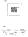
- Figure 4 is a front elevation of a conventional separator 100 used in a fuel cell.
- a number of grooves 120 of about 0.5-2.0 mm in width and depth are formed as shown in Figure 4 on both sides of a plate-shaped separator 100.
- Those grooves 120 function as passages of the reactant gas and as exhaust passages of water generated as result of the reaction.
- said separators 100 not only function as partitions of those cells C, but also function to supply the reactant gas to the adjacent electrode E1 (or E2) through the grooves 120 or to exhaust outside the water generated with the reaction.
- the separators 100 play the role to transmit the electricity generated in the cells C outside.
- the gas shielding property be high so that the reactant gas supplied to the electrodes E1 and E2 (anode side and cathode side) should not mix with each other. Moreover, it is necessary to have excellent corrosion resistance and oxidation resistance so that it is never corroded with the reactant gas. In addition, it is also necessary for the fuel cell to be light, and to have the electrical conduction property. In addition, it is necessary that the separators have sufficient strength to bear the weight of the accumulated cells C.
- An isotropic carbon is used as a material of the separator C which meets the above-mentioned requirements.
- a carbon material R is heated and sintered at 2000 °C or more in an electric furnace (see Figure 5(a)); secondly, it is cut out in the form of a plate (see Figure 5(b)); and then grooves are mechanically formed with an end mill, etc. (see Figure 5(c)).
- isotropic carbon after sintering is very hard and brittle, and consequently, there is a problem in the present art that carrying out the cutting and formation of grooves is too time-consuming.
- the sintering material is prepared by mixing carbon powder with granulated phenol resin functioning as a binder, which material is charged into a mold formed with grooves.
- the components are sintered with a hot plate pressing.
- the sintering of the carbon powder and the formation of grooves may be accomplished simultaneously.
- this method because water is generated from phenol resin during the process of heating and sintering, bubbles which originate in water are inevitably formed in the carbon material after the sintering, thereby impairing the gas shielding property. Accordingly, in this method, there is a problem of having to give a processing of blocking the bubbles after the sintering, which again is very time-consuming.
- a separator manufactured by this method has a structure in which the metallic plate is sandwiched by the carbon materials. Therefore, even if bubbles originating in the phenol resin in the carbon material are generated after the sintering, the obverse side and the reverse side of the separator are not communicable owing to the metallic plate installed in the center, thereby maintaining the gas shielding property as a whole.
- the sintering material is a mixture of the carbon powder and the granulated phenol resin
- the composition tends to become ununiform. It is therefore necessary to add the granulated phenol resin in more than the necessary amount as a binder. Consequently, a number of bubbles which come from the phenol resin are generated.
- the thickness of the carbon material after the sintering tends to be relatively large, and the electric resistance becomes larger thereby.
- the quality of the carbon material after the sintering deteriorates if the sintering material is not uniform. Depending upon the shape of the grooves, the separability from the mold might become difficult, making it hard to remove the carbon material after sintering from the mold.
- the present invention has firstly solved the above-mentioned problems by a method of manufacturing a separator for a polymer electrolyte fuel cell comprising the steps of: arranging a metallic plate provided with plating on the obverse and reverse sides thereof in a mold formed with grooves; charging a sintering material comprising a powder of carbon coated with phenol resin onto both sides of said metallic plate; and integrating said sintering material with said metallic plate by heating and sintering said sintering material in the atmosphere, thereby forming grooves on the surfaces.
- the present invention includes a method of manufacturing a separator for a polymer electrolyte fuel cell comprising the steps of arranging a metallic plate provided with plating on the obverse and reverse sides thereof in a mold formed with grooves; charging a sintering material comprising a powder of carbon coated with phenol resin onto both sides of said metallic plate; and integrating said sintering material with said metallic plate by heating and sintering said sintering material in vacuum, thereby forming grooves on the surfaces.
- the invention further includes a method of manufacturing a separator for a polymer electrolyte fuel cell comprising the steps of: preparing a mold formed with grooves; charging a sintering material comprising a powder of carbon coated with phenol resin, a metal powder, and the same kind of sintering material as mentioned first into said mold in said order; and integrating said sintering materials with said metal powder by heating and sintering said sintering materials in vacuum, thereby forming grooves on the surfaces.
- phenol resin is uniformly distributed in the sintering material, and because the lowest amount of phenol resin required as a binder has to be added, the thus manufactured separator may be homogeneous with high strength. Because the metallic plate does not oxidize when heating and sintering takes place, oxides with a low electrical conduction property are never generated on the surfaces of the separator.
- the separator is manufactured by using a metallic plate with plating on the surfaces, and a sintering material which comprises a carbon powder coated with phenol resin will be explained by way of the first invention.
- Figure 1 is a block diagram of a flow chart showing a method of manufacturing a separator by the first embodiment or aspect of the present invention.
- Figure 2 is a section showing the state of heating and sintering. Firstly, a light metal (aluminum is an example) with a comparatively small specific gravity is formed into a plate; and on the obverse and reverse sides thereof, etching processing, acid treatment, and zinc film coating are performed; and thereafter, a metal which is hard to be oxidized having the coefficient of thermal expansion similar to that of carbon is plated so as to obtain a metallic plate 30.
- a light metal aluminum is an example
- the metallic plate 30 as above-mentioned is plated in a metal mold M in Figure 2, mold which has the ruggedness in the form of the grooves, and the above-mentioned sintering material 20 is filled to both sides of the metallic plate 30, and is sintered in the atmospheric environment.
- the sintering material 20 is integrated with the metallic plate 30, and grooves are formed on the surfaces.
- oxidization will not occur even if heated in the atmosphere because the metal not oxidized easily is plated on the surfaces of the metallic plate 30. Therefore, oxides with a low electrical conduction property are never generated on the surfaces of the thus manufactured separator 10.
- the sintering material 20 which comprises a powder of carbon coated with phenol resin
- the need to mix the carbon powder with the granulated powder of phenol resin may be eliminated unlike the conventional sintering material, and the phenol resin may be more uniformly distributed in the sintering material compared with the conventional sintering material. Therefore, it is easy to prepare a homogeneous carbon material, and the product is easy to be taken out of a mold M, and it is possible to obtain a thin separator 10.
- the phenol resin coated to the surface of the powder of carbon should be adequate as the binder, extra phenol resin need not be added.
- the charging of the carbon material into the mold M increases so that the density of the carbon material after the sintering rises, thereby imparting strength to the carbon material. Also, as the generation of bubbles due to the phenol resin may decrease, the gas shielding property may be improved.
- the same sintering material 20 is filled as the first embodiment to both sides of a metallic plate 30' which is arranged in a mold M which is provided with grooves, and this metallic plate 30' is not provided with any plating. They are sintered in vacuum. As the heating processing is done in vacuum in this particular method, the metallic plate 30' to which plating are not given on the surfaces thereof, does not oxidize at all.
- a third embodiment comprising a method of manufacturing a separator using the sintering material comprising a carbon powder coated with phenol resin and a metallic powder
- the sintering material 20 and the metal powder 32 are filled to a mold M which is provided with grooves, and the materials are sintered in vacuum.
- both sides of the metal powder 32 should be covered by the sintering material 20.
- Charging should be made in the mold M in the order of the sintering material 20, the metal powder 32, and again the sintering material 20.
- the metal powder 32 melts when sintered, the same effect as that of the metallic plates 30 and 30' according to the first and second embodiments respectively are obtained. Because the heating processing is done in vacuum, metal powder 32 is not oxidized at all.
- the effect of sintering material 20 which comprises the carbon powder coated with phenol resin is the same as that of the first embodiment.
- the metallic plates used in the following examples are metallic plates of aluminum, titanium, and magnesium of 0.3 mm with etched surfaces, treated by acid and given with zinc film coatings and processed with the prescribed plating. The thickness of the plating was 5 ⁇ m.
- the metal powders what are available are aluminum, titanium, and magnesium treated with atomization method so as to make the mean particle diameter to be 100 ⁇ m respectively.
- the sintering material what was adopted was artificial graphite particles of 75o ⁇ m or less coated with phenol resin.
- the separators made in the following examples are the same as the one shown in Figure 4. This separator was 100 mm in length, 100 mm in width, 2 mm in thickness, and the grooves shown in Figure 4 within the range of 50 mm in length and 50 mm in width have been formed in the central part on the surface and the back.
- the metallic plate used in example 1 was the an aluminum plate on which electroless nickel/phosphor plating was applied to the surfaces thereof. After this metallic plate was arranged in a mold, and the above mentioned sintering material was filled onto both sides of the metallic plate, it was sintered for 20 minutes under the condition of a pressure of 30 MPa, and the separator shown in Figure 4 was made at 160 °C in the atmospheric environment.
- the metallic plate used in example 2 is a plate to which nickel plating was given to the surfaces of the above-mentioned aluminum plate.
- the metallic plate used in example 3 is a plate to which gold plating was applied to the surface of the above-mentioned aluminum plate.
- the metallic plate used in example 4 is a plate to which platinum plating was applied to the surfaces of the above-mentioned aluminum plate.
- the metallic plate used in example 5 is a plate to which nickel/phosphor plating was given to the surfaces of the above-mentioned titanium plate.
- the metallic plate used in example 6 is a plate to which nickel/phosphor plating was given to the surfaces of the above-mentioned magnesium plate.
- example 7 an aluminum plate to which plating was not given was used in example 7.
- This metallic plate and the sintering material were arranged in a mold, and a separator of the shape shown in Figure 4 was made by sintering in vacuum for 20 minutes by the conditions of 160 °C and a pressure of 30 MPa.
- aluminum metal powder was used as the replacement of the metallic plate.
- the materials were filled in the mold in the order of the sintering material, aluminum metal powder, and the sintering material, and the separator of the shape shown in Figure 4 was made by sintering for 20 minutes in vacuum by the conditions of 160 °C and a pressure of 30 MPa.
- a conventional separator was made with an isotropic carbon turned into a plate of 100 mm in length, 100 mm in width, and 2 mm in thickness and formed with grooves by an end mill within the range of 50 mm in length and 50 mm in width on both sides thereof. This is a comparative example.
- the specific resistance depended on the physical characteristic measuring method (JISR7222) of graphite material, the coefficient of thermal conductivity depended on the laser flash method, respectively, the bending strength depended on the method of bending strength test of hard plastics, and the gas permeability coefficient was measured by the method (JISK7126) of examining the gas permeation degree of plastic films and sheets.
- the separator manufactured by the method of the present invention has the smaller specific resistance, the higher coefficient of thermal conductivity and bending strength, and the lower gas permeability coefficient compared with the conventional separator. Therefore, the electric power generated in the cell and heat can be efficiently transmitted outside when this separator is used, and the reactant gas supplied to the anode side and the cathode side is not mixed easily.
- the method of manufacturing a separator for a polymer electrolyte fuel cell of the present invention it is possible to uniformly distribute the phenol resin in the sintering material by coating the phenol resin as a binder to the surface of a powder of carbon.
- the carbon material after the sintering becomes homogeneous, and there is no need to add phenol resin in the sintering material more than necessary. Therefore, the generation of pores in the carbon material after the sintering may be decreased, and the carbon material becomes high in strength, thereby enabling to manufacture a thinner separator.
- the metallic plate never oxidizes when fired with the sintering material when a metal not oxidized easily is plated on the surface of the metallic plate. Moreover, the metallic plate and the metal powder never oxidize even when the metallic plate and the metal powder to which plating is not given to the surface are used when sintered in vacuum. Therefore, oxides with a low electrical conduction property are never generated on the surfaces of the manufactured separator.
- a separator manufactured by the method of the present inventions is of high strength, it is possible to compose a fuel cell by accumulating a large number of cells. Moreover, because the specific resistance is small, the electric power generated in the cell can be efficiently transmitted outside. In addition, the reactant gas supplied to the anode side and the cathode side is not mixed easily, because it is excellent in the gas shielding property. Moreover, heat generated in the cell can radiate efficiently as the coefficient of thermal conductivity is high.
Landscapes
- Engineering & Computer Science (AREA)
- Chemical & Material Sciences (AREA)
- Life Sciences & Earth Sciences (AREA)
- Manufacturing & Machinery (AREA)
- Sustainable Development (AREA)
- Sustainable Energy (AREA)
- Chemical Kinetics & Catalysis (AREA)
- Electrochemistry (AREA)
- General Chemical & Material Sciences (AREA)
- Mechanical Engineering (AREA)
- Composite Materials (AREA)
- Fuel Cell (AREA)
Applications Claiming Priority (2)
| Application Number | Priority Date | Filing Date | Title |
|---|---|---|---|
| JP2002011730A JP2003217609A (ja) | 2002-01-21 | 2002-01-21 | 固体高分子型燃料電池用セパレータの製造方法 |
| JP2002011730 | 2002-01-21 |
Publications (1)
| Publication Number | Publication Date |
|---|---|
| EP1329967A2 true EP1329967A2 (de) | 2003-07-23 |
Family
ID=19191697
Family Applications (1)
| Application Number | Title | Priority Date | Filing Date |
|---|---|---|---|
| EP02014085A Withdrawn EP1329967A2 (de) | 2002-01-21 | 2002-07-01 | Verfahren zur Herstellung von Brennstoffzellen-Separator für Polymer-Elektrolyt-Brennstoffzelle |
Country Status (6)
| Country | Link |
|---|---|
| US (1) | US6676868B2 (de) |
| EP (1) | EP1329967A2 (de) |
| JP (1) | JP2003217609A (de) |
| KR (1) | KR20030063070A (de) |
| CN (1) | CN1434530A (de) |
| TW (1) | TW548870B (de) |
Families Citing this family (5)
| Publication number | Priority date | Publication date | Assignee | Title |
|---|---|---|---|---|
| US20060234108A1 (en) * | 2003-02-13 | 2006-10-19 | Eiki Tsushima | Method for producing separator of fuel cell |
| KR100858720B1 (ko) * | 2007-05-04 | 2008-09-17 | 김호 | 축전지용 격리판의 제조방법 |
| KR101014034B1 (ko) * | 2008-06-02 | 2011-02-14 | 신선식 | 기능성 물질을 알칼리수로 우려낼 수 있는 음료용기 |
| JP2010180457A (ja) * | 2009-02-06 | 2010-08-19 | Toyota Central R&D Labs Inc | 耐食導電材の製造方法 |
| TWI425699B (zh) * | 2010-01-06 | 2014-02-01 | Ihi Corp | 固體高分子型燃料電池用隔板之製造方法及裝置 |
Family Cites Families (1)
| Publication number | Priority date | Publication date | Assignee | Title |
|---|---|---|---|---|
| JPH04118861A (ja) * | 1990-09-10 | 1992-04-20 | Fuji Electric Co Ltd | 固体電解質型燃料電池およびその製造方法 |
-
2002
- 2002-01-21 JP JP2002011730A patent/JP2003217609A/ja active Pending
- 2002-04-26 CN CN02118619A patent/CN1434530A/zh active Pending
- 2002-06-24 KR KR1020020035363A patent/KR20030063070A/ko not_active Withdrawn
- 2002-06-26 US US10/183,219 patent/US6676868B2/en not_active Expired - Fee Related
- 2002-06-27 TW TW091114130A patent/TW548870B/zh not_active IP Right Cessation
- 2002-07-01 EP EP02014085A patent/EP1329967A2/de not_active Withdrawn
Also Published As
| Publication number | Publication date |
|---|---|
| TW548870B (en) | 2003-08-21 |
| US6676868B2 (en) | 2004-01-13 |
| JP2003217609A (ja) | 2003-07-31 |
| US20030137074A1 (en) | 2003-07-24 |
| KR20030063070A (ko) | 2003-07-28 |
| CN1434530A (zh) | 2003-08-06 |
Similar Documents
| Publication | Publication Date | Title |
|---|---|---|
| KR100824844B1 (ko) | 고체 산화물 연료 전지를 위한 니켈 폼과 니켈 펠트 기반의애노드 | |
| US6893762B2 (en) | Metal-supported tubular micro-fuel cell | |
| US6866958B2 (en) | Ultra-low loadings of Au for stainless steel bipolar plates | |
| KR20080087043A (ko) | 고체 고분자형 연료전지용 세퍼레이터 및 그 제조 방법 | |
| EP0124262A1 (de) | Brennstoffzelle mit einem Elektrolyt aus Karbonatschmelze | |
| US7285347B2 (en) | Anode-supported flat-tubular solid oxide fuel cell stack and fabrication method of the same | |
| JP2004319491A (ja) | 不活性支持体を備える燃料電池あるいは電極 | |
| US20040072054A1 (en) | Hybrid monolithic fuel cell | |
| CN107208294A (zh) | 镍合金多孔体的制造方法 | |
| US11434547B2 (en) | Metal porous material, fuel cell, and method of producing metal porous material | |
| KR20100137477A (ko) | 높은 전력과 높은 기계적 강도를 갖는 저렴한 전해질 지지형 고온 연료 전지용 전해질 | |
| US6676868B2 (en) | Method of manufacturing a separator for a polymer electrolyte fuel cell | |
| US20100307681A1 (en) | Fuel cell separator plate assembly | |
| JPH11297337A (ja) | 固体高分子型燃料電池セパレータ部材及びその製造方法 | |
| EP1836738B1 (de) | Brennstoffzellenanordnung mit separatorplatte | |
| JP3470964B2 (ja) | 燃料電池用セパレータ及びその製造方法 | |
| JP2001068128A (ja) | 燃料電池用セパレータ及びその製造方法 | |
| JPH11185780A (ja) | 円筒状固体電解質型燃料電池セル | |
| JP3405659B2 (ja) | 円筒状固体電解質型燃料電池セル | |
| JP2003303598A (ja) | 固体高分子型燃料電池用セパレータ成形用金型、該セパレータの製造方法およびセパレータ | |
| EP4528859A1 (de) | Bipolare platte einer protonenaustauschmembran-brennstoffzelle und herstellungsverfahren dafür | |
| US20250174673A1 (en) | Solid oxide fuel cells and method of manufacturing the same | |
| JP2002231261A (ja) | 燃料電池用セパレータ及びその製造方法 | |
| DE19630843C1 (de) | Anoden-Elektrolyt-Einheit für Hochtemperatur-Brennstoffzellen ohne scharfe Anoden-Elektrolyt-Grenze sowie deren Herstellung | |
| WO2025115808A1 (ja) | 電気化学セル及びその製造方法 |
Legal Events
| Date | Code | Title | Description |
|---|---|---|---|
| PUAI | Public reference made under article 153(3) epc to a published international application that has entered the european phase |
Free format text: ORIGINAL CODE: 0009012 |
|
| AK | Designated contracting states |
Designated state(s): AT BE BG CH CY CZ DE DK EE ES FI FR GB GR IE IT LI LU MC NL PT SE SK TR |
|
| AX | Request for extension of the european patent |
Extension state: AL LT LV MK RO SI |
|
| STAA | Information on the status of an ep patent application or granted ep patent |
Free format text: STATUS: THE APPLICATION IS DEEMED TO BE WITHDRAWN |
|
| 18D | Application deemed to be withdrawn |
Effective date: 20040803 |