EP1327762A2 - Verfahren, Computerprogramm, Steuer- und/oder Regelgerät zum Betreiben einer Brennkraftmaschine, sowie Brennkraftmaschine - Google Patents
Verfahren, Computerprogramm, Steuer- und/oder Regelgerät zum Betreiben einer Brennkraftmaschine, sowie Brennkraftmaschine Download PDFInfo
- Publication number
- EP1327762A2 EP1327762A2 EP02025973A EP02025973A EP1327762A2 EP 1327762 A2 EP1327762 A2 EP 1327762A2 EP 02025973 A EP02025973 A EP 02025973A EP 02025973 A EP02025973 A EP 02025973A EP 1327762 A2 EP1327762 A2 EP 1327762A2
- Authority
- EP
- European Patent Office
- Prior art keywords
- pressure
- internal combustion
- combustion engine
- fuel
- shut
- Prior art date
- Legal status (The legal status is an assumption and is not a legal conclusion. Google has not performed a legal analysis and makes no representation as to the accuracy of the status listed.)
- Granted
Links
- 238000002485 combustion reaction Methods 0.000 title claims abstract description 72
- 238000000034 method Methods 0.000 title claims description 22
- 239000000446 fuel Substances 0.000 claims abstract description 121
- 230000006870 function Effects 0.000 claims description 15
- 238000011144 upstream manufacturing Methods 0.000 claims description 9
- 238000001514 detection method Methods 0.000 claims description 7
- 230000001105 regulatory effect Effects 0.000 claims description 7
- 238000004590 computer program Methods 0.000 claims description 6
- 230000009467 reduction Effects 0.000 claims description 6
- 239000002828 fuel tank Substances 0.000 claims description 5
- 230000001960 triggered effect Effects 0.000 claims description 2
- 238000009434 installation Methods 0.000 description 5
- 230000006399 behavior Effects 0.000 description 4
- 238000012549 training Methods 0.000 description 4
- 230000015572 biosynthetic process Effects 0.000 description 2
- 238000011161 development Methods 0.000 description 2
- 230000018109 developmental process Effects 0.000 description 2
- 238000012423 maintenance Methods 0.000 description 2
- 230000007257 malfunction Effects 0.000 description 2
- 230000008569 process Effects 0.000 description 2
- 208000027418 Wounds and injury Diseases 0.000 description 1
- 230000004913 activation Effects 0.000 description 1
- 230000000903 blocking effect Effects 0.000 description 1
- 230000001276 controlling effect Effects 0.000 description 1
- 230000006378 damage Effects 0.000 description 1
- 238000003745 diagnosis Methods 0.000 description 1
- 239000003502 gasoline Substances 0.000 description 1
- 208000014674 injury Diseases 0.000 description 1
- 238000005086 pumping Methods 0.000 description 1
- 230000008439 repair process Effects 0.000 description 1
- 238000012360 testing method Methods 0.000 description 1
Images


Classifications
-
- F—MECHANICAL ENGINEERING; LIGHTING; HEATING; WEAPONS; BLASTING
- F02—COMBUSTION ENGINES; HOT-GAS OR COMBUSTION-PRODUCT ENGINE PLANTS
- F02D—CONTROLLING COMBUSTION ENGINES
- F02D41/00—Electrical control of supply of combustible mixture or its constituents
- F02D41/30—Controlling fuel injection
- F02D41/38—Controlling fuel injection of the high pressure type
- F02D41/3809—Common rail control systems
- F02D41/3836—Controlling the fuel pressure
- F02D41/3845—Controlling the fuel pressure by controlling the flow into the common rail, e.g. the amount of fuel pumped
- F02D41/3854—Controlling the fuel pressure by controlling the flow into the common rail, e.g. the amount of fuel pumped with elements in the low pressure part, e.g. low pressure pump
-
- F—MECHANICAL ENGINEERING; LIGHTING; HEATING; WEAPONS; BLASTING
- F02—COMBUSTION ENGINES; HOT-GAS OR COMBUSTION-PRODUCT ENGINE PLANTS
- F02D—CONTROLLING COMBUSTION ENGINES
- F02D41/00—Electrical control of supply of combustible mixture or its constituents
- F02D41/02—Circuit arrangements for generating control signals
- F02D41/04—Introducing corrections for particular operating conditions
- F02D41/042—Introducing corrections for particular operating conditions for stopping the engine
-
- F—MECHANICAL ENGINEERING; LIGHTING; HEATING; WEAPONS; BLASTING
- F02—COMBUSTION ENGINES; HOT-GAS OR COMBUSTION-PRODUCT ENGINE PLANTS
- F02D—CONTROLLING COMBUSTION ENGINES
- F02D41/00—Electrical control of supply of combustible mixture or its constituents
- F02D41/22—Safety or indicating devices for abnormal conditions
- F02D41/221—Safety or indicating devices for abnormal conditions relating to the failure of actuators or electrically driven elements
-
- F—MECHANICAL ENGINEERING; LIGHTING; HEATING; WEAPONS; BLASTING
- F02—COMBUSTION ENGINES; HOT-GAS OR COMBUSTION-PRODUCT ENGINE PLANTS
- F02D—CONTROLLING COMBUSTION ENGINES
- F02D41/00—Electrical control of supply of combustible mixture or its constituents
- F02D41/22—Safety or indicating devices for abnormal conditions
- F02D2041/224—Diagnosis of the fuel system
-
- F—MECHANICAL ENGINEERING; LIGHTING; HEATING; WEAPONS; BLASTING
- F02—COMBUSTION ENGINES; HOT-GAS OR COMBUSTION-PRODUCT ENGINE PLANTS
- F02D—CONTROLLING COMBUSTION ENGINES
- F02D2250/00—Engine control related to specific problems or objectives
- F02D2250/02—Fuel evaporation in fuel rails, e.g. in common rails
Definitions
- the invention initially relates to a method for operating an internal combustion engine in which fuel of at least a fuel pump in at least one pressure range is promoted.
- the fuel system is called a high pressure fuel pump used a 1-cylinder piston pump. Over a Leakage line becomes leakage fuel which passes through the gap between cylinder and piston, from the high pressure fuel pump discharged to the storage container. This relieves the piston seal of the 1-cylinder piston pump used.
- a volume control valve controls in normal operation the delivery rate of the high pressure fuel pump. at switched off internal combustion engine, this valve is open and connects the delivery chamber of the pump with the low pressure area.
- a fundamental problem with fuel systems is that Supply of the combustion chambers of the internal combustion engine with Fuel during starting.
- a valve device ensures that the electrically driven one during the starting process Fuel pump the fuel with increased feed pressure to the Injectors supplies. In many cases this is enough increased feed pressure to the internal combustion engine in start in no time. Due to the increased feed pressure a possible gas bubble in the fuel connection between the electrically driven fuel pump and that of the Internal combustion engine driven fuel pump in many Cases are compressed so that a safe start of the Internal combustion engine is guaranteed.
- the present invention has for its object a method of type mentioned in the beginning so that the start and Operating behavior of a correspondingly operated Internal combustion engine even better at high operating temperatures becomes.
- This object is achieved in a method of the type mentioned at the outset in that a pressure which is higher than the ambient pressure is maintained in the pressure region after the internal combustion engine has been switched off and the functionality of a shut-off valve device, which must be closed in order to maintain the pressure, is checked by detecting the pressure in the pressure range after the internal combustion engine has been switched off and then controlling the shut-off valve device so that it is open when it functions correctly, and then the pressure in the pressure area is again detected at least after a certain time after opening control and is compared with the previously recorded pressure.
- shut-off valve device Because the normally the shut-off valve device is closed when the internal combustion engine is switched off achieved that after switching off the internal combustion engine Pressure in the pressure area can be maintained. By a Maintenance of pressure in the pressure area is avoided that after turning off a hot internal combustion engine of the fuel system can form gas bubbles at all. Such gas bubbles occur when the in Fuel pressure area due to thermal conduction heated by the internal combustion engine. The tendency to Formation of gas bubbles is lower at high pressure than at low pressure. The method according to the invention accelerates thus the start of an operated according to the invention Internal combustion engine considerably.
- shut-off valve device By checking the functionality of the shut-off valve device can be recognized when the Valve device is stuck.
- the valve device is stuck for example in the open state, falls after switching off the pressure in the pressure range drops too quickly from the internal combustion engine and there is a risk of vapor bubble formation in the Fuel system with the above problems next attempt to start the internal combustion engine.
- shut-off valve device If the shut-off valve device is controlled so that it should be open if it functions correctly, a correct one Function of the shut-off valve device provided that Pressure in the pressure range in extreme cases down to ambient pressure fall. Such a drop in pressure is at the The inventive method recorded. That leaves the pressure drop despite appropriate activation of the shut-off valve device from, it can be assumed that the Shut-off valve device works incorrectly.
- the method according to the invention therefore on the one hand Starting behavior of the internal combustion engine in hot start conditions improved and on the other hand the functionality of this provided shut-off valve device by the The method according to the invention is monitored. A faulty one Shut-off valve device can thus be quickly discovered.
- a High pressure fuel pump fuel from one Low pressure area into a high pressure area that promotes Pressure in the high pressure area is detected that leak fuel from the high pressure fuel pump via a leakage line, in which the shutoff valve device is arranged to one Fuel tank that drains off the high pressure area at least when the internal combustion engine is switched off with the Low pressure area fluidically via a flow restrictor is connected, and that a delivery chamber of the high pressure fuel pump when the internal combustion engine is switched off with the Low pressure area is connected.
- the check of the function of the shut-off valve device is particularly easy with this training possible because a pressure sensor is usually in the area anyway the fuel rail is arranged and for Pressure control in the high pressure area is used. Since the Pumping chamber of the high pressure fuel pump when switched off Internal combustion engine fluidly connected to the low pressure area sinks over existing leakages, which is a Form flow restrictor towards the low pressure area, in High pressure area the pressure in this on the in Low pressure range prevailing pressure. Ultimately, can by recording the pressure in the high pressure area Pressure in the low pressure range can be detected.
- a pressure reduction gradient is determined and with a limit value is compared. This may also be the Degree of malfunction can be determined.
- the opening control of the Shut-off valve device only takes place if none Hot setting conditions exist.
- the method according to the invention takes into account the fact worn that when testing the function of the shut-off valve device the pressure upstream of the high pressure fuel pump and in the high pressure area on the in Fuel tank pressure level can drop. at Hot shutdown conditions could cause this when restarting the Internal combustion engine lead to problems.
- the invention also relates to a computer program which for Carrying out the above procedure is appropriate if it is on running on a computer. It becomes special preferred if the computer program is on a memory, is stored in particular on a flash memory.
- the invention relates to a control and / or Control device for operating an internal combustion engine. With this it is advantageous if it comprises a memory on which a computer program of the above type is stored.
- the present invention also relates to a Internal combustion engine, with at least one fuel pump, which conveys into a pressure area with a Pressure detection device for detecting the pressure in the Pressure range, and with a control and / or regulating device.
- the Internal combustion engine includes a low pressure area, which connected to a leakage line via a flow restrictor is in which the shut-off valve device is arranged. This accelerates the release of pressure when the shut-off valve device is open to check their function.
- a high pressure fuel pump which includes at least one defined Has leakage gap through the fuel from High pressure area can get to the low pressure area, and the Pressure detection device is arranged in the high pressure area.
- Such a leakage gap forms the above.
- Flow restrictor which ensures that when the Internal combustion engine the pressure in the high pressure range on the Low pressure range prevailing pressure can drop.
- the Leakage gap must be so small that normal operation the high-pressure fuel pump as little as possible becomes.
- a first in the low pressure range Pressure regulator and a second pressure regulator are present, whereby the opening pressure of the first pressure regulator is less than that Opening pressure of the second pressure regulator, and that the first Pressure regulator on the outlet side upstream of the shut-off valve device opens into the leakage line.
- This is it is possible to increase the pressure in the low pressure range in the Maintenance of the engine to maintain. in the In contrast, normal operation of the internal combustion engine and when the function of the shut-off valve device can be checked pressure in the low pressure range is determined by the first Pressure regulator regulated, d. H. he's on a lower one Level. As a result, the hot start behavior of the Internal combustion engine improved and safe at the same time Check the function of the shut-off valve device allows.
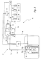
- an internal combustion engine carries this overall Reference numeral 10. It includes a fuel system 12 a low pressure area 14 and a high pressure area 16.
- the low pressure region 14 of the fuel system 12 comprises a reservoir 18, from which an electrically driven Low pressure fuel pump 20 delivers fuel.
- the Low pressure fuel pump 20 delivers over Check valve 22 into a low pressure fuel line 24. This leads to a high-pressure fuel pump 26.
- This is designed as a 1-cylinder piston pump with one Delivery chamber 28, which is upstream via a suction valve 30 is connected to the low pressure fuel line 24.
- the delivery chamber 28 is downstream via an outlet valve 32 connected to a fuel rail 34.
- On these are connected to a plurality of injectors 36, which the Fuel directly in combustion chambers 38 assigned to them inject.
- a pressure relief valve 40 may be excess Fuel from the fuel rail 34 for Return low pressure fuel line 24.
- the pressure in the fuel rail 34 is from a pressure sensor 42 detected.
- the high pressure fuel pump 26 includes a flow restrictor 44, via the fuel from the fuel rail 34 in the flow chamber 28 can flow.
- the flow restrictor 44 is like this dimensioned that the efficiency of the high pressure fuel pump 26 is only marginally reduced. On the other hand, it enables, as further below in detail is shown with the internal combustion engine 10 switched off a comparatively rapid reduction in pressure in the high pressure range 16 and the fuel rail 34.
- the low pressure region 14 extends from the check valve 22 the fuel line 14 to the suction valve 30 and in some Operating conditions up to the funding area 28.
- the High pressure area 16 extends from injectors 36 the fuel rail 34 to the exhaust valve 32, in make operating conditions up to the funding room 28.
- the high pressure fuel pump 26 further includes a Volume control valve 46. This is a 2/2-way valve, with which the delivery chamber 28 with the low-pressure fuel line 24 can be connected.
- Quantity control valve 46 delivers high-pressure fuel pump 26 So not in the fuel rail 34, but back into the low pressure fuel line 24. Via the Opening duration of the quantity control valve 46 per delivery cycle of the High pressure fuel pump 26 may be the one of the high pressure fuel pump 26 into the fuel rail 34 delivered fuel quantity can be set.
- the Quantity control valve 46 is de-energized, that is also at stationary or switched off internal combustion engine 10, open.
- a leakage line 48 leads from the delivery chamber 28 back to the Storage container 18. Via the leakage line 48 can Leakage fuel from high pressure fuel pump 26 be dissipated, which relieves one in the figure Piston seal, not shown, and thus to a Extending the life of the high pressure fuel pump 26 leads.
- a shut-off valve 50 is located in the leakage line 48 arranged. Via a flow restrictor 52 Leakage line 48 with the immediately upstream from Suction valve 30 located area of the low pressure fuel line 24 connected.
- the electric low pressure fuel pump 20 is part of one Tank installation unit 54.
- a pressure regulator 56 arranged the pressure in the low pressure fuel line 24 limited to a certain value and with on the outlet side is connected to a lower region of the tank installation unit 54.
- a control device 58 receives signals from the pressure sensor 42 and controls the shutoff valve 50 and the flow control valve 46 on.
- the internal combustion engine 10 is operated as follows:
- the electric low-pressure fuel pump delivers during normal operation 20 fuel from the reservoir 18 with a pressure of approximately 6 bar to the high pressure fuel pump 26. There the fuel continues to be at a very high pressure (currently up to 200 bar and at gasoline engines Diesel internal combustion engines currently compressed up to 2000 bar) and promoted into the fuel rail 34. From there it reaches the combustion chambers 38 via the injectors 36 Volume control valve 46 is operated by control and regulating device 58 depending on the pressure in the fuel rail 34 controlled, which is detected by the pressure sensor 42. The Shut-off valve 50 is open.
- the Flow control valve 46 is open when de-energized and the shut-off valve 50 closed. The flows through the flow restrictor 44 Fuel from the fuel rail 34 first in the Delivery room and from there via the opened quantity control valve 46 into the low pressure fuel line 24.
- shut-off valve 50 Function of the shut-off valve 50 according to a method are checked, which is shown in FIG. 2:
- Block 62 After a start block 60 it is checked in block 62 whether the Internal combustion engine 10 is turned off, the control and Control unit is in a run-on state and that Shutoff valve 50 is closed when de-energized. Is that the case, a measured value of the pressure sensor 42 is recorded in block 64. in the Block 66 is the control valve 58 the shutoff valve 50 energized. After a certain period of time, Block 68 again records the measured value of pressure sensor 42. Then the block valve 50 is again in block 70 switched off.
- the difference dp between the two in blocks 64 and 68 measured pressures and im Block 74 compared to a threshold GW. Is the difference dp greater than the limit GW, it means that the Current supply to the shut-off valve 50 in block 66 actually increases an opening of the shut-off valve 50 and a corresponding one Pressure drop in the fuel rail 34 has resulted.
- FIG. 1 A major difference from that shown in Fig. 3 Internal combustion engine 10 relates to that shown in FIG. 1 the arrangement of the shut-off valve 50: This is in the Fig. 3 internal combustion engine 10 part of Tank installation unit 54. Furthermore, there is not only one pressure regulator 56 provided, but there is a first pressure regulator 56a and a second pressure regulator 56b is present. Here is the opening pressure of the pressure regulator 56a is greater than the opening pressure of the Pressure regulator 56b. On the outlet side, the pressure regulator 56a is direct connected to the reservoir 18, whereas the Pressure regulator 56b upstream of the outlet Shut-off valve 50 opens into the leakage line 48. hereby the following is done:
Landscapes
- Engineering & Computer Science (AREA)
- Chemical & Material Sciences (AREA)
- Combustion & Propulsion (AREA)
- Mechanical Engineering (AREA)
- General Engineering & Computer Science (AREA)
- Fuel-Injection Apparatus (AREA)
- Electrical Control Of Air Or Fuel Supplied To Internal-Combustion Engine (AREA)
- Combined Controls Of Internal Combustion Engines (AREA)
Abstract
Description
die Funktionsfähigkeit einer Absperr-Ventileinrichtung, welche zur Aufrechterhaltung des Drucks geschlossen sein muss, dadurch überprüft wird, dass der Druck in dem Druckbereich nach dem Abstellen der Brennkraftmaschine erfasst und dann die Absperr-Ventileinrichtung so angesteuert wird, dass sie bei korrekter Funktion geöffnet ist, und dann der Druck in dem Druckbereich mindestens nach einem bestimmten Zeitablauf nach der Öffnungsansteuerung nochmals erfasst und mit dem zuvor erfassten Druck verglichen wird.
- Figur 1
- eine schematische Darstellung eines ersten Ausführungsbeispiels einer Brennkraftmaschine mit einer Hochdruck-Kraftstoffpumpe und einer Leckageleitung, welche mittels einer Absperr-Ventileinrichtung gesperrt werden kann;
- Figur 2
- ein Flussdiagramm, welches ein Verfahren zur Überprüfung der Funktion der Absperr-Ventileinrichtung von Fig. 1 zeigt; und
- Figur 3
- eine schematische Darstellung ähnlich Fig. 1 eines zweiten Ausführungsbeispiels einer Brennkraftmaschine.
Claims (13)
- Verfahren zum Betreiben einer Brennkraftmaschine (10), bei dem Kraftstoff von mindestens einer Kraftstoffpumpe (26) in mindestens einen Druckbereich (16) gefördert wird, dadurch gekennzeichnet, dass ein gegenüber Umgebungsdruck erhöhter Druck in dem Druckbereich (16) nach dem Abstellen der Brennkraftmaschine (10) aufrechterhalten und die Funktionsfähigkeit einer Absperr-Ventileinrichtung (50), welche zur Aufrechterhaltung des Drucks geschlossen sein muss, dadurch überprüft wird, dass der Druck in dem Druckbereich (16) nach dem Abstellen der Brennkraftmaschine (10) erfasst (64) und dann die Absperr-Ventileinrichtung (50) so angesteuert wird (66), dass sie bei korrekter Funktion geöffnet ist, und dann der Druck in dem Druckbereich (16) mindestens nach einem bestimmten Zeitablauf nach der Öffnungsansteuerung (66) nochmals erfasst (68) und mit dem zuvor erfassten Druck verglichen wird (74).
- Verfahren nach Anspruch 1, dadurch gekennzeichnet, dass eine Hochdruck-Kraftstoffpumpe (26) Kraftstoff von einem Niederdruckbereich (14) in einen Hochdruckbereich (16) fördert, dass der Druck im Hochdruckbereich (16) erfasst wird, dass Leckagekraftstoff aus der Hochdruck-Kraftstoffpumpe (16) über eine Leckageleitung (48), in welcher die Absperr-Ventileinrichtung (50) angeordnet ist, zu einem Kraftstoffbehälter (18) abgeführt wird, dass der Hochdruckbereich (16) mindestens bei abgeschalteter Brennkraftmaschine (10) mit dem Niederdruckbereich (14) über eine Strömungsdrossel (44) fluidisch verbunden ist, und dass ein Förderraum (28) der Hochdruck-Kraftstoffpumpe (16) bei abgeschalteter Brennkraftmaschine (10) mit dem Niederdruckbereich (14) verbunden wird.
- Verfahren nach einem der Ansprüche 1 oder 2, dadurch gekennzeichnet, dass eine Differenz (dp) zwischen dem Druck vor der Öffnungsansteuerung (66) und dem Druck nach der Öffnungsansteuerung (66) der Absperr-Ventileinrichtung (50) gebildet (72) und mit einem Grenzwert (GW) verglichen wird (74).
- Verfahren nach einem der vorhergehenden Ansprüche, dadurch gekennzeichnet, dass ein Druckabbaugradient bestimmt und mit einem Grenzwert verglichen wird.
- Verfahren nach einem der Ansprüche 3 oder 4, dadurch gekennzeichnet, dass dann, wenn die Differenz (dp) und/oder der Druckabbaugradient kleiner als oder gleich wie der entsprechende Grenzwert (GW) ist, ein Eintrag in einen Fehlerspeicher erfolgt (82) und/oder ein Alarm ausgelöst wird.
- Verfahren nach einem der vorhergehenden Ansprüche, dadurch gekennzeichnet, dass die Öffnungsansteuerung (66) der Absperr-Ventileinrichtung (50) nur dann erfolgt, wenn keine Heißabstellbedingungen vorliegen.
- Computerprogramm, dadurch gekennzeichnet, dass es zur Durchführung des Verfahrens nach einem der vorhergehenden Ansprüche geeignet ist, wenn es auf einem Computer ausgeführt wird.
- Computerprogramm nach Anspruch 7, dadurch gekennzeichnet, dass es auf einem Speicher, insbesondere auf einem Flash-Memory, abgespeichert ist.
- Steuer- und/oder Regelgerät (58) zum Betreiben einer Brennkraftmaschine (10), dadurch gekennzeichnet, dass es einen Speicher umfasst, auf dem ein Computerprogramm nach einem der Ansprüche 7 oder 8 abgespeichert ist.
- Brennkraftmaschine (10), mit mindestens einer Kraftstoffpumpe (26), welche in einen Druckbereich (16) fördert, mit einer Druckerfassungseinrichtung (42) zur Erfassung des Drucks im Druckbereich (26), und mit einem Steuer- und/oder Regelgerät (58), dadurch gekennzeichnet, dass sie eine Einrichtung (50) umfasst, welche dafür sorgt, dass bei abgeschalteter Brennkraftmaschine (10) in dem Druckbereich (16) ein gegenüber Umgebungsdruck erhöhter Druck aufrechterhalten werden kann, wobei die Einrichtung eine Absperr-Ventileinrichtung (50) umfasst, welche zur Aufrechterhaltung des Drucks geschlossen sein muss, und dass das Steuer- und/oder Regelgerät (58) so ausgebildet ist, dass es nach dem Abstellen der Brennkraftmaschine (10) ein Drucksignal von der Druckerfassungseinrichtung (42) empfängt (64), dann die Absperr-Ventileinrichtung (50) so ansteuert (66), dass diese bei korrekter Funktion geöffnet ist, dann mindestens nach einem bestimmten Zeitablauf nach der Öffnungsansteuerung (66) nochmals ein Drucksignal von der Druckerfassungseinrichtung (42) empfängt (68), und die beiden Drucksignale miteinander vergleicht (72).
- Brennkraftmaschine (10) nach Anspruch 9, dadurch gekennzeichnet, dass sie einen Niederdruckbereich (14) umfasst, welcher über eine Strömungsdrossel (52) mit einer Leckageleitung (48) verbunden ist, in der die Absperr-Ventileinrichtung (50) angeordnet ist.
- Brennkraftmaschine (10) nach Anspruch 11, dadurch gekennzeichnet, dass sie eine Hochdruck-Kraftstoffpumpe (26) umfasst, welche mindestens einen definierten Leckagespalt (44) aufweist, durch den Kraftstoff vom Hochdruckbereich (16) zum Niederdruckbereich (14) gelangen kann, und die Druckerfassungseinrichtung (42) im Hochdruckbereich (16) angeordnet ist.
- Brennkraftmaschine (10) nach einem der Ansprüche 11 oder 12, dadurch gekennzeichnet, dass im Niederdruckbereich (14) ein erster Druckregler (56b) und ein zweiter Druckregler (56a) vorhanden sind, wobei der Öffnungsdruck des ersten Druckreglers (56b) kleiner ist als der Öffnungsdruck des zweiten Druckreglers (56a), und dass der erste Druckregler (56b) auslassseitig stromaufwärts von der Absperrventileinrichtung (50) in die Leckageleitung (48) mündet.
Applications Claiming Priority (2)
| Application Number | Priority Date | Filing Date | Title |
|---|---|---|---|
| DE2002100829 DE10200829A1 (de) | 2002-01-11 | 2002-01-11 | Verfahren, Computerprogramm, Steuer- und/oder Regelgerät zum Betreiben einer Brennkraftmaschine, sowie Brennkraftmaschine |
| DE10200829 | 2002-01-11 |
Publications (3)
| Publication Number | Publication Date |
|---|---|
| EP1327762A2 true EP1327762A2 (de) | 2003-07-16 |
| EP1327762A3 EP1327762A3 (de) | 2005-09-07 |
| EP1327762B1 EP1327762B1 (de) | 2007-01-24 |
Family
ID=7711908
Family Applications (1)
| Application Number | Title | Priority Date | Filing Date |
|---|---|---|---|
| EP20020025973 Expired - Lifetime EP1327762B1 (de) | 2002-01-11 | 2002-11-21 | Verfahren, Computerprogramm, Steuer- und/oder Regelgerät zum Betreiben einer Brennkraftmaschine, sowie Brennkraftmaschine |
Country Status (3)
| Country | Link |
|---|---|
| EP (1) | EP1327762B1 (de) |
| JP (1) | JP2003239817A (de) |
| DE (2) | DE10200829A1 (de) |
Cited By (2)
| Publication number | Priority date | Publication date | Assignee | Title |
|---|---|---|---|---|
| US7707868B2 (en) * | 2006-09-15 | 2010-05-04 | Robert Bosch Gmbh | Method for determining the operability of a pressure sensor |
| EP2546501A1 (de) * | 2011-07-11 | 2013-01-16 | Toyota Jidosha Kabushiki Kaisha | Fehlfunktionserkennungsvorrichtung für Motoren und Fehlfunktionserkennungsverfahren für Motoren |
Families Citing this family (2)
| Publication number | Priority date | Publication date | Assignee | Title |
|---|---|---|---|---|
| JP4407611B2 (ja) * | 2005-10-06 | 2010-02-03 | 株式会社デンソー | 燃料噴射制御装置 |
| JP2010156297A (ja) * | 2008-12-29 | 2010-07-15 | Denso Corp | 燃料供給装置 |
Family Cites Families (7)
| Publication number | Priority date | Publication date | Assignee | Title |
|---|---|---|---|---|
| JP3345933B2 (ja) * | 1993-01-19 | 2002-11-18 | 株式会社デンソー | 蓄圧式燃料噴射装置 |
| DE19513158A1 (de) * | 1995-04-07 | 1996-10-10 | Bosch Gmbh Robert | Einrichtung zur Erkennung eines Lecks in einem Kraftstoffversorgungssystem |
| JP3842331B2 (ja) * | 1995-05-26 | 2006-11-08 | ローベルト ボツシユ ゲゼルシヤフト ミツト ベシユレンクテル ハフツング | 内燃機関の燃料供給のための燃料供給装置及び内燃機関を運転する方法 |
| DE19539883B4 (de) * | 1995-05-26 | 2011-06-01 | Robert Bosch Gmbh | Kraftstoffversorgungsanlage und Verfahren zum Betreiben einer Brennkraftmaschine |
| DE19703891B4 (de) * | 1997-02-03 | 2008-07-31 | Robert Bosch Gmbh | Verfahren und Vorrichtung zur Erkennung einer Leckage |
| DE19727794C1 (de) * | 1997-06-30 | 1999-01-28 | Siemens Ag | Verfahren zum Überprüfen einer Kraftstoffversorgung |
| DE19934648C1 (de) * | 1999-07-23 | 2000-10-26 | Daimler Chrysler Ag | Kraftstoff-Versorgungssystem |
-
2002
- 2002-01-11 DE DE2002100829 patent/DE10200829A1/de not_active Ceased
- 2002-11-21 DE DE50209338T patent/DE50209338D1/de not_active Expired - Fee Related
- 2002-11-21 EP EP20020025973 patent/EP1327762B1/de not_active Expired - Lifetime
-
2003
- 2003-01-14 JP JP2003006377A patent/JP2003239817A/ja not_active Ceased
Cited By (2)
| Publication number | Priority date | Publication date | Assignee | Title |
|---|---|---|---|---|
| US7707868B2 (en) * | 2006-09-15 | 2010-05-04 | Robert Bosch Gmbh | Method for determining the operability of a pressure sensor |
| EP2546501A1 (de) * | 2011-07-11 | 2013-01-16 | Toyota Jidosha Kabushiki Kaisha | Fehlfunktionserkennungsvorrichtung für Motoren und Fehlfunktionserkennungsverfahren für Motoren |
Also Published As
| Publication number | Publication date |
|---|---|
| DE50209338D1 (de) | 2007-03-15 |
| EP1327762A3 (de) | 2005-09-07 |
| DE10200829A1 (de) | 2003-07-31 |
| EP1327762B1 (de) | 2007-01-24 |
| JP2003239817A (ja) | 2003-08-27 |
Similar Documents
| Publication | Publication Date | Title |
|---|---|---|
| EP1360406B1 (de) | Kraftstoffsystem, verfahren zum betreiben des kraftstoff-systems, computerprogramm sowie steuer- und/oder regelgerät zur steuerung des kraftstoffsystems | |
| DE102010000221B4 (de) | Druck-Akkumulations-Kraftstoffeinspritzvorrichtung | |
| DE60109966T2 (de) | Methode zum Festsetzen des Betriebs des Einspritzungsystems mit Verteilerleitung für einen Verbrennungsmotor | |
| DE19626689C1 (de) | Verfahren und Vorrichtung zur Überwachung eines Einspritzsystems | |
| DE10155247B4 (de) | Einspritzanlage mit Notlauffunktion | |
| DE102013021921B4 (de) | Dual-Brennstoff-Common-Rail-System und Betriebsverfahren dafür im Dieselmodus | |
| DE19521791A1 (de) | Verfahren zum Erkennen von Betriebsstörungen in einer Kraftstoffeinspritzanlage einer Brennkraftmaschine | |
| DE102006047181A1 (de) | Krafstoffeinspritzsystem, das zum Gewährleisten einer verbesserten Zuverlässigkeit zum Diagnostizieren eines Ventils ausgelegt ist | |
| EP1348072B1 (de) | Verfahren, computerprogram und steuer- und/oder regelgerät zum betreiben einer brennkraftmaschine sowie brennkraftmaschine | |
| DE102009002945A1 (de) | Kraftstoffliefersteuervorrichtung und Kraftstoffliefergerät, das diese verwendet | |
| EP1427931B1 (de) | Verfahren, computerprogramm, steuer- und/oder regelgerät zum betreiben einer brennkraftmaschine sowie kraftstoffsystem für eine brennkraftmaschine | |
| DE10061855C2 (de) | Verfahren, Computerprogramm und Steuer- und/oder Regelgerät zum Betreiben einer Brennkraftmaschine, sowie Brennkraftmaschine | |
| WO2016058733A1 (de) | Verfahren zum betreiben eines kraftstoffversorgungssystems für eine brennkraftmaschine | |
| DE102004003316A1 (de) | Kraftstoffeinspritzsystem der Drucksammelbauart | |
| EP1432903B1 (de) | Verfahren sowie steuer- und/oder regelgerät zum betreiben einer brennkraftmaschine mit piezoelektrisch betätigten kraftstoffeinspritzventilen | |
| EP1327762B1 (de) | Verfahren, Computerprogramm, Steuer- und/oder Regelgerät zum Betreiben einer Brennkraftmaschine, sowie Brennkraftmaschine | |
| EP1325222B1 (de) | Verfahren zur diagnose eines ventils in einem kraftstoffversorgungssystem einer brennkraftmaschine | |
| DE102010004215B4 (de) | Vorrichtung zur Verhinderung des Absterbens des Motors bei einem mit einem Dieseleinspritzsystem ausgestatteten Fahrzeug | |
| DE10155249C1 (de) | Einspritzanlage sowie Verfahren zur Regelung einer Kraftstoffpunpe | |
| EP2971746B1 (de) | Verfahren zur entlüftung einer kraftstoffversorgungsleitung und brennkraftmaschine | |
| DE102005043684A1 (de) | Kraftstoffdruckregelung bei Schubabschaltung | |
| WO2004027250A1 (de) | Kraftstoffeinspritzanlage für brennkraftmaschinen | |
| EP1226349B1 (de) | Verfahren zum ablassen des kraftstoffdrucks in einem rücklauffreien kraftstoffversorgungssystem | |
| DE102007061228A1 (de) | Verfahren zum Betreiben eines Kraftstoffsystems einer Brennkraftmaschine | |
| DE102021204058B3 (de) | Verfahren und Vorrichtung zur Diagnose eines Absperrventils eines Fluidsystems |
Legal Events
| Date | Code | Title | Description |
|---|---|---|---|
| PUAI | Public reference made under article 153(3) epc to a published international application that has entered the european phase |
Free format text: ORIGINAL CODE: 0009012 |
|
| AK | Designated contracting states |
Designated state(s): AT BE BG CH CY CZ DE DK EE ES FI FR GB GR IE IT LI LU MC NL PT SE SK TR |
|
| AX | Request for extension of the european patent |
Extension state: AL LT LV MK RO SI |
|
| PUAL | Search report despatched |
Free format text: ORIGINAL CODE: 0009013 |
|
| AK | Designated contracting states |
Kind code of ref document: A3 Designated state(s): AT BE BG CH CY CZ DE DK EE ES FI FR GB GR IE IT LI LU MC NL PT SE SK TR |
|
| AX | Request for extension of the european patent |
Extension state: AL LT LV MK RO SI |
|
| 17P | Request for examination filed |
Effective date: 20060307 |
|
| AKX | Designation fees paid |
Designated state(s): DE FR IT |
|
| GRAP | Despatch of communication of intention to grant a patent |
Free format text: ORIGINAL CODE: EPIDOSNIGR1 |
|
| GRAS | Grant fee paid |
Free format text: ORIGINAL CODE: EPIDOSNIGR3 |
|
| GRAA | (expected) grant |
Free format text: ORIGINAL CODE: 0009210 |
|
| AK | Designated contracting states |
Kind code of ref document: B1 Designated state(s): DE FR IT |
|
| REF | Corresponds to: |
Ref document number: 50209338 Country of ref document: DE Date of ref document: 20070315 Kind code of ref document: P |
|
| ET | Fr: translation filed | ||
| PLBE | No opposition filed within time limit |
Free format text: ORIGINAL CODE: 0009261 |
|
| STAA | Information on the status of an ep patent application or granted ep patent |
Free format text: STATUS: NO OPPOSITION FILED WITHIN TIME LIMIT |
|
| 26N | No opposition filed |
Effective date: 20071025 |
|
| PGFP | Annual fee paid to national office [announced via postgrant information from national office to epo] |
Ref country code: IT Payment date: 20081125 Year of fee payment: 7 |
|
| PGFP | Annual fee paid to national office [announced via postgrant information from national office to epo] |
Ref country code: FR Payment date: 20081118 Year of fee payment: 7 |
|
| PGFP | Annual fee paid to national office [announced via postgrant information from national office to epo] |
Ref country code: DE Payment date: 20090126 Year of fee payment: 7 |
|
| REG | Reference to a national code |
Ref country code: FR Ref legal event code: ST Effective date: 20100730 |
|
| PG25 | Lapsed in a contracting state [announced via postgrant information from national office to epo] |
Ref country code: FR Free format text: LAPSE BECAUSE OF NON-PAYMENT OF DUE FEES Effective date: 20091130 |
|
| PG25 | Lapsed in a contracting state [announced via postgrant information from national office to epo] |
Ref country code: DE Free format text: LAPSE BECAUSE OF NON-PAYMENT OF DUE FEES Effective date: 20100601 |
|
| PG25 | Lapsed in a contracting state [announced via postgrant information from national office to epo] |
Ref country code: IT Free format text: LAPSE BECAUSE OF NON-PAYMENT OF DUE FEES Effective date: 20091121 |