EP1326115A1 - Stativ mit einer automatischen Balanciereinrichtung - Google Patents
Stativ mit einer automatischen Balanciereinrichtung Download PDFInfo
- Publication number
- EP1326115A1 EP1326115A1 EP02100753A EP02100753A EP1326115A1 EP 1326115 A1 EP1326115 A1 EP 1326115A1 EP 02100753 A EP02100753 A EP 02100753A EP 02100753 A EP02100753 A EP 02100753A EP 1326115 A1 EP1326115 A1 EP 1326115A1
- Authority
- EP
- European Patent Office
- Prior art keywords
- adjustment
- electric motor
- stand
- stand according
- balance
- Prior art date
- Legal status (The legal status is an assumption and is not a legal conclusion. Google has not performed a legal analysis and makes no representation as to the accuracy of the status listed.)
- Granted
Links
- 238000005259 measurement Methods 0.000 claims abstract description 14
- 230000033001 locomotion Effects 0.000 claims abstract description 11
- 230000007704 transition Effects 0.000 claims 1
- 238000000034 method Methods 0.000 description 17
- 238000010586 diagram Methods 0.000 description 7
- 230000003068 static effect Effects 0.000 description 5
- 238000005452 bending Methods 0.000 description 4
- 238000010276 construction Methods 0.000 description 2
- 238000011161 development Methods 0.000 description 2
- 230000018109 developmental process Effects 0.000 description 2
- 238000006073 displacement reaction Methods 0.000 description 2
- 239000000523 sample Substances 0.000 description 2
- 240000003517 Elaeocarpus dentatus Species 0.000 description 1
- 230000001419 dependent effect Effects 0.000 description 1
- 238000001514 detection method Methods 0.000 description 1
- 238000000386 microscopy Methods 0.000 description 1
- 230000003287 optical effect Effects 0.000 description 1
- 230000000284 resting effect Effects 0.000 description 1
- 239000007787 solid Substances 0.000 description 1
- 230000001960 triggered effect Effects 0.000 description 1
- 238000005303 weighing Methods 0.000 description 1
Images


Classifications
-
- F—MECHANICAL ENGINEERING; LIGHTING; HEATING; WEAPONS; BLASTING
- F16—ENGINEERING ELEMENTS AND UNITS; GENERAL MEASURES FOR PRODUCING AND MAINTAINING EFFECTIVE FUNCTIONING OF MACHINES OR INSTALLATIONS; THERMAL INSULATION IN GENERAL
- F16M—FRAMES, CASINGS OR BEDS OF ENGINES, MACHINES OR APPARATUS, NOT SPECIFIC TO ENGINES, MACHINES OR APPARATUS PROVIDED FOR ELSEWHERE; STANDS; SUPPORTS
- F16M11/00—Stands or trestles as supports for apparatus or articles placed thereon ; Stands for scientific apparatus such as gravitational force meters
- F16M11/02—Heads
- F16M11/18—Heads with mechanism for moving the apparatus relatively to the stand
-
- A—HUMAN NECESSITIES
- A61—MEDICAL OR VETERINARY SCIENCE; HYGIENE
- A61B—DIAGNOSIS; SURGERY; IDENTIFICATION
- A61B90/00—Instruments, implements or accessories specially adapted for surgery or diagnosis and not covered by any of the groups A61B1/00 - A61B50/00, e.g. for luxation treatment or for protecting wound edges
- A61B90/20—Surgical microscopes characterised by non-optical aspects
- A61B90/25—Supports therefor
-
- A—HUMAN NECESSITIES
- A61—MEDICAL OR VETERINARY SCIENCE; HYGIENE
- A61B—DIAGNOSIS; SURGERY; IDENTIFICATION
- A61B90/00—Instruments, implements or accessories specially adapted for surgery or diagnosis and not covered by any of the groups A61B1/00 - A61B50/00, e.g. for luxation treatment or for protecting wound edges
- A61B90/50—Supports for surgical instruments, e.g. articulated arms
-
- G—PHYSICS
- G02—OPTICS
- G02B—OPTICAL ELEMENTS, SYSTEMS OR APPARATUS
- G02B7/00—Mountings, adjusting means, or light-tight connections, for optical elements
- G02B7/001—Counterbalanced structures, e.g. surgical microscopes
-
- A—HUMAN NECESSITIES
- A61—MEDICAL OR VETERINARY SCIENCE; HYGIENE
- A61B—DIAGNOSIS; SURGERY; IDENTIFICATION
- A61B90/00—Instruments, implements or accessories specially adapted for surgery or diagnosis and not covered by any of the groups A61B1/00 - A61B50/00, e.g. for luxation treatment or for protecting wound edges
- A61B90/50—Supports for surgical instruments, e.g. articulated arms
- A61B2090/5025—Supports for surgical instruments, e.g. articulated arms with a counter-balancing mechanism
-
- A—HUMAN NECESSITIES
- A61—MEDICAL OR VETERINARY SCIENCE; HYGIENE
- A61B—DIAGNOSIS; SURGERY; IDENTIFICATION
- A61B90/00—Instruments, implements or accessories specially adapted for surgery or diagnosis and not covered by any of the groups A61B1/00 - A61B50/00, e.g. for luxation treatment or for protecting wound edges
- A61B90/20—Surgical microscopes characterised by non-optical aspects
-
- F—MECHANICAL ENGINEERING; LIGHTING; HEATING; WEAPONS; BLASTING
- F16—ENGINEERING ELEMENTS AND UNITS; GENERAL MEASURES FOR PRODUCING AND MAINTAINING EFFECTIVE FUNCTIONING OF MACHINES OR INSTALLATIONS; THERMAL INSULATION IN GENERAL
- F16M—FRAMES, CASINGS OR BEDS OF ENGINES, MACHINES OR APPARATUS, NOT SPECIFIC TO ENGINES, MACHINES OR APPARATUS PROVIDED FOR ELSEWHERE; STANDS; SUPPORTS
- F16M2200/00—Details of stands or supports
- F16M2200/04—Balancing means
- F16M2200/044—Balancing means for balancing rotational movement of the undercarriage
-
- F—MECHANICAL ENGINEERING; LIGHTING; HEATING; WEAPONS; BLASTING
- F16—ENGINEERING ELEMENTS AND UNITS; GENERAL MEASURES FOR PRODUCING AND MAINTAINING EFFECTIVE FUNCTIONING OF MACHINES OR INSTALLATIONS; THERMAL INSULATION IN GENERAL
- F16M—FRAMES, CASINGS OR BEDS OF ENGINES, MACHINES OR APPARATUS, NOT SPECIFIC TO ENGINES, MACHINES OR APPARATUS PROVIDED FOR ELSEWHERE; STANDS; SUPPORTS
- F16M2200/00—Details of stands or supports
- F16M2200/06—Arms
- F16M2200/068—Arms being part of the undercarriage
Definitions
- the invention relates to a tripod with an automatic balancing device.
- tripods used the weight of the microscope by means of automatic Balancers balance. In doing so, depending on forces or Moments that arise due to an imbalance, balance weights shifted, so that the load (microscope and its accessories) and the balance weights in come to a balanced state. This condition is reached when a User can move the microscope on the tripod like weightless through the room.
- the automatic balancing also brakes provided that block the tripod in a selected position in space.
- tripods are used during the automatic balancing process braked by at least one of the brakes. Then the imbalance measured (e.g., by measuring buckling, bending or torques or forces become). A computer then sets-eg. on the hand of a table-solid, ob the tripod is in balance or unbalance. If the tripod is in balance, so an adjustment command for an adjustment motor is generated, the at least one of Balancing weights adjusted so that the imbalance becomes smaller. If needed this process repeats until the imbalance is reduced to a minimum.
- This automatic balancing method is because the measurement of imbalance in the braked resting state of the load and the balance weight, a static measuring and control method.
- the inventor calls the known Balanciertechnisch therefore static Balanciertechnisch.
- Balancing methods are used, for example, in the OHS by Leica-Microsystems (Prospectus No. 10M15010EN) and applied to the structure of DE-4320443-C2.
- the invention is therefore based on the object to provide a device which avoids the stated disadvantages by the automatic Balancing be accelerated, or reduces the time required for this and, if possible, the step by step resolution of the balancing process into one flowing process to be transferred.
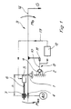
- a balanceable tripod according to the invention comprises a pivot bearing 1 which, in relation to an only indicated stand 2, is basically fixed in position and position.
- the microscope or the load G is suspended on an arm 14 of a double-arm carrier 3, which is pivotally mounted in the pivot bearing 1. Facing away from the load G on the other arm (effective lever arm h) of the carrier 3 is a balance weight AG, which is displaceable for balancing. It depends on a slide 4, which is mounted displaceably on the carrier 3.
- An electric motor 5, which is fixedly mounted on the carrier 3, adjusted by a spindle 6, which cooperates with a nut 7, the distance h between balancing weight AG and pivot bearing 1.
- the nut 7 is rigidly connected to the slider 4.
- the tripod is balanced when the tilting moment MG of the load is equal to the compensation tilting moment MAG.
- a sensor 8 measures the size of the respective imbalance.
- the sensor 8 is constructed, for example, as follows: On the stator 2 is a sensor 10 pivotally mounted and - during the measurement - by a brake. 9 braked against the stand 2. A fork-shaped driver 11, with the Carrier 3 is firmly loaded, the braked sensor 10 in the case of Unbalance up or down (positive or negative imbalance). Of the Sensor 10 includes a bending sensor, not shown, with a Microprocessor 12 is connected. The microprocessor 12 controls via a Control line 13, the electric motor. 5
- a locking system which are locked by hand or unlocked can to lock the carrier 3 with the stator 2 - this in the event of larger Weight changes to the load to protect the sensor 8.
- the brake 9 can be made smaller.
- the sensor 8 provides a maximum positive when abutment with the upper stop Signal and when touching the lower stop a maximum negative signal.
- the circled numbers 1-7 in the diagrams of Fig. 2-4 indicate the stages of Balanciervorgangs:
- the stages 1-2 is a high-speed operation of the electric motor 5, in which the balancing weight AG is moved as quickly as possible - in the Negative direction, because it is at the positive stop in the state according to FIG. applied and vice versa according to FIG.
- the others then take place Adjustments of the balancing weight AG back in the positive direction (Fig.2) - after exceeding the 0-signal-line (signal at balanced state) or vice versa in the negative direction ( Figure 3).
- the starting point of the Balanciervorganges is not included a stop of the sensor 10 (at the edge or outside the measuring range), but within the measuring range.
- the adjustment of the balancing weight AG by moving into the positive direction (bold line), so that the imbalance still remains increased (1) and from there, still in high speed in the negative direction (2), until to an exceeding of the 0-signal line at (3) and a shift reversal in Slow speed down (3), which may stop directly at the 0-signal line comes or, as shown, in low speed again shifts, however in a smaller range, to fine-tune and accurately reach the 0-signal line (exact balance) (5,6).
- the number of movement moves is only an example in all diagrams, so that is well understood that depending on the setting of the high-speed, or Slow speed and depending on the inertia of the adjustment with the balance weight AG and the electric motor 5 more or less displacement movements possible, or may be necessary. In contrast to the acquaintance it does not come It depends essentially on when, where something is postponed, but that during the Moving the balance measured and therefore the sliding movement influenced or controlled.
- the Adjustment movement of the balance weight AG of the measurement itself is done, so not something measured first and then something is adjusted, but the Adjustment is running and depending on the adjustment result of the other Adjustment process is affected.
- the start command for the running direction in positive or negative max range (at the stop) can be determined by the measuring software, but in particular be determined by limit switch. By such Limit switch can thus be prevented from being in an indefinite state the balance (sensor on the stop) the adjustment movement in the direction of another Unbalance is running.
- FIGS. 5 to 7 show alternative balancing methods according to the invention shown symbolically, in which when adjusting the balancing weight AG the 0-line is not exceeded.
- the remaining features of the Balanciervons are the same, for example, the high-speed and the Jog mode. It should be noted that these two modes are exemplary are given and the inventive method without different Speeds or with a greater number of different ones Speeds works.
- FIG. 7 also indicates, by means of a dashed curve, a variant in which the balancing run takes place against the negative stop.
Landscapes
- Health & Medical Sciences (AREA)
- Life Sciences & Earth Sciences (AREA)
- Surgery (AREA)
- Engineering & Computer Science (AREA)
- Molecular Biology (AREA)
- Heart & Thoracic Surgery (AREA)
- General Engineering & Computer Science (AREA)
- Nuclear Medicine, Radiotherapy & Molecular Imaging (AREA)
- Oral & Maxillofacial Surgery (AREA)
- Pathology (AREA)
- Veterinary Medicine (AREA)
- Public Health (AREA)
- Biomedical Technology (AREA)
- General Health & Medical Sciences (AREA)
- Medical Informatics (AREA)
- Physics & Mathematics (AREA)
- Animal Behavior & Ethology (AREA)
- Mechanical Engineering (AREA)
- General Physics & Mathematics (AREA)
- Optics & Photonics (AREA)
- Microscoopes, Condenser (AREA)
- Testing Of Balance (AREA)
- Connection Of Motors, Electrical Generators, Mechanical Devices, And The Like (AREA)
Abstract
Description
- Das vollständige Ausbalancieren eines Stativs erfolgt schneller;
- Das System neigt weniger zum Schwingen und die Messergebnisse sind exakter;
- Das neue System braucht weniger Rechnerleistung und ist deshalb auch weniger störanfällig.
- Durch den dynamischen Mess- und Verstellvorgang kann die Geschwindigkeit optimal an das Schwingungsverhalten des Gesamtsystems angepasst werden. Ein abrupter Stopp bei der Verstellbewegung findet nicht statt.
Das Stativ ist ausbalanciert, wenn das Kippmoment MG der Last gleich ist dem Ausgleichs-Kippmoment MAG. Während einer Verschiebebewegung des Ausgleichsgewichtes misst ein Sensor 8 die Grösse der jeweiligen Unbalance.
Mit Hilfe des Elektromotors 5 wird (automatisch) der wirksame Hebelarm h durch Verschieben des Ausgleichgewichts AG verändert, unabhängig von der statischen Erfassung einer Unbalance. Während des Fahrens des Ausgleichsgewichts AG (Veränderung des Hebelarms h) wird durch einen Biegesensor o.dgl. (Wägezelle) am Messfühler 10 des Messsensors 8 der Gleichgewichtszustand (Balancezustand) dynamisch erfasst und gemäss den Diagrammen (Programme der Software im Mikroprozessor 12) der Fig.2 bis 7 ausgeregelt. Dabei können Schnell/Langsamläufe für den Elektromotor 5, Schwellenwerte im Messsignal, Anschläge und Endschalter vorgesehen sein.
- 1
- Schwenklager
- 2
- Ständer
- 3
- Doppelarm-Träger
- 4
- Schieber
- 5
- Elektromotor
- 6
- Spindel
- 7
- Mutter
- 8
- Messsensor
- 9
- Bremse
- 10
- Messfühler
- 11
- Mitnehmer
- 12
- Mikroprozessor
- 13
- Steuerleitung
- 14
- Lastarm
- h
- wirksamer Hebelarm
- G
- Last (Mikroskop)
- AG
- Ausgleichsgewicht
- MG
- Kippmoment der Last
- MAG
- Kippmoment des Ausgleichsgewichts.
Claims (11)
- Stativ mit einer automatischen Balanciereinrichtung, bei der ein Ausgleichsgewicht (AG) an einem wirksamen Hebelarm (h) durch einen Elektromotor (5) verschiebbar ist und bei der mittels Messsensor (8) und Mikroprozessor (12) über Steuerleitungen (13) der Elektromotor (5) ansteuerbar ist, wobei der Mikroprozessor (12) ein Programm umfasst, dadurch gekennzeichnet, dass das Programm Programmschritte umfasst, bei denen bei laufender Verstellung des Ausgleichsgewichtes (AG) zur Veränderung des wirksamen Hebelarms (h) die gemessene (Un-)Balance am Messsensor (8) festgestellt wird und der - somit dynamisch gemessene - Signalwert zur Ansteuerung des Elektromotors (5) verwendet wird, wobei durch diese Ansteuerung die laufende Verstellbewegung des Elektromotors (5) bei Bedarf beeinflusst wird.
- Stativ nach Anspruch 1, dadurch gekennzeichnet, dass die Programmschritte Steuerbefehle umfassen, die die Verstellung des Ausgleichsgewichtes (AG) in unterschiedlichen Geschwindigkeiten, insbesondere in einem Schnelllauf und wenigstens einem Langsamlauf vornehmbar machen, wobei vorzugsweise durch den dynamischen Mess- und Verstellvorgang die Verstell-Geschwindigkeit optimal an das Schwingungsverhalten des Gesamtsystems angepasst ist und ein abrupter Stopp bei der Verstellbewegung nicht stattfindet und die Steuerbefehle derart sind, dass der Übergang zwischen unterschiedlichen Verstell-Geschwindigkeiten kontinuierlich erfolgt.
- Stativ nach einem der vorhergehenden Ansprüchen, dadurch gekennzeichnet, dass die Programmschritte Steuerbefehle umfassen, die die Verstellung des Ausgleichsgewichtes (AG) über den balancierten Zustand (0-Signal) hinaus ermöglichen, so dass ein Balancieren über der 0-Signal-Linie durchführbar ist, wobei vorzugsweise beim Überschreiten der 0-Signal-Linie ein Geschwindigkeitswechsel in der Verstellgeschwindigkeit hervorrufbar ist.
- Stativ nach einem der vorhergehenden Ansprüche, dadurch gekennzeichnet, dass ein oberer und ein unterer Anschlag vorhanden ist, an dem im Betriebszustand bei entsprechender positiver oder negativer Unbalance der Messsensor (8) bzw. sein Messfühler (10) anliegt und eine weiter differenzierte Messung unterbunden ist., wobei im Bereich der Anschläge Endschalter vorgesehen sind, die mit dem Mikroprozessor (12) verbunden sind und zur Laufrichtungsansteuerung des Elektromotors (5) bzw. des Ausgleichsgewichtes (AG) dienen.
- Stativ nach einem der vorhergehenden Ansprüche, dadurch gekennzeichnet, dass der Messsensor (8) einen Messfühler (10) umfasst, der über eine Bremse (9) mit einem Ständer (2) einbremsbar verbindbar ist und mit einem Mitnehmer (11) an einem Lastarm, der die Last (G), insbesondere ein Mikroskop, trägt, kooperiert.
- Stativ nach einem der vorhergehenden Ansprüche, dadurch gekennzeichnet, dass der Lastarm und der Hebelarm (h) an einem Doppelarm-Träger (3) ausgebildet sind, der an einem Schwenklager (1) an dem Ständer (2) schwenkbar gelagert ist.
- Stativ nach einem der vorhergehenden Ansprüche, dadurch gekennzeichnet, dass der Elektromotor (5) eine Spindel (6) umfasst, die mit einer Mutter (7) am Ausgleichsgewicht (AG) kooperiert.
- Stativ nach einem der vorhergehenden Ansprüche, dadurch gekennzeichnet, dass der Elektromotor mit einer Spindel-Kugelumlaufmuttereinheit verbunden ist, die in einen Schieber (4) am Ausgleichsgewicht eingreift.
- Stativ nach einem der vorhergehenden Ansprüche, dadurch gekennzeichnet, dass wenigstens der Lastarm und/oder der wirksame Hebelarm (h) als Parallelogrammträger ausgebildet ist/sind.
- Stativ nach einem der vorhergehenden Ansprüche, dadurch gekennzeichnet, dass das Ausgleichsgewicht (AG) über einen Krafteinleitungsschieber mit dem wirksamen Hebelarm verbunden und selbst immer in einem konstanten Abstand zum Ständer (2) gehalten ist.
- Stativ nach einem der vorhergehenden Ansprüche, dadurch gekennzeichnet, dass ein Verriegelungssystem vorgesehen, das von Hand ver- bzw. entriegelbar ist, um den Träger 3 mit dem Ständer 2 zu arretieren.
Applications Claiming Priority (2)
| Application Number | Priority Date | Filing Date | Title |
|---|---|---|---|
| DE20200079U | 2002-01-04 | ||
| DE20200079 | 2002-01-04 |
Publications (2)
| Publication Number | Publication Date |
|---|---|
| EP1326115A1 true EP1326115A1 (de) | 2003-07-09 |
| EP1326115B1 EP1326115B1 (de) | 2007-02-21 |
Family
ID=7966263
Family Applications (1)
| Application Number | Title | Priority Date | Filing Date |
|---|---|---|---|
| EP02100753A Expired - Lifetime EP1326115B1 (de) | 2002-01-04 | 2002-06-27 | Stativ mit einer automatischen Balanciereinrichtung |
Country Status (4)
| Country | Link |
|---|---|
| US (1) | US6539333B1 (de) |
| EP (1) | EP1326115B1 (de) |
| JP (1) | JP4118692B2 (de) |
| DE (2) | DE50209535D1 (de) |
Cited By (3)
| Publication number | Priority date | Publication date | Assignee | Title |
|---|---|---|---|---|
| EP2505159A1 (de) * | 2011-04-01 | 2012-10-03 | Aevum Mechatronik GmbH | Einrichtung zur Erzeugung von Drehbewegungen, Verfahren, Vorrichtung sowie medizinische Leuchte |
| EP3822681A1 (de) | 2019-11-14 | 2021-05-19 | Leica Instruments (Singapore) Pte. Ltd. | Chirurgisches mikroskopsystem und entsprechende vorrichtung, verfahren und computerprogramm |
| DE102020211130A1 (de) | 2020-09-03 | 2022-03-03 | Carl Zeiss Meditec Ag | Verfahren und Vorrichtung zur Balancierung eines Mikroskopiesystems |
Families Citing this family (14)
| Publication number | Priority date | Publication date | Assignee | Title |
|---|---|---|---|---|
| DE50111444D1 (de) * | 2000-09-28 | 2006-12-28 | Leica Microsystems Schweiz Ag | Stativ |
| US8353199B1 (en) | 2009-04-17 | 2013-01-15 | Arrowhead Center, Inc. | Multi-degree-of-freedom test stand for unmanned air vehicles |
| US9228917B1 (en) | 2009-04-17 | 2016-01-05 | Arrowhead Center, Inc. | Six degrees of freedom free-motion test apparatus |
| CN102650851B (zh) * | 2011-02-25 | 2013-10-09 | 中国科学院沈阳自动化研究所 | 室内多旋翼飞行机器人试验平台 |
| DE102012209594B3 (de) * | 2012-06-06 | 2013-06-06 | Leica Microsystems (Schweiz) Ag | Stativ |
| JP5977659B2 (ja) * | 2012-12-06 | 2016-08-24 | 三鷹光器株式会社 | 医療用バランシングスタンドの自動バランス調整構造 |
| JP5953215B2 (ja) * | 2012-12-07 | 2016-07-20 | 三鷹光器株式会社 | 医療用バランシングスタンドの自動バランス調整構造 |
| US9545288B2 (en) | 2013-03-14 | 2017-01-17 | Think Surgical, Inc. | Systems and devices for a counter balanced surgical robot |
| WO2014200343A2 (en) * | 2013-06-12 | 2014-12-18 | Gaurav Genani | Device with improved actuating means and method for use thereof |
| CN110167726B (zh) | 2016-10-21 | 2022-09-30 | 外骨骼控股有限公司 | 力平衡支撑件、机械设备和可穿戴支撑装置 |
| DE102019208287B4 (de) * | 2019-06-06 | 2023-04-20 | Carl Zeiss Meditec Ag | Verfahren zum Betreiben eines Operationsmikroskopiesystems sowie Operationsmikroskopiesystem |
| KR102906654B1 (ko) | 2020-04-29 | 2025-12-30 | 삼성전자주식회사 | 광학 필터, 이미지 센서, 카메라 모듈 및 전자 장치 |
| CN112303426A (zh) * | 2020-11-16 | 2021-02-02 | 南京弟华电子商务有限公司 | 一种可以自动平衡角度的外场录像支架 |
| CN115531782B (zh) * | 2022-10-11 | 2023-06-23 | 江苏安奇正特种车辆装备有限公司 | 一种具有支脚自平衡功能的高层用消防设备 |
Citations (4)
| Publication number | Priority date | Publication date | Assignee | Title |
|---|---|---|---|---|
| US5047641A (en) * | 1990-03-14 | 1991-09-10 | Siemens Gammasonics, Inc. | Scintillation camera with automatically counterbalanced gantry |
| DE4320443A1 (de) * | 1993-06-21 | 1994-12-22 | Zeiss Carl Fa | Ausbalancierbares Stativ |
| US6045104A (en) * | 1997-03-31 | 2000-04-04 | Mitaka Kohki Co., Ltd. | Medical stand apparatus |
| US6129319A (en) * | 1995-10-12 | 2000-10-10 | Leica Microsystems Ag | Automatically adjustable counterbalanced stand |
Family Cites Families (12)
| Publication number | Priority date | Publication date | Assignee | Title |
|---|---|---|---|---|
| CH548568A (de) * | 1972-08-18 | 1974-04-30 | Contraves Ag | Tragvorrichtung mit einem optischen beobachtungsgeraet. |
| JPH02136211U (de) * | 1989-04-19 | 1990-11-14 | ||
| JP2538288Y2 (ja) * | 1990-04-12 | 1997-06-11 | 東急車輌製造株式会社 | 多関節ロボット |
| US5253832A (en) * | 1991-07-26 | 1993-10-19 | Bolas Mark T | Spring counterbalanced boom suspension system |
| US5397323A (en) * | 1992-10-30 | 1995-03-14 | International Business Machines Corporation | Remote center-of-motion robot for surgery |
| JP2825721B2 (ja) * | 1992-12-28 | 1998-11-18 | 三鷹光器株式会社 | 医療用光学機器のスタンド装置 |
| DE4334069A1 (de) * | 1993-06-21 | 1995-04-13 | Zeiss Carl Fa | Ausbalancierbares Stativ |
| DE19711572B4 (de) * | 1997-03-20 | 2006-09-07 | Carl Zeiss | Operationsmikroskopstativ |
| ATE315762T1 (de) * | 2000-04-25 | 2006-02-15 | Moeller Wedel Gmbh | Stativ mit einem operationsmikroskop |
| DE20019106U1 (de) | 2000-11-12 | 2001-02-22 | Leica Microsystems Ag, Heerbrugg | Stativ mit Parallelogrammträger und Balanciermechanismus |
| DE20019109U1 (de) | 2000-11-12 | 2001-02-22 | Leica Microsystems Ag, Heerbrugg | Stativ, insbesondere für Operationsmikroskope |
| DE20019105U1 (de) | 2000-11-12 | 2001-05-23 | Leica Microsystems Ag, Heerbrugg | Stativ |
-
2002
- 2002-06-27 US US10/183,263 patent/US6539333B1/en not_active Expired - Lifetime
- 2002-06-27 EP EP02100753A patent/EP1326115B1/de not_active Expired - Lifetime
- 2002-06-27 DE DE50209535T patent/DE50209535D1/de not_active Expired - Lifetime
- 2002-08-30 DE DE20213340U patent/DE20213340U1/de not_active Expired - Lifetime
-
2003
- 2003-01-06 JP JP2003000456A patent/JP4118692B2/ja not_active Expired - Fee Related
Patent Citations (4)
| Publication number | Priority date | Publication date | Assignee | Title |
|---|---|---|---|---|
| US5047641A (en) * | 1990-03-14 | 1991-09-10 | Siemens Gammasonics, Inc. | Scintillation camera with automatically counterbalanced gantry |
| DE4320443A1 (de) * | 1993-06-21 | 1994-12-22 | Zeiss Carl Fa | Ausbalancierbares Stativ |
| US6129319A (en) * | 1995-10-12 | 2000-10-10 | Leica Microsystems Ag | Automatically adjustable counterbalanced stand |
| US6045104A (en) * | 1997-03-31 | 2000-04-04 | Mitaka Kohki Co., Ltd. | Medical stand apparatus |
Cited By (5)
| Publication number | Priority date | Publication date | Assignee | Title |
|---|---|---|---|---|
| EP2505159A1 (de) * | 2011-04-01 | 2012-10-03 | Aevum Mechatronik GmbH | Einrichtung zur Erzeugung von Drehbewegungen, Verfahren, Vorrichtung sowie medizinische Leuchte |
| EP3822681A1 (de) | 2019-11-14 | 2021-05-19 | Leica Instruments (Singapore) Pte. Ltd. | Chirurgisches mikroskopsystem und entsprechende vorrichtung, verfahren und computerprogramm |
| WO2021094110A1 (en) | 2019-11-14 | 2021-05-20 | Leica Instruments (Singapore) Pte. Ltd. | Surgical microscope system and corresponding apparatus, method and computer program |
| US12156769B2 (en) | 2019-11-14 | 2024-12-03 | Leica Instruments (Singapore) Pte Ltd. | Surgical microscope system and corresponding apparatus, method and computer program |
| DE102020211130A1 (de) | 2020-09-03 | 2022-03-03 | Carl Zeiss Meditec Ag | Verfahren und Vorrichtung zur Balancierung eines Mikroskopiesystems |
Also Published As
| Publication number | Publication date |
|---|---|
| JP4118692B2 (ja) | 2008-07-16 |
| JP2003246600A (ja) | 2003-09-02 |
| DE20213340U1 (de) | 2002-10-24 |
| DE50209535D1 (de) | 2007-04-05 |
| US6539333B1 (en) | 2003-03-25 |
| EP1326115B1 (de) | 2007-02-21 |
Similar Documents
| Publication | Publication Date | Title |
|---|---|---|
| EP1326115B1 (de) | Stativ mit einer automatischen Balanciereinrichtung | |
| EP4013713B1 (de) | Kran und verfahren zum steuern eines solchen krans | |
| CH688161A5 (de) | Ausbalancierbares Stativ. | |
| DE102010036500B4 (de) | Steuervorrichtung für einen Elektromotor mit einer Funktion zum zeitgleichen Bestimmen von Trägheit und Reibung | |
| DE102019101595B3 (de) | Verfahren zum Ermitteln einer Gewichtskraft und eines Schwerpunktes einer Robotermanipulatorlast | |
| WO1993000285A1 (de) | Elektronische balance-steuerung und -regelung für ein hebezeug | |
| DE102016004350A1 (de) | Kran und Verfahren zum Steuern eines solchen Krans | |
| DE102015108473A1 (de) | Großmanipulator mit schnell ein- und ausfaltbarem Knickmast | |
| DE4320443A1 (de) | Ausbalancierbares Stativ | |
| DE102008021627A1 (de) | Mobilkran und Verfahren zum Betreiben eines Mobilkranes | |
| DE102012220035A1 (de) | Bewegungssystem, das ausgestaltet ist, um eine nutzlast zu bewegen | |
| EP1935838B1 (de) | Deichselgeführtes Flurförderzeug | |
| DE202020006018U1 (de) | Bau- und/oder Materialumschlagsmaschine | |
| DE60031277T2 (de) | Medizinisches gerät mit einem zusammenstosssensor | |
| DE102018129352A1 (de) | Kran sowie Verfahren zum Überwachen des Betriebs eines solchen Krans | |
| DE202016007293U1 (de) | Passiver Manipulator | |
| CH711874B1 (de) | Medizinische Vorrichtung mit einem medizinisch-optischen Gerät und einer Haltevorrichtung und Verfahren zum Betrieb der medizinischen Vorrichtung. | |
| EP1088960A2 (de) | Verfahren und Vorrichtung zur Bewegung eines Auslegers eines Arbeits- oder Rettungsgeräts | |
| DE202014007876U1 (de) | Mobiles Trägersystem | |
| DE19730851A1 (de) | Verfahren zur Simulierung von Trägheitskräften mit Hilfe eines Dynamometers | |
| DE2946931C2 (de) | ||
| EP1785387B1 (de) | Hydraulikbagger mit an seinem Stiel angebautem Magnet | |
| DE19521519A1 (de) | Verfahren zum Überprüfen einer Nachholeinrichtung eines hydraulischen Aufzugs | |
| DE19939496C2 (de) | Verfahren zur automatischen Reichweitenbegrenzung bei Hubarbeitsbühnen | |
| DE102013016369A1 (de) | Verstellbares Stativ für ein optisches Beobachtungsgerät |
Legal Events
| Date | Code | Title | Description |
|---|---|---|---|
| PUAI | Public reference made under article 153(3) epc to a published international application that has entered the european phase |
Free format text: ORIGINAL CODE: 0009012 |
|
| AK | Designated contracting states |
Designated state(s): AT BE CH CY DE DK ES FI FR GB GR IE IT LI LU MC NL PT SE TR |
|
| AX | Request for extension of the european patent |
Extension state: AL LT LV MK RO SI |
|
| 17P | Request for examination filed |
Effective date: 20030725 |
|
| RAP1 | Party data changed (applicant data changed or rights of an application transferred) |
Owner name: LEICA MICROSYSTEMS (SCHWEIZ) AG |
|
| 17Q | First examination report despatched |
Effective date: 20030825 |
|
| AKX | Designation fees paid |
Designated state(s): DE FR GB |
|
| GRAP | Despatch of communication of intention to grant a patent |
Free format text: ORIGINAL CODE: EPIDOSNIGR1 |
|
| GRAS | Grant fee paid |
Free format text: ORIGINAL CODE: EPIDOSNIGR3 |
|
| GRAA | (expected) grant |
Free format text: ORIGINAL CODE: 0009210 |
|
| AK | Designated contracting states |
Kind code of ref document: B1 Designated state(s): DE FR GB |
|
| REG | Reference to a national code |
Ref country code: GB Ref legal event code: FG4D Free format text: NOT ENGLISH |
|
| REF | Corresponds to: |
Ref document number: 50209535 Country of ref document: DE Date of ref document: 20070405 Kind code of ref document: P |
|
| GBT | Gb: translation of ep patent filed (gb section 77(6)(a)/1977) |
Effective date: 20070522 |
|
| ET | Fr: translation filed | ||
| PLBE | No opposition filed within time limit |
Free format text: ORIGINAL CODE: 0009261 |
|
| STAA | Information on the status of an ep patent application or granted ep patent |
Free format text: STATUS: NO OPPOSITION FILED WITHIN TIME LIMIT |
|
| 26N | No opposition filed |
Effective date: 20071122 |
|
| REG | Reference to a national code |
Ref country code: GB Ref legal event code: 732E Free format text: REGISTERED BETWEEN 20100304 AND 20100310 |
|
| REG | Reference to a national code |
Ref country code: FR Ref legal event code: TP |
|
| REG | Reference to a national code |
Ref country code: FR Ref legal event code: PLFP Year of fee payment: 15 |
|
| REG | Reference to a national code |
Ref country code: FR Ref legal event code: PLFP Year of fee payment: 16 |
|
| REG | Reference to a national code |
Ref country code: FR Ref legal event code: PLFP Year of fee payment: 17 |
|
| PGFP | Annual fee paid to national office [announced via postgrant information from national office to epo] |
Ref country code: FR Payment date: 20210625 Year of fee payment: 20 |
|
| PGFP | Annual fee paid to national office [announced via postgrant information from national office to epo] |
Ref country code: GB Payment date: 20210625 Year of fee payment: 20 |
|
| PGFP | Annual fee paid to national office [announced via postgrant information from national office to epo] |
Ref country code: DE Payment date: 20210827 Year of fee payment: 20 |
|
| REG | Reference to a national code |
Ref country code: DE Ref legal event code: R071 Ref document number: 50209535 Country of ref document: DE |
|
| REG | Reference to a national code |
Ref country code: GB Ref legal event code: PE20 Expiry date: 20220626 |
|
| PG25 | Lapsed in a contracting state [announced via postgrant information from national office to epo] |
Ref country code: GB Free format text: LAPSE BECAUSE OF EXPIRATION OF PROTECTION Effective date: 20220626 |