EP1326001A1 - Vorschubstützeinrichtung für eine portable Werkzeugmaschine - Google Patents
Vorschubstützeinrichtung für eine portable Werkzeugmaschine Download PDFInfo
- Publication number
- EP1326001A1 EP1326001A1 EP02406106A EP02406106A EP1326001A1 EP 1326001 A1 EP1326001 A1 EP 1326001A1 EP 02406106 A EP02406106 A EP 02406106A EP 02406106 A EP02406106 A EP 02406106A EP 1326001 A1 EP1326001 A1 EP 1326001A1
- Authority
- EP
- European Patent Office
- Prior art keywords
- support device
- working cylinder
- feed support
- machine tool
- handle
- Prior art date
- Legal status (The legal status is an assumption and is not a legal conclusion. Google has not performed a legal analysis and makes no representation as to the accuracy of the status listed.)
- Granted
Links
- 238000005553 drilling Methods 0.000 claims description 9
- 239000012530 fluid Substances 0.000 claims description 5
- 210000000078 claw Anatomy 0.000 claims description 3
- 238000005065 mining Methods 0.000 description 3
- 239000000463 material Substances 0.000 description 2
- XLYOFNOQVPJJNP-UHFFFAOYSA-N water Substances O XLYOFNOQVPJJNP-UHFFFAOYSA-N 0.000 description 2
- 238000001816 cooling Methods 0.000 description 1
- 238000011161 development Methods 0.000 description 1
- 230000018109 developmental process Effects 0.000 description 1
- 230000001105 regulatory effect Effects 0.000 description 1
- 239000011435 rock Substances 0.000 description 1
Images


Classifications
-
- E—FIXED CONSTRUCTIONS
- E21—EARTH OR ROCK DRILLING; MINING
- E21B—EARTH OR ROCK DRILLING; OBTAINING OIL, GAS, WATER, SOLUBLE OR MELTABLE MATERIALS OR A SLURRY OF MINERALS FROM WELLS
- E21B19/00—Handling rods, casings, tubes or the like outside the borehole, e.g. in the derrick; Apparatus for feeding the rods or cables
- E21B19/08—Apparatus for feeding the rods or cables; Apparatus for increasing or decreasing the pressure on the drilling tool; Apparatus for counterbalancing the weight of the rods
- E21B19/086—Apparatus for feeding the rods or cables; Apparatus for increasing or decreasing the pressure on the drilling tool; Apparatus for counterbalancing the weight of the rods with a fluid-actuated cylinder
Definitions
- the invention relates to a feed support device for an at least partially rotating and striking portable machine tool, preferably for drilling Blast holes in underground mining.
- Such hydraulically, pneumatically or electrically driven, approx. 15 kg heavy, portable machine tools are usually with a water-rinsed long one Boring bar with a core bit with a hard material and a diameter of approx. 35 mm non-rotatably and axially limited movably connected.
- a portable electric rock drill for drilling In underground mining a long, water-flushed boring bar with a blast hole Hard materials occupy the drill bit and a support device.
- the feed is over the acting as a working cylinder hydraulically applied telescopic boring bar.
- a portable machine tool is easy to assemble Feed support device can be supported on the device side against the floor and at the same time one Controllable feed force effective in the tool direction can be applied to the drilling tool.
- the feed support device is on the back and sloping down.
- a rotating and striking machine tool can be easily released and fluid-conducting with a one-legged support foot with a discreetly rotatable one controllable control valve connected. A sensitive manual control of the Feed support is not possible.
- US1151261 is a fluid-powered striking machine tool with a axially arranged one-legged support leg, which is more effective as double-sided Working cylinder formed and its feed via a radially rotatable Worm wheel valve is continuously controllable by several revolutions. For manual Control over the entire control range of the feed support device is therefore a Relocation of the steering hand necessary.
- the object of the invention is to implement a feed support device for a portable machine tool, which can be comfortably manually operated with one hand entire tax area is controllable.
- a feed support device for an at least partially rotating and / or striking, portable machine tool as a fluid-powered working cylinder formed, which at a first end simply on the machine tool mountable mounting means and has a support foot at a second end, the Working cylinder via a manually rotatable actuator actuatable control valve is continuously controllable, the actuating part being transverse to Handle protruding from the working cylinder axis and adjustable around the handle axis is formed, which is within an angle of rotation of 180 °, preferably within of 90 °, the entire control range of the control valve is controllable.
- control valve By means of the total that can be controlled within a rotation angle of 180 ° or 90 °
- the control range of the control valve is comfortable without having to reach around with one hand Control and spatial fixation of the feed support device possible.
- the continuously controllable control valve is advantageously designed as a rotary slide valve, whereby Technologically simple, the flow rate can be continuously regulated via the slide position.
- the working cylinder is advantageously designed to be effective on both sides, as a result of which the return the boring bar is supported from the borehole.
- the mounting means is advantageous as being partially non-rotating perpendicular to the drilling axis Bolt connection formed, further advantageously at the first end of the working cylinder a bolt that grips the eye of the machine tool and projects on one side is attached, which is further advantageously at least partially inside of one Fluid line is broken, which by a pressure hose in the Feed support device fed and over a branch point to the working cylinder and introduces fluid, branched to the assembly means, into the machine tool in a fluid-tight manner.
- the working cylinder is advantageously hydraulically operated, which means that for rinsing and cooling the drill bit required water can be used as a pressure medium.
- the support foot is advantageous over one, further advantageous with one with a cross pin Secured, tangentially removable claw realized, easy to install extension extendable, which makes the working area of the working cylinders in discrete steps is adjustable.
- stirrup handle that can be moved and / or pivoted on the working cylinder available, which facilitates the ambidextrous transport of the feed support device.
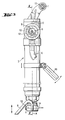
- the feed support device is a hydraulically operated, working cylinder 3 effective on both sides, which one at a first end mounting means 7 which can be easily mounted on the machine tool and on a second one End has a support foot 8.
- the working cylinder 3 is manually on a manually rotatable actuating part 9 operable, designed as a rotary valve Control valve 10 continuously controllable.
- the actuating part 9 is perpendicular to Working cylinder axis A projecting handle that can be rotated around the handle axis B formed, which is only adjustable within an angle of rotation of 180 °.
- the Mounting means 7 is a partially non-rotating bolt connection perpendicular to the drilling axis formed by the eye 16 at the first end of the working cylinder 3
- Machine tool penetrable, one-sided projecting bolt is attached, which is partially broken in its interior by a fluid line 11, which the of the Pressure hose 6 fed into the feed support device and via a Branching point 12 to the working cylinder 3 and to the mounting means 7 fluid branched in introduces the machine tool in a fluid-tight manner.
- the support foot 8 is via a with a cross pin 13 secured, tangentially removable claw 14 at the second end of the working cylinder 3 attached.
- On the working cylinder 3 there is a stirrup handle 15 which can be displaced and pivoted available.
Landscapes
- Engineering & Computer Science (AREA)
- Geology (AREA)
- Mining & Mineral Resources (AREA)
- Life Sciences & Earth Sciences (AREA)
- General Life Sciences & Earth Sciences (AREA)
- Fluid Mechanics (AREA)
- Environmental & Geological Engineering (AREA)
- Physics & Mathematics (AREA)
- Mechanical Engineering (AREA)
- Geochemistry & Mineralogy (AREA)
- Earth Drilling (AREA)
- Finish Polishing, Edge Sharpening, And Grinding By Specific Grinding Devices (AREA)
- Portable Power Tools In General (AREA)
- Drilling And Boring (AREA)
- Percussive Tools And Related Accessories (AREA)
- Drilling And Exploitation, And Mining Machines And Methods (AREA)
Abstract
Description
Claims (10)
- Vorschubstützeinrichtung für eine zumindest teilweise drehende und/oder schlagende, portable Werkzeugmaschine (1), welche als fluidbetriebener Arbeitszylinder (3) ausgebildet ist, der an einem ersten Ende ein an der Werkzeugmaschine (1) montierbares Montagemittel (7) und an einem zweiten Ende einen Stützfuss (8) aufweist, wobei der Arbeitszylinder (3) über ein manuell an einem händisch dreheinstellbaren Betätigungsteil (9) betätigbaren Steuerventil (10) stetig steuerbar ist, dadurch gekennzeichnet, dass das Betätigungsteil (9) als quer zur Arbeitszylinderachse (A) auskragender, um die Griffachse (B) dreheinstellbarer Handgriff ausgebildet ist, welcher innerhalb eines Verdrehwinkels von 180° den gesamten Steuerbereich des Steuerventils (10) steuerbar umfasst.
- Vorschubstützeinrichtung nach Anspruch 1, dadurch gekennzeichnet, dass das Betätigungsteil (9) innerhalb eines Verdrehwinkels von 90° den gesamten Steuerbereich des Steuerventils (10) steuerbar umfasst.
- Vorschubstützeinrichtung nach Anspruch 1 oder 2, dadurch gekennzeichnet, dass das stetig steuerbare Steuerventil (10) als Drehschieber ausgeführt ist.
- Vorschubstützeinrichtung nach einem der vorherigen Ansprüche, dadurch gekennzeichnet, dass der Arbeitszylinder (3) beidseitig wirksam ausgeführt ist.
- Vorschubstützeinrichtung nach einem der vorherigen Ansprüche, dadurch gekennzeichnet, dass das Montagemittel (7) als senkrecht zur Bohrachse teilweise drehfreie Bolzenverbindung ausgebildet ist.
- Vorschubstützeinrichtung nach Anspruch 5, dadurch gekennzeichnet, dass am ersten Ende des Arbeitszylinders (3) ein das Auge an der Werkzeugmaschine (1) durchgreifender, einseitig auskragender Bolzen befestigt ist, welcher optional teilweise in seinem Innern von einer Fluidleitung (11) durchbrochen ist.
- Vorschubstützeinrichtung nach einem der vorherigen Ansprüche, dadurch gekennzeichnet, dass der Arbeitszylinder (3) hydraulisch betätigt ist.
- Vorschubstützeinrichtung nach einem der vorherigen Ansprüche, dadurch gekennzeichnet, dass der Stützfuss (8) über eine einfach monierbare Verlängerung verlängerbar ist.
- Vorschubstützeinrichtung nach einem der vorherigen Ansprüche, dadurch gekennzeichnet, dass der Stützfuss (8) und/oder die Verlängerung durch eine mit einem Querstift (13) gesicherte, tangential abziehbare Kralle (14) montierbar ist.
- Vorschubstützeinrichtung nach einem der vorherigen Ansprüche, dadurch gekennzeichnet, dass am Arbeitszylinder (3) ein versetzbar und oder schwenkbar festlegbarer Bügelgriff (15) vorhanden ist.
Applications Claiming Priority (2)
| Application Number | Priority Date | Filing Date | Title |
|---|---|---|---|
| DE10200309 | 2002-01-07 | ||
| DE10200309A DE10200309A1 (de) | 2002-01-07 | 2002-01-07 | Vorschubstützeinrichtung für eine portable Werkzeugmaschine |
Publications (2)
| Publication Number | Publication Date |
|---|---|
| EP1326001A1 true EP1326001A1 (de) | 2003-07-09 |
| EP1326001B1 EP1326001B1 (de) | 2006-11-22 |
Family
ID=7711597
Family Applications (1)
| Application Number | Title | Priority Date | Filing Date |
|---|---|---|---|
| EP02406106A Expired - Lifetime EP1326001B1 (de) | 2002-01-07 | 2002-12-17 | Vorschubstützeinrichtung für eine portable Werkzeugmaschine |
Country Status (8)
| Country | Link |
|---|---|
| US (1) | US20030164242A1 (de) |
| EP (1) | EP1326001B1 (de) |
| JP (1) | JP2003236712A (de) |
| CN (1) | CN1322221C (de) |
| AU (1) | AU2003200007B2 (de) |
| CA (1) | CA2415057C (de) |
| DE (2) | DE10200309A1 (de) |
| ZA (1) | ZA200300131B (de) |
Cited By (1)
| Publication number | Priority date | Publication date | Assignee | Title |
|---|---|---|---|---|
| AT18241U1 (de) * | 2021-07-09 | 2024-06-15 | Ribo Reinigungs Und Gebaeude Service Ges Mit Beschraenkter Haftung | Vorrichtung zur Reinigung der Oberfläche eines Lamellenwärmetauschers |
Families Citing this family (7)
| Publication number | Priority date | Publication date | Assignee | Title |
|---|---|---|---|---|
| CN102080499A (zh) * | 2011-02-21 | 2011-06-01 | 成涛宇 | 一种自动移动钻孔装置及其施工方法 |
| AU2014246670B2 (en) * | 2013-04-03 | 2017-09-07 | International Mowers Pty Ltd | Powered drill apparatus |
| JP6231782B2 (ja) * | 2013-06-17 | 2017-11-15 | 三橋 満 | 携帯式電動アースオーガー |
| CN106677711B (zh) * | 2016-08-26 | 2018-12-07 | 陕西斯达防爆安全科技股份有限公司 | 一种履带式坑道钻机的机架结构 |
| US10888987B2 (en) | 2017-05-04 | 2021-01-12 | Skitter & Squirt Adventures, Llc | Power tool ski system and method |
| JP6918579B2 (ja) * | 2017-05-29 | 2021-08-11 | 三菱重工機械システム株式会社 | ライニング斫り工法 |
| WO2019000033A1 (en) * | 2017-06-26 | 2019-01-03 | UGT Group Pty Ltd | TRÉPAN AND VALVE ASSEMBLY |
Citations (8)
| Publication number | Priority date | Publication date | Assignee | Title |
|---|---|---|---|---|
| DE74833C (de) | f. J. G. FROMHOLT in Paris, 88 rue Ordener | Drehbohrmaschine mit hydraulischem Vorschub | ||
| DE237604C (de) * | ||||
| FR415939A (fr) * | 1910-04-23 | 1910-10-07 | Maurice Cheronnet | Système perfectionné de perforateur à marteau pneumatique avec avanceur automatique |
| US1151261A (en) | 1914-12-26 | 1915-08-24 | Sullivan Machinery Co | Feed-controlling device. |
| US1464486A (en) | 1914-06-17 | 1923-08-07 | Sullivan Machinery Co | Drilling apparatus |
| FR984495A (fr) * | 1943-10-05 | 1951-07-06 | Cie Ingersoll Rand | Montage-support pour marteau piqueur |
| DE815941C (de) * | 1948-12-03 | 1951-10-08 | Herbert Dr-Ing Jeschke | Pneumatisch verlaengerbare Pendelstuetze fuer Handbohrgeraete |
| US4000873A (en) | 1976-02-12 | 1977-01-04 | The Steel Engineering Company Limited | Mounting for rock drills |
Family Cites Families (15)
| Publication number | Priority date | Publication date | Assignee | Title |
|---|---|---|---|---|
| US1303790A (en) * | 1919-05-13 | Drilling apparatus | ||
| US1146284A (en) * | 1913-01-16 | 1915-07-13 | Owen Dodge | Air and water blowpipe for rock-drilling. |
| US1655265A (en) * | 1927-02-25 | 1928-01-03 | Guiducci Andrea | Jack-hammer rest |
| US1817308A (en) * | 1929-02-20 | 1931-08-04 | Ingersoll Rand Co | Steel support for rock drills |
| US1914430A (en) * | 1930-05-07 | 1933-06-20 | Independent Pneumatic Tool Co | Rock drill mounting |
| US1917335A (en) * | 1932-06-06 | 1933-07-11 | Ingersoll Rand Co | Rock drilling mechanism |
| US2908482A (en) * | 1952-07-16 | 1959-10-13 | Joy Mfg Co | Rock drill |
| US3132703A (en) * | 1956-05-15 | 1964-05-12 | Atlas Copco Ab | Rock drilling mechanism |
| US3189104A (en) * | 1960-09-09 | 1965-06-15 | Atlas Copco Ab | Percussion tools |
| US3203489A (en) * | 1963-07-18 | 1965-08-31 | Thor Power Tool Co | Sinker drill |
| US4024923A (en) * | 1972-11-16 | 1977-05-24 | Kenneth Joseph Broadbent | Rock bolting equipment |
| SE394261B (sv) * | 1973-12-27 | 1977-06-20 | Atlas Copco Ab | Anordning for ljuddempning vid bergborrmaskiner samt bergborrmaskin med sadan anordning |
| SE413748B (sv) * | 1978-10-06 | 1980-06-23 | Atlas Copco Ab | Forfarande for smorjning av en bergborrmaskin och bergborraggregat med en bergborrmaskin smorjd enligt forfarandet |
| FI904366A7 (fi) * | 1989-11-08 | 1991-05-09 | Sulzer Ag | Hydraulinen porauslaite ja menetelmä sen käyttämiseksi |
| US6050345A (en) * | 1997-02-27 | 2000-04-18 | Keyspan Energy | Ergonomic tool with lift assist mechanism |
-
2002
- 2002-01-07 DE DE10200309A patent/DE10200309A1/de not_active Withdrawn
- 2002-12-17 DE DE50208769T patent/DE50208769D1/de not_active Expired - Lifetime
- 2002-12-17 EP EP02406106A patent/EP1326001B1/de not_active Expired - Lifetime
- 2002-12-23 CA CA002415057A patent/CA2415057C/en not_active Expired - Fee Related
- 2002-12-30 CN CNB02160410XA patent/CN1322221C/zh not_active Expired - Fee Related
-
2003
- 2003-01-03 AU AU2003200007A patent/AU2003200007B2/en not_active Ceased
- 2003-01-06 ZA ZA200300131A patent/ZA200300131B/xx unknown
- 2003-01-07 US US10/337,445 patent/US20030164242A1/en not_active Abandoned
- 2003-01-07 JP JP2003000998A patent/JP2003236712A/ja active Pending
Patent Citations (8)
| Publication number | Priority date | Publication date | Assignee | Title |
|---|---|---|---|---|
| DE74833C (de) | f. J. G. FROMHOLT in Paris, 88 rue Ordener | Drehbohrmaschine mit hydraulischem Vorschub | ||
| DE237604C (de) * | ||||
| FR415939A (fr) * | 1910-04-23 | 1910-10-07 | Maurice Cheronnet | Système perfectionné de perforateur à marteau pneumatique avec avanceur automatique |
| US1464486A (en) | 1914-06-17 | 1923-08-07 | Sullivan Machinery Co | Drilling apparatus |
| US1151261A (en) | 1914-12-26 | 1915-08-24 | Sullivan Machinery Co | Feed-controlling device. |
| FR984495A (fr) * | 1943-10-05 | 1951-07-06 | Cie Ingersoll Rand | Montage-support pour marteau piqueur |
| DE815941C (de) * | 1948-12-03 | 1951-10-08 | Herbert Dr-Ing Jeschke | Pneumatisch verlaengerbare Pendelstuetze fuer Handbohrgeraete |
| US4000873A (en) | 1976-02-12 | 1977-01-04 | The Steel Engineering Company Limited | Mounting for rock drills |
Cited By (1)
| Publication number | Priority date | Publication date | Assignee | Title |
|---|---|---|---|---|
| AT18241U1 (de) * | 2021-07-09 | 2024-06-15 | Ribo Reinigungs Und Gebaeude Service Ges Mit Beschraenkter Haftung | Vorrichtung zur Reinigung der Oberfläche eines Lamellenwärmetauschers |
Also Published As
| Publication number | Publication date |
|---|---|
| ZA200300131B (en) | 2003-07-23 |
| JP2003236712A (ja) | 2003-08-26 |
| CN1432716A (zh) | 2003-07-30 |
| CA2415057A1 (en) | 2003-07-07 |
| DE10200309A1 (de) | 2003-07-17 |
| EP1326001B1 (de) | 2006-11-22 |
| US20030164242A1 (en) | 2003-09-04 |
| AU2003200007B2 (en) | 2008-12-18 |
| CN1322221C (zh) | 2007-06-20 |
| DE50208769D1 (de) | 2007-01-04 |
| CA2415057C (en) | 2007-11-20 |
Similar Documents
| Publication | Publication Date | Title |
|---|---|---|
| DE2306397C3 (de) | Vorrichtung zum bergmännischen drehenden oder drehschlagenden Bohren | |
| DE60206276T2 (de) | Lenkbare drehbohrmeisseleinrichtung mit pilotbohrer | |
| EP2085566B1 (de) | Bohranlage | |
| DE60125160T2 (de) | Vorrichtung und verfahren zum richtbohren | |
| DE10115116A1 (de) | Staubabsaugung für ein Handwerkzeuggerät | |
| EP0985082B1 (de) | Tunnelbohrmaschine | |
| EP2322724B1 (de) | Unterwasserbohranordnung und Verfahren zum Einbringen eines rohrförmigen Gründungselements in den Gewässergrund | |
| CH693873A5 (de) | Absaugeinrichtung fuer eine Handwerkzeugmaschine, insbesondere einen Bohrhammer. | |
| DE69119402T2 (de) | Im bohrloch zu gebrauchendes bohrwerkzeug zum bohren vor einer verrohrung | |
| DE10200309A1 (de) | Vorschubstützeinrichtung für eine portable Werkzeugmaschine | |
| EP0886034B1 (de) | Bohrvorrichtung | |
| EP0334807B1 (de) | Hinterschnitt-Bohrvorrichtung | |
| DE19858519C2 (de) | Pneumatisch umsteuerbares Rammbohrgerät | |
| DE2812358A1 (de) | Verfahren zur steuerung der bewegungsumkehr von einrichtungen zur bildung von bohrungen im boden und einrichtung zur durchfuehrung des verfahrens | |
| US7462004B2 (en) | Drill fixture | |
| DE2824441A1 (de) | Erdbohrer | |
| DE19501663A1 (de) | Höhenverstellbarer Werkzeughalter | |
| EP0906811B1 (de) | Bohrhammer | |
| DE202018106384U1 (de) | Mobile Bohrhilfsvorrichung | |
| EP0510416A2 (de) | Schlagwerk für ein Bohrgestänge | |
| DE29604902U1 (de) | Bohrvorrichtung | |
| EP2192064B1 (de) | Vorrichtung zum Materialtransport | |
| DE9309277U1 (de) | Sägevorrichtung, insbesondere zum Ausschneiden eines kreisförmigen Mauerwerkausschnittes | |
| DE10354726B3 (de) | Bohrvorrichtung für Kernbohrungen | |
| DE19831009C2 (de) | Bohrvorrichtung |
Legal Events
| Date | Code | Title | Description |
|---|---|---|---|
| PUAI | Public reference made under article 153(3) epc to a published international application that has entered the european phase |
Free format text: ORIGINAL CODE: 0009012 |
|
| AK | Designated contracting states |
Designated state(s): AT BE BG CH CY CZ DE DK EE ES FI FR GB GR IE IT LI LU MC NL PT SE SI SK TR |
|
| AX | Request for extension of the european patent |
Extension state: AL LT LV MK RO |
|
| 17P | Request for examination filed |
Effective date: 20040109 |
|
| AKX | Designation fees paid |
Designated state(s): CH DE FR GB LI SE |
|
| 17Q | First examination report despatched |
Effective date: 20041015 |
|
| GRAP | Despatch of communication of intention to grant a patent |
Free format text: ORIGINAL CODE: EPIDOSNIGR1 |
|
| GRAS | Grant fee paid |
Free format text: ORIGINAL CODE: EPIDOSNIGR3 |
|
| GRAA | (expected) grant |
Free format text: ORIGINAL CODE: 0009210 |
|
| AK | Designated contracting states |
Kind code of ref document: B1 Designated state(s): CH DE FR GB LI SE |
|
| REG | Reference to a national code |
Ref country code: GB Ref legal event code: FG4D Free format text: NOT ENGLISH |
|
| REG | Reference to a national code |
Ref country code: CH Ref legal event code: EP |
|
| REF | Corresponds to: |
Ref document number: 50208769 Country of ref document: DE Date of ref document: 20070104 Kind code of ref document: P |
|
| REG | Reference to a national code |
Ref country code: SE Ref legal event code: TRGR |
|
| ET | Fr: translation filed | ||
| PLBE | No opposition filed within time limit |
Free format text: ORIGINAL CODE: 0009261 |
|
| STAA | Information on the status of an ep patent application or granted ep patent |
Free format text: STATUS: NO OPPOSITION FILED WITHIN TIME LIMIT |
|
| 26N | No opposition filed |
Effective date: 20070823 |
|
| REG | Reference to a national code |
Ref country code: FR Ref legal event code: PLFP Year of fee payment: 14 |
|
| PGFP | Annual fee paid to national office [announced via postgrant information from national office to epo] |
Ref country code: DE Payment date: 20151208 Year of fee payment: 14 Ref country code: GB Payment date: 20151216 Year of fee payment: 14 Ref country code: CH Payment date: 20151211 Year of fee payment: 14 |
|
| PGFP | Annual fee paid to national office [announced via postgrant information from national office to epo] |
Ref country code: FR Payment date: 20151110 Year of fee payment: 14 Ref country code: SE Payment date: 20151211 Year of fee payment: 14 |
|
| REG | Reference to a national code |
Ref country code: DE Ref legal event code: R119 Ref document number: 50208769 Country of ref document: DE |
|
| REG | Reference to a national code |
Ref country code: CH Ref legal event code: PL |
|
| REG | Reference to a national code |
Ref country code: SE Ref legal event code: EUG |
|
| GBPC | Gb: european patent ceased through non-payment of renewal fee |
Effective date: 20161217 |
|
| PG25 | Lapsed in a contracting state [announced via postgrant information from national office to epo] |
Ref country code: SE Free format text: LAPSE BECAUSE OF NON-PAYMENT OF DUE FEES Effective date: 20161218 |
|
| REG | Reference to a national code |
Ref country code: FR Ref legal event code: ST Effective date: 20170831 |
|
| PG25 | Lapsed in a contracting state [announced via postgrant information from national office to epo] |
Ref country code: CH Free format text: LAPSE BECAUSE OF NON-PAYMENT OF DUE FEES Effective date: 20161231 Ref country code: FR Free format text: LAPSE BECAUSE OF NON-PAYMENT OF DUE FEES Effective date: 20170102 Ref country code: LI Free format text: LAPSE BECAUSE OF NON-PAYMENT OF DUE FEES Effective date: 20161231 |
|
| PG25 | Lapsed in a contracting state [announced via postgrant information from national office to epo] |
Ref country code: GB Free format text: LAPSE BECAUSE OF NON-PAYMENT OF DUE FEES Effective date: 20161217 Ref country code: DE Free format text: LAPSE BECAUSE OF NON-PAYMENT OF DUE FEES Effective date: 20170701 |