EP1325684A1 - Vorrichtung zum Perforieren von stabförmigen Gegenstände, insbesondere der Tabak verarbeitenden Industrie - Google Patents
Vorrichtung zum Perforieren von stabförmigen Gegenstände, insbesondere der Tabak verarbeitenden Industrie Download PDFInfo
- Publication number
- EP1325684A1 EP1325684A1 EP02028601A EP02028601A EP1325684A1 EP 1325684 A1 EP1325684 A1 EP 1325684A1 EP 02028601 A EP02028601 A EP 02028601A EP 02028601 A EP02028601 A EP 02028601A EP 1325684 A1 EP1325684 A1 EP 1325684A1
- Authority
- EP
- European Patent Office
- Prior art keywords
- rotating body
- curved
- section
- axis
- rotation
- Prior art date
- Legal status (The legal status is an assumption and is not a legal conclusion. Google has not performed a legal analysis and makes no representation as to the accuracy of the status listed.)
- Granted
Links
- 241000208125 Nicotiana Species 0.000 title claims description 8
- 235000002637 Nicotiana tabacum Nutrition 0.000 title claims description 8
- 239000000463 material Substances 0.000 claims description 17
- 230000035699 permeability Effects 0.000 claims description 3
- 238000012545 processing Methods 0.000 claims description 3
- 235000019504 cigarettes Nutrition 0.000 abstract description 80
- 230000003287 optical effect Effects 0.000 description 9
- 238000005096 rolling process Methods 0.000 description 9
- 230000000391 smoking effect Effects 0.000 description 6
- 238000012546 transfer Methods 0.000 description 6
- 238000004519 manufacturing process Methods 0.000 description 5
- 230000002093 peripheral effect Effects 0.000 description 5
- 238000001035 drying Methods 0.000 description 4
- 239000011257 shell material Substances 0.000 description 4
- 238000005520 cutting process Methods 0.000 description 3
- 238000013461 design Methods 0.000 description 2
- 230000000694 effects Effects 0.000 description 2
- 238000012986 modification Methods 0.000 description 2
- 230000004048 modification Effects 0.000 description 2
- 230000005855 radiation Effects 0.000 description 2
- SNICXCGAKADSCV-JTQLQIEISA-N (-)-Nicotine Chemical compound CN1CCC[C@H]1C1=CC=CN=C1 SNICXCGAKADSCV-JTQLQIEISA-N 0.000 description 1
- 238000004026 adhesive bonding Methods 0.000 description 1
- 230000015572 biosynthetic process Effects 0.000 description 1
- 238000010276 construction Methods 0.000 description 1
- 230000002950 deficient Effects 0.000 description 1
- 238000000034 method Methods 0.000 description 1
- 229960002715 nicotine Drugs 0.000 description 1
- SNICXCGAKADSCV-UHFFFAOYSA-N nicotine Natural products CN1CCCC1C1=CC=CN=C1 SNICXCGAKADSCV-UHFFFAOYSA-N 0.000 description 1
- 238000001208 nuclear magnetic resonance pulse sequence Methods 0.000 description 1
- 238000000926 separation method Methods 0.000 description 1
- 239000000779 smoke Substances 0.000 description 1
- 238000012360 testing method Methods 0.000 description 1
Images


Classifications
-
- A—HUMAN NECESSITIES
- A24—TOBACCO; CIGARS; CIGARETTES; SIMULATED SMOKING DEVICES; SMOKERS' REQUISITES
- A24C—MACHINES FOR MAKING CIGARS OR CIGARETTES
- A24C5/00—Making cigarettes; Making tipping materials for, or attaching filters or mouthpieces to, cigars or cigarettes
- A24C5/60—Final treatment of cigarettes, e.g. marking, printing, branding, decorating
- A24C5/606—Perforating cigarettes
-
- B—PERFORMING OPERATIONS; TRANSPORTING
- B23—MACHINE TOOLS; METAL-WORKING NOT OTHERWISE PROVIDED FOR
- B23K—SOLDERING OR UNSOLDERING; WELDING; CLADDING OR PLATING BY SOLDERING OR WELDING; CUTTING BY APPLYING HEAT LOCALLY, e.g. FLAME CUTTING; WORKING BY LASER BEAM
- B23K26/00—Working by laser beam, e.g. welding, cutting or boring
- B23K26/08—Devices involving relative movement between laser beam and workpiece
- B23K26/0823—Devices involving rotation of the workpiece
Definitions
- the invention relates to a device for producing zones of desired Air permeability in the shell material of rod-shaped objects, in particular the Tobacco processing industry, with a rotating around an axis of rotation mounted rotating body with at least one reflective surface for reflecting a high-energy beam during the rotation of the rotating body for generation of perforation zones on the wrapping material, the reflection surface has at least one section which is designed such that when rotating of the rotating body the beam reflected by this section travels.
- Rod-shaped smoking articles are usually roller drums and the like. used. These means of transport convey the cigarettes across the axis through the point of impact of the beam through.
- To perforation not only in one place on the To achieve peripheral surface of the cigarette and thus in the wrapping material, but in order to maintain the perforation over at least part of the circumference, the Cigarette, mostly while it is being transported axially by the means of transport Rolled with the help of rolling stock, the cigarette mostly from that of the means of transport capture opposite side.
- the above-mentioned rotating body is provided, which is a The axis of rotation is mounted in a rotating manner.
- the rotating body is usually turned through a drive device provided for this purpose.
- the rotating body has one Reflection surface, which is a high-energy generated by a beam source Beam, usually a laser beam, during rotation of the rotating body reflected.
- the reflected beam is focused on the envelope material to there then create the desired perforation zones.
- the reflective surface serves as a mirror and is designed so that when the rotating body rotates the reflected beam travels and thus its point of impact describes a path. In this way it is possible to transport the beam during transverse axial to track the cigarette accordingly.
- the light source is the high energy Beam is usually modulated, particularly in a pulsed form, generated in the Perforation zones to make discrete holes in one or more rows.
- the pulse sequences By setting the pulse sequences, many can be done in this way different perforation patterns and in particular a different one Realize division of the respective row of holes.
- EP 1 018 392 A2 describes a perforation device for producing Openings in a peripheral surface, in particular a cigarette.
- This well-known Perforation device has a light source for generating at least one high energy light beam, with the help of which the perforations in the Wrapping material of a cigarette can be introduced, a tracking agent for tracking of the light beam, an effective zone that can be generated by the tracking means, within of which the light beam for introducing the perforations onto one through the Action zone moving cigarette acts, rolling means to produce a Self-rotating movement of the cigarettes about their longitudinal axis while they are move through the effective zone to the peripheral surface of the light beam suspend, and means of transportation to carry the cigarettes through the Effective zone.
- the tracking agent consists of at least one Swivel mirror.
- the light beam Before reaching the effective zone, the light beam is also still passed through a light refraction means so that when the Light beam this essentially everywhere within the effective zone on the Peripheral surface remains focused. Accordingly, this known device is in the Position, during the cross-axial transport of the cigarette the beam adjust accordingly in order to distribute perforations in the circumferential direction produce.
- DE 40 38 928 A1 discloses a device for perforating cigarettes, which has a rotating body with a stepped end face.
- the stages or step-shaped sections of the end face are arranged parallel to one another and provide deflecting mirrors for a laser beam for perforating cigarettes
- the at an angle to the axis of rotation of the rotating body on the end face incident laser beam is alternated by the steps of the face distracted different ways that are offset parallel to each other.
- a number of perforations corresponding to the number of steps in the end face of the rotating body.
- this is well known Device only suitable for perforations in the wrapping material of a cigarette to generate, which are spaced apart in the axial direction of the cigarette.
- this known device is not able to transverse axial transport of the cigarette or other rod-shaped Object to track the beam accordingly, in the circumferential direction spread perforations to create.
- DE 195 11 393 A1 describes a device for perforating Cigarette paper webs known, which also has a rotating body.
- the rotating body of this known device consists of a polygon mirror, through which a laser beam rotates cyclically through a certain one Angular range is pivoted.
- In the beam path of this Deflected laser beam is a series of side by side lying optical elements arranged, each of which optical element the laser beam to a specific location of the enveloping material to form Perforations focused. This way, according to the number of Perforation zones lying side by side in the optical elements Cigarette paper web generated.
- This object is achieved in that the device at the beginning mentioned type of section of the reflective surface a curved or has a curved course.
- the invention can be particularly also for the production of perforation zones in the circumferential direction on the Wrapping material from rod-shaped objects such as cigarettes use if they perform a transverse axial movement at the same time.
- the invention is used in particular for the production of perforation zones in Circumferential direction on the wrapping material of itself simultaneously axially Moving rod-shaped objects should be used Arrangement must be made so that the beam during a work cycle is tracked along a focus path that corresponds to the length of the circumference of the corresponds to the rod-shaped object, i.e. the rotating body around the Rotation angle between the start point and end point of the curved Reflected surface section rotated and at the same time the one to be irradiated rod-shaped object is rolled transversely through 360 °.
- the curved section of the reflection surface is expedient stripe-shaped.
- the curved section of the reflection surface helical.
- the Screw axis extend parallel to the axis of rotation of the rotating body and preferably coincide with this. Furthermore, the screw axis should be extend parallel to the direction of incidence of the beam and the slope of the Helical shape of the reflecting surface section must be constant.
- the rotating body should have the shape of a cylinder, the Cylinder axis is the axis of rotation and around its jacket the Reflective surface is formed.
- the reflective surface should be angled to the end face of the rotating body be aligned.
- the reflection surface can be a single curved or curved section or a plurality of continuous have connected such sections or from such be educated.
- the reflection surface can also be one have certain number of curved sections that are mutually are arranged separately. It can be curved between each Sections of jumps or discontinuities may be present. Furthermore, the individual curved sections of the reflection surface in the direction of the circumference of the rotating body to be spaced apart, preferably the Initial areas of the curved sections on a first level and the End regions of the curved sections can lie on a second plane, wherein the two planes are angled, preferably substantially transverse to Axis of rotation of the rotating body, and parallel to each other and from each other are spaced. The curved sections of the Reflecting surface over the circumference of the rotating body essentially be evenly distributed.
- the reflection surface can also be used several partial curves or partial surfaces can be executed, whereby after one defined rotation angle of the rotating body about its axis of rotation with continued Rotation an automatic return of the incident beam from the end point of the previous reflection surface section or the previous one Partial area to the starting point of the next one Reflection surface section or the next partial area takes place.
- the Rotation angle of the rotating body between the start and end point of the curved or curved section thus corresponds to that during the Rotation of the rotating body around this focus path to be mapped of the beam.
- the rotary body should rotate around this angle of rotation during a Work cycle be rotated.
- the curved sections should preferably have a shape, shape, Direction and / or slope essentially match, so that the Reflection surface can have several similar partial surfaces.
- the or each curved section of the Reflecting surface has an incline of approximately 45 ° with respect to the axis of rotation of the Have rotating body. Such a pitch angle has been particularly effective exposed.
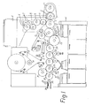
- the filter attachment machine according to FIG. 1 is known per se and is used in The following for general understanding only briefly regarding structure and Effectiveness described.
- An inlet drum 1 transfers the to a cigarette manufacturing machine produced cigarettes on two relay drums 2, which the staggered Unstuck the supplied cigarettes and in rows of two with one Intermediate space between the cigarettes to an assembly drum 3 submit.
- the filter rods pass from a magazine 4 onto a cutting drum 6, are made of two circular knives 7 to filter plugs twice the length of use cut, staggered on a relay drum 8, from a sliding drum 9 aligned in a row of plugs and one Accelerator drum 11 in the spaces between the rows of cigarettes on the Compilation drum 3 filed.
- the cigarette-filter-cigarette groups formed in this way are pushed together, so that they are axially close together. Then they are from a transfer drum 12 taken over.
- a covering paper strip 13 is from a base paper bobbin 14 by means of a feed arrangement in the form of a Pull-off roller 16 is pulled off.
- the covering paper strip 13 becomes a sharp one Edge-containing pre-crusher 17 is deflected around by a gluing device 18 glued and cut on a covering roller 19 by a knife drum 21.
- the Cut topping papers are attached to the cigarette filter groups on the Transfer drum 12 attached and on a roller drum 22 by means of a Rollhand 23 rolled around the cigarette filter groups.
- the double filter cigarette groups thus manufactured and now manufactured via a drying drum 24 and fed to a cutting drum 26 by cutting through the center of the filter plug into single filter cigarettes assembled, whereby defective filter cigarettes are ejected at the same time.
- One with a transfer drum 27 and a collecting drum 28 cooperating turning device 29 turns a row of filter cigarettes and transfers them simultaneously into the via the transfer drum 27 and Collection drum 28 through unturned filter cigarette row.
- the filter cigarettes reach an ejection drum 32 on which the head of the filter cigarettes is also scanned before the ejection process.
- a co-operating with a brake drum 33 lay drum 34 Filter cigarettes on a deposit belt 36.
- the filter attachment machine is a laser head 37 in the area of a cross conveyor, in the present case of the drying drum 24 or the collecting drum 28, assigned.
- the laser head 37 is part of an optical perforation device, such as they further below with reference to Figures 3 and 4 in two different preferred Descriptions is described, and serves as a radiation source for generation and Delivery of a laser beam.
- An essential part of the optical Perforation device forms a cylindrical rotating mirror 44, as shown in FIG. 2 is shown.
- the cylindrical rotating mirror 44 is about its cylinder axis 44a rotatably mounted.
- the rotating mirror 44 is not set in rotation by one shown drive device. The rotates during operation Rotating mirror 44 at constant speed.
- the laser head 37 (FIG.
- the formation and the course of a can be seen particularly well in FIG striped reflection section 46.
- the striped reflection section 46 forms a helical or partially helical mirror surface, wherein the screw axis with the cylinder or rotation axis 44a of the rotating mirror 44 coincides. Furthermore, in the illustrated embodiment strip-shaped reflection surface 46 perpendicular to the surface of the jacket cylindrical body of the rotating mirror 44 aligned.
- the - expediently constant - helical slope of the The result is strip-shaped reflection section 46 or the mirror surface, that when the rotating mirror 44 rotates in the direction of rotation of the arrow B reflected beam 48 from the beginning 46a to the end 46b of the stripe Reflection section 46 transverse to its beam axis over a certain Distance moves.
- This distance corresponds to a simple circumferential length a cigarette, the wrapping material or topping paper through the jet should be perforated accordingly.
- the slope of the strip is Reflection section 46 45 ° and the angle of reflection between incident Laser beam 38 and reflected beam 48 90 °. Basically, too other angular arrangements are conceivable.
- the rotating mirror 44 can be made with a single strip Reflection section 46 of the type discussed with reference to FIG. 2 or also with a plurality of such strip-shaped reflection sections 46 can be implemented.
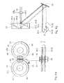
- Figure 3a is a first preferred embodiment of the optical Perforation device shown.
- the one emerging from the laser head 37 When viewed in cross section, laser beam 38 has approximately a circular shape; this is in FIG. 3b schematically shows a cross section through the laser beam 38 along the dash-dotted line b-b of Figure 3a.
- the Laser head 37 downstream lens optics 39 is the cross section circular laser beam 38 in the embodiment of Figure 3 in a so-called Surface jet converted, which has approximately the shape of a line in cross section; this is indicated in FIG.
- FIG. 3c which shows the cross section through the laser beam 38 at a point along the dash-dotted line c-c of Figure 3a behind the Lens optics 39 shows schematically.
- the embodiment shown in Figure 3 optical perforation device has a deflecting head Housing 40, through the opening 42 facing the laser head 37 of the laser beam 38 converted by the lens optics 39 enters the housing 40.
- the laser beam 38 strikes the one arranged there cylindrical rotating mirror 44, which has already been described in detail with reference to FIG. 2 has been described.
- the lens optics 39 shown discretely in FIG. 3 it is also conceivable to design the laser head 37 such that a cross-section is already there line-shaped laser beam is generated.
- the Lens optics 39 can be arranged in the laser head 37.
- the one on the strip-shaped reflection sections 46 of the rotating mirror 44 reflected beam 48 is passed through a partial cylindrical lens 50 which with its Axis is arranged transversely to the beam path of the reflected beam 48.
- FIG. 3d shows the partial cylinder lens 50 in cross section.
- the Partial cylinder lens 50 becomes the beam 48 with a cross-section in a cross-section converging beam converted as the focused beam 52 on the Extent of a cigarette 60 already provided with covering paper is directed where the focused beam 52 at its point of impact on the tipping paper Perforation zone extending circumferentially.
- a rotatably mounted roller drum 70 is provided, which is only shown in FIG. 3a is shown in sections.
- This roller drum 70 can be the Drying drum 24 or the collecting drum 28 of the one shown in FIG. 1 Act filter attachment machine.
- the roller drum 70 has along its circumference a series of elevations 72 in an equidistant arrangement, the Area between two elevations 72 as a so-called rolling section 74 is trained.
- Each rolling section 74 is thus of a first flank 76 one elevation 72 and from a second flank 77 of the other elevation 72 limited and has, in longitudinal section or in the direction of rotation A of the roller drum 70 considered the shape of a tub.
- Each roll section 74 takes a cigarette on, of which in Figure 3a only for reasons of clarity The cigarette shown on the left is identified by the reference symbol "60".
- the area of the irradiation by the focused beam 52 becomes the cigarette 60 in the rolling section 74 along the circumferential or rotational direction A using a Counter roll tape 78 rolled, which touches the cigarette 60.
- At the Counter roll belt 78 is an endless belt, which is two parallel Rolls 80, 81 revolves.
- the rolling section 74 forms a rolling surface and that Counter roll belt 78 a counter roll surface for the transverse axial transport of the Cigarettes 60, the transverse axial transport direction of the direction of rotation A equivalent.
- the counter-roller belt 24 brakes in the illustrated embodiment cigarette 60 lying on the leading first flank 76, so that this rolls back over the roller section 74 relative to the roller drum 70 so that it finally comes to rest on the trailing second flank 77. So is according to the embodiment shown in Figure 3a, the peripheral speed the roller drum 70 higher than the conveying speed of the Counter roll belt 78 selected.
- the cigarette 60 is 360 ° around its The longitudinal axis rotates as long as it is irradiated by the focused beam 52.
- the Form lens optics 39 so that the laser head 37 generates, in Cross section circular laser beam 38 in a punctiform in cross section Laser beam is converted, which then eliminates the partial cylinder lens 50 can.
- the Laser head 37 can be designed so that there is already a cross section point laser beam is generated.
- these modifications require modification a relatively high design effort.
- the optical perforation device may be preferred in a second Be designed so that the generated by the laser head 37 Laser beam 38 is converted into a converging beam.
- Such Execution is with its essential components, through which it differs from the 3, schematically in FIG. 4 shown.
- This second preferred embodiment has a first rotating mirror 44 a second rotating mirror 45.
- the representation of Figure 4a compared to the representations of Figures 2 and 3a rotated by 90 ° and run the axes of rotation 44a and 45a of the rotating mirrors 44 and 45 and the beam path of the incident laser beam 38 perpendicular to the image plane of FIG. 4a, while Figure 4b is a side view of the second embodiment with respect to the Direction of view corresponding to the representations of Figures 2 and 3a shows.
- the second embodiment shown in Figure 4 also differs from that first embodiment according to FIG. 3 in that instead of the lens optics 39 from FIG. 3 shows a simple converging lens arrangement 39a between the (in FIG not shown) arranged laser head 37 and the rotating mirrors 44 and 45 is. Because of the arrangement of two rotating mirrors 44 and 45, the Laser head 37 and the converging lens arrangement 39a can be designed such that two laser beams 38 running parallel to one another are generated, as in FIG 4a shows schematically.
- the converging lens arrangement 39a usually designed to consist of two side by side There are lens sections, as is also indicated in FIG. 4a.
- the focal length the converging lens arrangement 39a is dimensioned such that the focal point in the entire beam path is clearly behind the rotating mirror 44, namely a place where the converging laser beam is already on the perimeter of one Base paper provided cigarette 40 hits.
- the laser beam 38 is thus converged into one by the converging lens arrangement 39a converging laser beam converted.
- this second embodiment also conceivable to already provide the laser head 37 in such a way that it creates a converging laser beam.
- the second embodiment according to FIG. 4 of course also in the same way as the first embodiment according to the figure 3 can be provided with a housing forming a deflection head, which but is not shown in Figure 4.
- the two rotating mirrors 44, 45 are in the second exemplary embodiment shown 4a mirror-symmetrical to each other and arranged, the laser beams 38 incident perpendicular to the image plane of FIG. 4a always at the opposite strip-shaped reflection sections 46 be reflected so that the reflected beam forms a double beam which consists of the two reflected rays 48 and 49.
- These two rays 48 and 49 are reflected on deflecting mirrors 58, where they are then focused Beams 52, 54 emerge in the direction of the cigarette 60 to be irradiated, such as Figure 4 and 5 can be seen.
- the optical perforation device 4 is a cigarette 60 to be perforated Double cigarette, which is explained in more detail below.
- the reference symbol 60-I is located in the illustration of FIG. 4 at the beginning of a the focus path of the focused beams 52, 54 corresponding transport path with a distance C, while that shown in dashed lines Double cigarette with the reference number 60-II at the end of this transport route is shown.
- the transverse axial movement of the cigarette 60 during the Perforation takes place at an angle to in the illustrated embodiment Beam path of the focused beams 52, 54 instead, as can be clearly seen in FIG. 4b leaves.
- each rotating mirror 44, 45 with four strip-shaped Reflecting sections 46, each of which is strip-shaped Reflection section 46 extends over a quarter circle.
- the four reflection sections 46 of each rotating mirror 44, 45 form sub-curves with respect to shape, course, direction and slope to match.
- the initial areas 46a lie in the Reflection sections 46 in a first imaginary plane, which are adjacent to the runs an end face of the rotating body or coincides with this, and the End regions 46b (FIG. 2) of the reflection sections 46 in a second imaginary plane that runs adjacent to the opposite end face or coincides with this, those first and second thought Levels are perpendicular to the axis of rotation 44a or 45a of the respective Rotate mirror 44 and 45 extend.
- each rotating mirror 44, 45 is rotated through 90 °, while the Roll the cigarette to be perforated by executing a 360 ° rotation and thus transported by the distance C in the transverse axial direction according to arrow A. becomes.
- a subsequent cigarette is perforated, while each rotating mirror 44, 45 is rotated by a further 90 °. Therefore corresponds to the angle of rotation of the rotating mirrors 44, 45 per work cycle (90 ° in illustrated embodiment) the focus path to be mapped during this time of the focused beam 52 with the distance C.
- the beam diameter of the incident laser beam 38 is determined by the Converging lens assembly 39a to a smaller diameter than that of Laser head 37 generated raw beam diameter pre-focused to the usable To optimize laser usage time or the usable laser beam path per work cycle.
- this is discussed embodiment of a so-called double-jet version acts to perforate double cigarettes.
- double cigarettes during manufacture by placing between two axially aligned tobacco strands a double length filter section is used and this group of tobacco rods and filter section with a glued Covering sheets is connected.
- the double cigarette When the perforations are placed in the envelope of a double cigarette the double cigarette will be on a drum, in the case of the one shown in FIG shown filter attachment machine on the drying drum 24 or Collecting drum 28, reflected in the focus area of the two and focused rays 52, 54 conveyed (see Figure 4) that two of each other spaced, extending in the circumferential direction of the double cigarette 60 annular perforation traces or rows of holes 62 and 64 arise, of which one perforation track 62 in the filter section of one cigarette and the other Perforation trace 64 is formed in the filter section of the other cigarette, such as Figure 5 shows schematically.
- the helical course of the strip-shaped reflection sections 46 Rotation of the rotating mirror 44 or 45 produces the same effect as one inclined plane, which is shifted in the direction of its normal, but with the difference that a rotating rotating mirror with a helical Mirror surface requires a much simpler kinematics.
- FIG. 4b An illustration of the mode of action is shown in FIG. 4b, in addition to the course of the helical mirror surface two strip-shaped reflection sections 46 the associated slope as dashed straight line is shown.
- the dashed straight line also indicates also the course of the helical mirror surface of the associated one strip-shaped reflection section 46 unwound as an inclined Reflective surface. It can be clearly seen in FIG.
- reflection mirrors 58 already mentioned are shown in FIG. Alternatively, however, it is also conceivable, provided the space conditions allow it Omit reflection mirror 58 in the second embodiment according to FIG. 4 and focus the reflected rays 48, 49 directly onto the cigarette 60. Conversely, the first embodiment according to FIG Reflection mirrors can be equipped, provided there is space require.
Landscapes
- Physics & Mathematics (AREA)
- Optics & Photonics (AREA)
- Engineering & Computer Science (AREA)
- Plasma & Fusion (AREA)
- Mechanical Engineering (AREA)
- Manufacturing Of Cigar And Cigarette Tobacco (AREA)
- Physical Vapour Deposition (AREA)
Abstract
Description
- Figur 1
- eine schematische Darstellung einer Filteransetzmaschine der Anmelderin;
- Figur 2
- in schematischer Seitenansicht die Anordnung eines Drehspiegels, der Teil einer in der Filteransetzmaschine von Figur 1 verwendeten Perforationsvorrichtung ist;
- Figur 3
- eine schematische Darstellung einer ersten bevorzugten Ausführung einer in der Filteransetzmaschine von Figur 1 verwendeten Perforationsvorrichtung (a), Querschnittsansichten des Strahlenganges an zwei verschiedenen Stellen der Vorrichtung (b und c) sowie eine Querschnittsansicht einer in dieser Vorrichtung verwendeten Teilzylinderlinse;
- Figur 4
- den wesentlichen Teil einer zweiten bevorzugten Ausführung einer in der Filteransetzmaschine von Figur 1 verwendeten Perforationsvorrichtung in schematischer Stirnansicht (a) und in schematischer Seitenansicht (b); und
- Figur 5
- eine ausschnittsweise Vergrößerung des Hüllmaterialabschnitts mit darauf erzeugten Perforationsreihen.
Claims (13)
- Vorrichtung zum Herstellen von Zonen (62, 64) gewünschter Luftdurchlässigkeit im Hüllmaterial stabförmiger Gegenstände (60) insbesondere der Tabak verarbeitenden Industrie, mit einem um eine Drehachse (44a) drehbar gelagerten Drehkörper (44) mit mindestens einer Reflexionsfläche (46) zur Reflexion eines energiereichen Strahls (38) während der Rotation des Drehkörpers (44) zur Erzeugung von Perforationszonen (62) auf dem Hüllmaterial, wobei die Reflexionsfläche (46) mindestens einen Abschnitt (46) aufweist, der so ausgebildet ist, dass bei Rotation des Drehkörpers (44) der von diesem Abschnitt (44) reflektierte Strahl (48) wandert,
dadurch gekennzeichnet, dass der Abschnitt (46) einen gebogenen oder gekrümmten Verlauf hat. - Vorrichtung nach Anspruch 1,
dadurch gekennzeichnet, dass der gekrümmte Abschnitt (46) der Reflexionsfläche streifenförmig ausgebildet ist. - Vorrichtung nach Anspruch 1 oder 2,
dadurch gekennzeichnet, dass der gekrümmte Abschnitt (46) der Reflexionsfläche schraubenförmig verläuft. - Vorrichtung nach Anspruch 3,
dadurch gekennzeichnet, dass die Schraubenachse des gekrümmten Abschnitts (46) der Reflexionsfläche sich parallel zur Drehachse (44a) des Drehkörpers (44) erstreckt oder mit dieser zusammenfällt. - Vorrichtung nach Anspruch 3 oder 4,
dadurch gekennzeichnet, dass sich die Schraubenachse des gekrümmten Abschnitts (46) der Reflexionsfläche parallel zur Einfallsrichtung des Strahls (38) erstreckt. - Vorrichtung nach mindestens einem der vorangegangenen Ansprüche,
dadurch gekennzeichnet, dass der Drehkörper (44) die Form eines Zylinders hat, dessen Zylinderachse die Drehachse (44a) ist und um dessen Mantel herum die Reflexionsfläche (46) angeordnet ist. - Vorrichtung nach mindestens einem der vorangegangenen Ansprüche,
dadurch gekennzeichnet, dass die Reflexionsfläche (46) winklig zur Oberfläche des Drehkörpers (44) ausgerichtet ist. - Vorrichtung nach mindestens einem der vorangegangenen Ansprüche,
dadurch gekennzeichnet, dass die Reflexionsfläche eine bestimmte Anzahl von gekrümmten Abschnitten (46) aufweist, die voneinander getrennt angeordnet sind. - Vorrichtung nach Anspruch 8,
dadurch gekennzeichnet, dass zwischen den einzelnen gekrümmten Abschnitten (46) Sprünge oder Unstetigkeiten vorhanden sind. - Vorrichtung nach Anspruch 9,
dadurch gekennzeichnet, dass die Anfangsbereiche (46a) der gekrümmten Abschnitte (46) in einer ersten Ebene und die Endbereiche (46b) der gekrümmten Abschnitte (46) in einer zweiten Ebene liegen, wobei die beiden Ebenen parallel zueinander, vorzugsweise im wesentlichen quer zur Drehachse (44a) des Drehkörpers (44), verlaufen und voneinander beabstandet sind. - Vorrichtung nach Anspruch 10,
dadurch gekennzeichnet, dass die gekrümmten Abschnitte (46) der Reflexionsfläche über dem Umfang des Drehkörpers (44) im wesentlichen gleichmäßig verteilt angeordnet sind. - Vorrichtung nach mindestens einem der Ansprüche 8 bis 11,
dadurch gekennzeichnet, dass die gekrümmten Abschnitte (46) hinsichtlich ihrer Form, Verlauf, Richtung und/oder Steigung im wesentlichen übereinstimmen. - Vorrichtung nach mindestens einem der vorangegangenen Ansprüche,
dadurch gekennzeichnet, dass der gekrümmte Abschnitt (46) der Reflexionsfläche eine Steigung von etwa 45° gegenüber der Drehachse (44a) des Drehkörpers (44) aufweist.
Applications Claiming Priority (2)
| Application Number | Priority Date | Filing Date | Title |
|---|---|---|---|
| DE10200402 | 2002-01-08 | ||
| DE10200402A DE10200402A1 (de) | 2002-01-08 | 2002-01-08 | Vorrichtung zum Perforieren von stabförmigen Gegenständen, insbesondere der Tabak verarbeitenden Industrie |
Publications (2)
| Publication Number | Publication Date |
|---|---|
| EP1325684A1 true EP1325684A1 (de) | 2003-07-09 |
| EP1325684B1 EP1325684B1 (de) | 2005-05-11 |
Family
ID=7711654
Family Applications (1)
| Application Number | Title | Priority Date | Filing Date |
|---|---|---|---|
| EP02028601A Expired - Lifetime EP1325684B1 (de) | 2002-01-08 | 2002-12-20 | Vorrichtung zum Perforieren von stabförmigen Gegenstände, insbesondere der Tabak verarbeitenden Industrie |
Country Status (7)
| Country | Link |
|---|---|
| US (1) | US20030131856A1 (de) |
| EP (1) | EP1325684B1 (de) |
| JP (1) | JP2003199549A (de) |
| CN (1) | CN1432306A (de) |
| AT (1) | ATE295091T1 (de) |
| DE (2) | DE10200402A1 (de) |
| PL (1) | PL358159A1 (de) |
Families Citing this family (3)
| Publication number | Priority date | Publication date | Assignee | Title |
|---|---|---|---|---|
| US8591390B2 (en) * | 2007-07-30 | 2013-11-26 | Philip Morris Usa Inc. | Vertical filter filling machine and process |
| WO2014068636A1 (ja) * | 2012-10-29 | 2014-05-08 | 日本たばこ産業株式会社 | レーザ穿孔機 |
| JP2017216914A (ja) * | 2016-06-06 | 2017-12-14 | 株式会社ダイセル | 喫煙物品の製造方法及び喫煙物品 |
Citations (4)
| Publication number | Priority date | Publication date | Assignee | Title |
|---|---|---|---|---|
| GB1602133A (en) * | 1977-02-09 | 1981-11-04 | Hauni Werke Koerber & Co Kg | Apparatus for producing an area of desired permeability to air in wrapping material of or for rod-like articles of the tobacco-processing industry |
| US4349719A (en) * | 1978-05-22 | 1982-09-14 | Philip Morris Incorporated | Apparatus for laser perforation of transported articles |
| US4720619A (en) * | 1984-03-22 | 1988-01-19 | G.D. Societa Per Azioni | Device for piercing holes in rod-shaped items |
| EP1018392A2 (de) * | 1998-12-08 | 2000-07-12 | Hauni Maschinenbau AG | Perforationsvorrichtung |
Family Cites Families (6)
| Publication number | Priority date | Publication date | Assignee | Title |
|---|---|---|---|---|
| DE1757013C3 (de) * | 1968-03-21 | 1985-04-18 | Hauni-Werke Körber & Co KG, 2050 Hamburg | Vorrichtung zum Wenden von Filterzigaretten |
| DE3702915C2 (de) * | 1987-01-31 | 1998-09-24 | Hauni Werke Koerber & Co Kg | Vorrichtung zum Verbinden von stabförmigen Tabakartikeln und Filterstopfen |
| GB8803560D0 (en) * | 1988-02-16 | 1988-03-16 | Wiggins Teape Group Ltd | Laser apparatus for repetitively marking moving sheet |
| IT1229428B (it) * | 1988-06-11 | 1991-08-08 | Hauni Werke Koerber & Co Kg | Dispositivo di taglio. |
| GB8927534D0 (en) * | 1989-12-06 | 1990-02-07 | Molins Plc | Cigarette manufacture |
| DE4008475C2 (de) * | 1990-03-16 | 2002-10-10 | Hauni Werke Koerber & Co Kg | Verfahren und Vorrichtung zum Herstellen von Filterzigaretten |
-
2002
- 2002-01-08 DE DE10200402A patent/DE10200402A1/de not_active Withdrawn
- 2002-12-20 AT AT02028601T patent/ATE295091T1/de not_active IP Right Cessation
- 2002-12-20 EP EP02028601A patent/EP1325684B1/de not_active Expired - Lifetime
- 2002-12-20 DE DE50203070T patent/DE50203070D1/de not_active Expired - Fee Related
-
2003
- 2003-01-07 PL PL03358159A patent/PL358159A1/xx not_active Application Discontinuation
- 2003-01-07 JP JP2003000823A patent/JP2003199549A/ja not_active Withdrawn
- 2003-01-07 US US10/337,422 patent/US20030131856A1/en not_active Abandoned
- 2003-01-08 CN CN03101036A patent/CN1432306A/zh active Pending
Patent Citations (4)
| Publication number | Priority date | Publication date | Assignee | Title |
|---|---|---|---|---|
| GB1602133A (en) * | 1977-02-09 | 1981-11-04 | Hauni Werke Koerber & Co Kg | Apparatus for producing an area of desired permeability to air in wrapping material of or for rod-like articles of the tobacco-processing industry |
| US4349719A (en) * | 1978-05-22 | 1982-09-14 | Philip Morris Incorporated | Apparatus for laser perforation of transported articles |
| US4720619A (en) * | 1984-03-22 | 1988-01-19 | G.D. Societa Per Azioni | Device for piercing holes in rod-shaped items |
| EP1018392A2 (de) * | 1998-12-08 | 2000-07-12 | Hauni Maschinenbau AG | Perforationsvorrichtung |
Also Published As
| Publication number | Publication date |
|---|---|
| CN1432306A (zh) | 2003-07-30 |
| ATE295091T1 (de) | 2005-05-15 |
| DE10200402A1 (de) | 2003-07-17 |
| PL358159A1 (en) | 2003-07-14 |
| US20030131856A1 (en) | 2003-07-17 |
| EP1325684B1 (de) | 2005-05-11 |
| JP2003199549A (ja) | 2003-07-15 |
| DE50203070D1 (de) | 2005-06-16 |
Similar Documents
| Publication | Publication Date | Title |
|---|---|---|
| DE2754104C2 (de) | Vorrichtung zum Herstellen einer Zone gewünschter Luftdurchlässigkeit in einem Hüllmaterialstreifen für stabförmige Artikel der tabakverarbeitenden Industrie | |
| DE2751522C2 (de) | Vorrichtung zum Herstellen einer Zone gewünschter Luftdurchlässigkeit in einem Hüllmaterialstreifen für stabförmige Artikel der tabakverarbeitenden Industrie | |
| DE3510088C2 (de) | Vorrichtung zum Bohren von Löchern in stabförmige Gegenstände | |
| DE102008020575B4 (de) | Perforationsvorrichtung | |
| DE3313064C2 (de) | Verfahren und Vorrichtung zum Erzeugen von Perforationen in stabförmigen Gegenständen, insbesondere Zigaretten | |
| DE2942225A1 (de) | Vorrichtung zum bilden von lochreihen in blattmaterial | |
| EP0881026A2 (de) | Verfahren zum Bearbeiten eines Streifens und Anordnung in einer Filteransetzmaschine | |
| DE3310930C2 (de) | Verfahren und Vorrichtung zum Erzeugen von Perforationen in stabförmigen Gegenständen, insbesondere Zigaretten | |
| EP1533068B1 (de) | Laserperforation | |
| DE3705627A1 (de) | Vorrichtung zum rollen stabfoermiger artikel der tabakverarbeitenden industrie | |
| CH635494A5 (de) | Filterzigarette mit einem aus mindestens zwei filterkomponenten bestehenden mundstueck, verfahren zur herstellung einer filterzigarette und maschine zum ausueben des verfahrens. | |
| EP2198725A1 (de) | Taumelscheibe, Fördertrommel und Maschine der Tabak verarbeitenden Industrie | |
| DE68903066T2 (de) | Perforiergeraet fuer gewebe. | |
| DE4038928A1 (de) | Vorrichtung zum perforieren von zigaretten | |
| DE2920264A1 (de) | Verfahren und vorrichtung zum perforieren der oberflaeche von gegenstaenden | |
| EP1836909A1 (de) | Perforationsvorrichtung der tabakverarbeitenden Industrie zum Perforieren einer Umhüllung eines stabförmigen Artikels | |
| DE19856413A1 (de) | Perforationsvorrichtung | |
| EP0962154A2 (de) | Verfahren und Vorrichtung zum Bearbeiten eines Belagpapierstreifens | |
| DE102019133945A1 (de) | Vorrichtung und Verfahren zum Abtrennen von stabförmigen Segmenten der Tabak verarbeitenden Industrie von einem stabförmigen Artikel | |
| DE4013642A1 (de) | Verfahren und vorrichtung zum perforieren von zigaretten | |
| DE3873823T2 (de) | Perforierendes geraet fuer stabfoermige gegenstaende. | |
| EP1325684B1 (de) | Vorrichtung zum Perforieren von stabförmigen Gegenstände, insbesondere der Tabak verarbeitenden Industrie | |
| EP1072200B1 (de) | Perforationsvorrichtung | |
| EP1254736A2 (de) | Vorrichtung zum Perforieren von stabförmigen Gegenständen insbesondere der Tabak verarbeitenden Industrie | |
| DE19530216A1 (de) | Vorrichtung zum Perforieren von Artikeln der tabakverarbeitenden Industrie |
Legal Events
| Date | Code | Title | Description |
|---|---|---|---|
| PUAI | Public reference made under article 153(3) epc to a published international application that has entered the european phase |
Free format text: ORIGINAL CODE: 0009012 |
|
| AK | Designated contracting states |
Designated state(s): AT BE BG CH CY CZ DE DK EE ES FI FR GB GR IE IT LI LU MC NL PT SE SI SK TR |
|
| AX | Request for extension of the european patent |
Extension state: AL LT LV MK RO |
|
| 17P | Request for examination filed |
Effective date: 20040109 |
|
| 17Q | First examination report despatched |
Effective date: 20040211 |
|
| AKX | Designation fees paid |
Designated state(s): AT BE BG CH CY CZ DE DK EE ES FI FR GB GR IE IT LI LU MC NL PT SE SI SK TR |
|
| GRAP | Despatch of communication of intention to grant a patent |
Free format text: ORIGINAL CODE: EPIDOSNIGR1 |
|
| GRAS | Grant fee paid |
Free format text: ORIGINAL CODE: EPIDOSNIGR3 |
|
| GRAA | (expected) grant |
Free format text: ORIGINAL CODE: 0009210 |
|
| AK | Designated contracting states |
Kind code of ref document: B1 Designated state(s): AT BE BG CH CY CZ DE DK EE ES FI FR GB GR IE IT LI LU MC NL PT SE SI SK TR |
|
| PG25 | Lapsed in a contracting state [announced via postgrant information from national office to epo] |
Ref country code: CZ Free format text: LAPSE BECAUSE OF FAILURE TO SUBMIT A TRANSLATION OF THE DESCRIPTION OR TO PAY THE FEE WITHIN THE PRESCRIBED TIME-LIMIT Effective date: 20050511 Ref country code: IE Free format text: LAPSE BECAUSE OF FAILURE TO SUBMIT A TRANSLATION OF THE DESCRIPTION OR TO PAY THE FEE WITHIN THE PRESCRIBED TIME-LIMIT Effective date: 20050511 Ref country code: FI Free format text: LAPSE BECAUSE OF FAILURE TO SUBMIT A TRANSLATION OF THE DESCRIPTION OR TO PAY THE FEE WITHIN THE PRESCRIBED TIME-LIMIT Effective date: 20050511 Ref country code: EE Free format text: LAPSE BECAUSE OF FAILURE TO SUBMIT A TRANSLATION OF THE DESCRIPTION OR TO PAY THE FEE WITHIN THE PRESCRIBED TIME-LIMIT Effective date: 20050511 Ref country code: SI Free format text: LAPSE BECAUSE OF FAILURE TO SUBMIT A TRANSLATION OF THE DESCRIPTION OR TO PAY THE FEE WITHIN THE PRESCRIBED TIME-LIMIT Effective date: 20050511 Ref country code: SK Free format text: LAPSE BECAUSE OF FAILURE TO SUBMIT A TRANSLATION OF THE DESCRIPTION OR TO PAY THE FEE WITHIN THE PRESCRIBED TIME-LIMIT Effective date: 20050511 Ref country code: TR Free format text: LAPSE BECAUSE OF FAILURE TO SUBMIT A TRANSLATION OF THE DESCRIPTION OR TO PAY THE FEE WITHIN THE PRESCRIBED TIME-LIMIT Effective date: 20050511 |
|
| REG | Reference to a national code |
Ref country code: GB Ref legal event code: FG4D Free format text: NOT ENGLISH |
|
| REG | Reference to a national code |
Ref country code: CH Ref legal event code: EP |
|
| GBT | Gb: translation of ep patent filed (gb section 77(6)(a)/1977) |
Effective date: 20050511 |
|
| REG | Reference to a national code |
Ref country code: IE Ref legal event code: FG4D Free format text: LANGUAGE OF EP DOCUMENT: GERMAN |
|
| REF | Corresponds to: |
Ref document number: 50203070 Country of ref document: DE Date of ref document: 20050616 Kind code of ref document: P |
|
| PG25 | Lapsed in a contracting state [announced via postgrant information from national office to epo] |
Ref country code: SE Free format text: LAPSE BECAUSE OF FAILURE TO SUBMIT A TRANSLATION OF THE DESCRIPTION OR TO PAY THE FEE WITHIN THE PRESCRIBED TIME-LIMIT Effective date: 20050811 Ref country code: BG Free format text: LAPSE BECAUSE OF FAILURE TO SUBMIT A TRANSLATION OF THE DESCRIPTION OR TO PAY THE FEE WITHIN THE PRESCRIBED TIME-LIMIT Effective date: 20050811 Ref country code: DK Free format text: LAPSE BECAUSE OF FAILURE TO SUBMIT A TRANSLATION OF THE DESCRIPTION OR TO PAY THE FEE WITHIN THE PRESCRIBED TIME-LIMIT Effective date: 20050811 Ref country code: GR Free format text: LAPSE BECAUSE OF FAILURE TO SUBMIT A TRANSLATION OF THE DESCRIPTION OR TO PAY THE FEE WITHIN THE PRESCRIBED TIME-LIMIT Effective date: 20050811 |
|
| PG25 | Lapsed in a contracting state [announced via postgrant information from national office to epo] |
Ref country code: ES Free format text: LAPSE BECAUSE OF FAILURE TO SUBMIT A TRANSLATION OF THE DESCRIPTION OR TO PAY THE FEE WITHIN THE PRESCRIBED TIME-LIMIT Effective date: 20050822 |
|
| PG25 | Lapsed in a contracting state [announced via postgrant information from national office to epo] |
Ref country code: PT Free format text: LAPSE BECAUSE OF FAILURE TO SUBMIT A TRANSLATION OF THE DESCRIPTION OR TO PAY THE FEE WITHIN THE PRESCRIBED TIME-LIMIT Effective date: 20051019 |
|
| PG25 | Lapsed in a contracting state [announced via postgrant information from national office to epo] |
Ref country code: CY Free format text: LAPSE BECAUSE OF FAILURE TO SUBMIT A TRANSLATION OF THE DESCRIPTION OR TO PAY THE FEE WITHIN THE PRESCRIBED TIME-LIMIT Effective date: 20051220 Ref country code: AT Free format text: LAPSE BECAUSE OF NON-PAYMENT OF DUE FEES Effective date: 20051220 Ref country code: IT Free format text: LAPSE BECAUSE OF NON-PAYMENT OF DUE FEES;WARNING: LAPSES OF ITALIAN PATENTS WITH EFFECTIVE DATE BEFORE 2007 MAY HAVE OCCURRED AT ANY TIME BEFORE 2007. THE CORRECT EFFECTIVE DATE MAY BE DIFFERENT FROM THE ONE RECORDED. Effective date: 20051220 |
|
| REG | Reference to a national code |
Ref country code: IE Ref legal event code: FD4D |
|
| PG25 | Lapsed in a contracting state [announced via postgrant information from national office to epo] |
Ref country code: MC Free format text: LAPSE BECAUSE OF NON-PAYMENT OF DUE FEES Effective date: 20051231 Ref country code: BE Free format text: LAPSE BECAUSE OF NON-PAYMENT OF DUE FEES Effective date: 20051231 Ref country code: LU Free format text: LAPSE BECAUSE OF NON-PAYMENT OF DUE FEES Effective date: 20051231 |
|
| PLBE | No opposition filed within time limit |
Free format text: ORIGINAL CODE: 0009261 |
|
| STAA | Information on the status of an ep patent application or granted ep patent |
Free format text: STATUS: NO OPPOSITION FILED WITHIN TIME LIMIT |
|
| 26N | No opposition filed |
Effective date: 20060214 |
|
| PG25 | Lapsed in a contracting state [announced via postgrant information from national office to epo] |
Ref country code: DE Free format text: LAPSE BECAUSE OF NON-PAYMENT OF DUE FEES Effective date: 20060701 |
|
| EN | Fr: translation not filed | ||
| PG25 | Lapsed in a contracting state [announced via postgrant information from national office to epo] |
Ref country code: LI Free format text: LAPSE BECAUSE OF NON-PAYMENT OF DUE FEES Effective date: 20061231 Ref country code: CH Free format text: LAPSE BECAUSE OF NON-PAYMENT OF DUE FEES Effective date: 20061231 |
|
| PG25 | Lapsed in a contracting state [announced via postgrant information from national office to epo] |
Ref country code: NL Free format text: LAPSE BECAUSE OF NON-PAYMENT OF DUE FEES Effective date: 20070701 |
|
| REG | Reference to a national code |
Ref country code: CH Ref legal event code: PL |
|
| GBPC | Gb: european patent ceased through non-payment of renewal fee |
Effective date: 20061220 |
|
| NLV4 | Nl: lapsed or anulled due to non-payment of the annual fee |
Effective date: 20070701 |
|
| PG25 | Lapsed in a contracting state [announced via postgrant information from national office to epo] |
Ref country code: GB Free format text: LAPSE BECAUSE OF NON-PAYMENT OF DUE FEES Effective date: 20061220 |
|
| BERE | Be: lapsed |
Owner name: HAUNI MASCHINENBAU A.G. Effective date: 20051231 |
|
| PG25 | Lapsed in a contracting state [announced via postgrant information from national office to epo] |
Ref country code: FR Free format text: LAPSE BECAUSE OF NON-PAYMENT OF DUE FEES Effective date: 20051231 |
|
| PG25 | Lapsed in a contracting state [announced via postgrant information from national office to epo] |
Ref country code: FR Free format text: LAPSE BECAUSE OF NON-PAYMENT OF DUE FEES Effective date: 20050511 |