EP1324585A1 - Vorrichtung und Verfahren zum elektronischen Erfassen eines hochaufgelösten Bildes eines Gegenstandes - Google Patents
Vorrichtung und Verfahren zum elektronischen Erfassen eines hochaufgelösten Bildes eines Gegenstandes Download PDFInfo
- Publication number
- EP1324585A1 EP1324585A1 EP01130030A EP01130030A EP1324585A1 EP 1324585 A1 EP1324585 A1 EP 1324585A1 EP 01130030 A EP01130030 A EP 01130030A EP 01130030 A EP01130030 A EP 01130030A EP 1324585 A1 EP1324585 A1 EP 1324585A1
- Authority
- EP
- European Patent Office
- Prior art keywords
- light
- image storage
- image
- light propagation
- storage device
- Prior art date
- Legal status (The legal status is an assumption and is not a legal conclusion. Google has not performed a legal analysis and makes no representation as to the accuracy of the status listed.)
- Withdrawn
Links
Images

Classifications
-
- H—ELECTRICITY
- H04—ELECTRIC COMMUNICATION TECHNIQUE
- H04N—PICTORIAL COMMUNICATION, e.g. TELEVISION
- H04N1/00—Scanning, transmission or reproduction of documents or the like, e.g. facsimile transmission; Details thereof
- H04N1/04—Scanning arrangements, i.e. arrangements for the displacement of active reading or reproducing elements relative to the original or reproducing medium, or vice versa
- H04N1/19—Scanning arrangements, i.e. arrangements for the displacement of active reading or reproducing elements relative to the original or reproducing medium, or vice versa using multi-element arrays
- H04N1/195—Scanning arrangements, i.e. arrangements for the displacement of active reading or reproducing elements relative to the original or reproducing medium, or vice versa using multi-element arrays the array comprising a two-dimensional [2D] array
- H04N1/19505—Scanning picture elements spaced apart from one another in at least one direction
- H04N1/19515—Scanning picture elements spaced apart from one another in at least one direction in two directions
-
- H—ELECTRICITY
- H04—ELECTRIC COMMUNICATION TECHNIQUE
- H04N—PICTORIAL COMMUNICATION, e.g. TELEVISION
- H04N1/00—Scanning, transmission or reproduction of documents or the like, e.g. facsimile transmission; Details thereof
- H04N1/04—Scanning arrangements, i.e. arrangements for the displacement of active reading or reproducing elements relative to the original or reproducing medium, or vice versa
-
- H—ELECTRICITY
- H04—ELECTRIC COMMUNICATION TECHNIQUE
- H04N—PICTORIAL COMMUNICATION, e.g. TELEVISION
- H04N1/00—Scanning, transmission or reproduction of documents or the like, e.g. facsimile transmission; Details thereof
- H04N1/04—Scanning arrangements, i.e. arrangements for the displacement of active reading or reproducing elements relative to the original or reproducing medium, or vice versa
- H04N1/19—Scanning arrangements, i.e. arrangements for the displacement of active reading or reproducing elements relative to the original or reproducing medium, or vice versa using multi-element arrays
- H04N1/195—Scanning arrangements, i.e. arrangements for the displacement of active reading or reproducing elements relative to the original or reproducing medium, or vice versa using multi-element arrays the array comprising a two-dimensional [2D] array
-
- H—ELECTRICITY
- H04—ELECTRIC COMMUNICATION TECHNIQUE
- H04N—PICTORIAL COMMUNICATION, e.g. TELEVISION
- H04N1/00—Scanning, transmission or reproduction of documents or the like, e.g. facsimile transmission; Details thereof
- H04N1/04—Scanning arrangements, i.e. arrangements for the displacement of active reading or reproducing elements relative to the original or reproducing medium, or vice versa
- H04N1/19—Scanning arrangements, i.e. arrangements for the displacement of active reading or reproducing elements relative to the original or reproducing medium, or vice versa using multi-element arrays
- H04N1/195—Scanning arrangements, i.e. arrangements for the displacement of active reading or reproducing elements relative to the original or reproducing medium, or vice versa using multi-element arrays the array comprising a two-dimensional [2D] array
- H04N1/19505—Scanning picture elements spaced apart from one another in at least one direction
- H04N1/19521—Arrangements for moving the elements of the array relative to the scanned image or vice versa
- H04N1/19526—Optical means
- H04N1/19531—Reflecting elements
-
- H—ELECTRICITY
- H04—ELECTRIC COMMUNICATION TECHNIQUE
- H04N—PICTORIAL COMMUNICATION, e.g. TELEVISION
- H04N1/00—Scanning, transmission or reproduction of documents or the like, e.g. facsimile transmission; Details thereof
- H04N1/04—Scanning arrangements, i.e. arrangements for the displacement of active reading or reproducing elements relative to the original or reproducing medium, or vice versa
- H04N1/19—Scanning arrangements, i.e. arrangements for the displacement of active reading or reproducing elements relative to the original or reproducing medium, or vice versa using multi-element arrays
- H04N1/195—Scanning arrangements, i.e. arrangements for the displacement of active reading or reproducing elements relative to the original or reproducing medium, or vice versa using multi-element arrays the array comprising a two-dimensional [2D] array
- H04N1/19505—Scanning picture elements spaced apart from one another in at least one direction
- H04N1/19521—Arrangements for moving the elements of the array relative to the scanned image or vice versa
- H04N1/19526—Optical means
- H04N1/19536—Refracting elements
-
- H—ELECTRICITY
- H04—ELECTRIC COMMUNICATION TECHNIQUE
- H04N—PICTORIAL COMMUNICATION, e.g. TELEVISION
- H04N2201/00—Indexing scheme relating to scanning, transmission or reproduction of documents or the like, and to details thereof
- H04N2201/04—Scanning arrangements
- H04N2201/0402—Arrangements not specific to a particular one of the scanning methods covered by groups H04N1/04 - H04N1/207
- H04N2201/0458—Additional arrangements for improving or optimising scanning resolution or quality
Definitions
- Image recording using a digital camera is known.
- the process for electronic image recording using a variety of optoelectronic pixel sensors according to CH 672 385 one being to be imaged Motif scene optically projected into an image plane and the projected motif scene is sensed by means of the image point sensors, the projected motif scene in a size that produces the dimensions of a set of pixel sensors occupied area, and the projected scene is cut out sensed by means of at least one set of image point sensors, and those for every sensed section of the projected motif scene from the image point sensors recorded brightness values are converted into corresponding electrical values, digitized and stored in such a way that from the total of the stored electrical values an image of the projected motif scene can be reconstructed.
- sequential exposure is used to increase the resolution made, between two exposures the subject by means of swiveling Beam deflection prisms are slightly offset or the motif by means of reflective Mirror is slightly offset on multiple image sensors.
- the device for the electronic detection of a high-resolution Image of an object with an image storage device for storage of light information that multiple image storage elements with a given has geometric extension, and an imaging device, the depicts the object on an image plane in the device is marked by a separator device through which a first part of the light from the Object over a first light propagation path and a second part of the Light from the object via a second light propagation path to the Image storage device is deflected so that an image of the object is generated on the image storage device, and a shutter device, through which each of the two light propagation paths is selectively opened and is closed so that the image storage device sequentially the first part of the light from the object via the first light propagation path and the second part of the light from the object through the second Light propagation path is recorded.
- the reflector or prism elements have a four-sided Surface so that the light is deflected from the object in four directions and from the image plane via four light propagation paths to the image storage device spreads, and the closure device between the separator device and the image storage device selectively one of the four light propagation paths leaves open and interrupts the remaining three light propagation paths.
- the closure device is preferably a mechanical closure (shutter) or an electronically controllable LCD device.
- the corresponding method for electronically capturing an image of a Object with the steps: storing light information by an image storage device, the multiple image storage elements with a given has geometric extension, and imaging the object by a Imaging device on an image plane in the device is marked through the steps: deflecting a first portion of the light from the object via a first light propagation path and a second part of the light from the object via a second light propagation path to the image storage device through a separator device so that an image of that Object is created on the image storage device, and selective opening and closing each of the at least two light propagation paths in sequence through a shutter device so that from the image storage device one by one the first part of the light from the object via the first light propagation path and the second part of the light from the object over the second light propagation path is detected.
- FIG. 1 shows an embodiment of the electronic device according to the invention Capture a high resolution image.
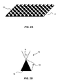
- FIGS. 2A and 2B show an embodiment of the separator device according to the invention or a detailed view of it.
- FIG. 1 the structure of a device is shown with which a high-resolution Can generate image with a CCD device.
- An item 1 that is pictured is, for example, a film whose chemically stored information to be recorded electronically. But it can also be any act object to be photographed in the landscape.
- the subject 1 is the imaging optics 2 in front of or behind an entrance opening 3 Device mapped to an image plane 4 within the device.
- This The first image 5 of the object 1 should be from an image storage device 14 Storing light information comprising a plurality of image storage elements 15, can be saved.
- the image storage device 14 is shown in FIG. 1 the CCD device. Your individual image storage elements 15 have a given one geometric extension, which is denoted by d in Fig. 1, and are individually readable electronically.
- the image storage elements 15 have the size d, which is significantly greater than that of e.g. If there are grains in the photographic layer of a film, you have to spatial resolution of the information stored by the CCD device increase by at least a first of the image 5 of the object 1 and a second half image is captured. Both half figures (or more generally the several partial images) together result in the image of the object 1 on the image storage device 14. Because of this decomposition of the image It is the object 1 in two half or more partial images possible, each of these half or partial images with the highest resolution Capture image storage device 14. This results in two half images a later processing of the data from the image storage device 14 Doubling the resolution, with four quarters, the result is a fourfold increase the dissolution etc.
- a separator device 6 is provided, which in of the illustrated embodiment is arranged in the image plane 4.
- the separator device 6 turns off light the image plane 4 in at least a first direction 7 and a second direction 8 distracted.
- a first part of the light from that Item 1 hits a first deflecting mirror 9a, which in particular arrives Concave mirror is.
- the light arrives via a first light propagation path 11 a second deflecting mirror 10a and finally from this onto the image storage device 14 with the individual image storage elements 15.
- This first part of the light from the object 1, which passes through the first light propagation path 11 reaches the image storage device 14, produces a first half image there of the image 5 in the image plane 4.
- 8 deflected light strikes in the second direction, i.e. a second part of the Light from the object 1, on a second deflecting mirror 9b, which in particular is a concave mirror. Arrived via a second light propagation path 12 the light to a second deflecting mirror 10b and from this finally to the Image storage device 14 with the individual image storage elements 15. This second part of the light from the object 1, which is via the second light propagation path 12 arrives at the image storage device 14, generates one there second half image of the image 5 in the image plane 4.
- each of the at least two light propagation paths 11, 12 selectively opened and closed one after the other.
- This half or Partial images are stored individually in a memory (not shown) and then processed further.
- the number of picture elements in the following Editing can be selected twice as high as the number of image storage elements 15 of the image storage device 14 with which the images are captured and saved.
- a closure device 13 which has so many closure elements how has light propagation paths.
- the closure device comprises 13 a first shutter 13a in the light propagation path 11 and a second shutter 13b in the light propagation path 12.
- a logical connection (not shown) of the two closures 13a and 13b, one of the two light propagation paths 11 and 12 is selectively opened, and the other light propagation path is interrupted.
- FIG. 2A shows an embodiment of the separator device 6 in the image plane 4 shown.
- This is a multiple deflection device in the form a blaze plate 17, which has a plurality of reflector elements 18.
- the blaze plate 17 essentially covers the entire image plane 4 of the device from. Light that falls on it, depending on the point of impact, is on one of the reflector elements 18 deflected in one of four directions, analogous to directions 7 and 8 in FIG. 1.
- the blaze plate has small mirror pyramids 18 on each "pixel" of the image 5 in the image plane 4 in four Divide up "partial pixels".
- these reflector elements 18 have four side surfaces 19 on.
- the four side surfaces 19 are preferably similar Surface segments because the light is on all intended light propagation paths (Two in Fig. 1, namely 11 and 12) should be evenly distributed.
- close opposite side surfaces 19 an angle ⁇ . From the side surfaces 19, the light from the image plane 4 is reflected as explained above, so that it covers four light propagation paths to the image storage device and there four different ones Generated images.
- the individual elements of the separator device 6 do not have to reflect. So in an alternative embodiment (not shown) is the separator device 6 Instead of a blaze plate, a transparent plate instead of the reflector elements 18 comprises several prism elements with four side surfaces, which in turn enclose an angle ⁇ . In this case, the light is not from that Elements of the separator device 6 are reflected, but instead it is broken so that it is over four light propagation paths (behind the separator device) to the image storage device 14.
- the number of reflector elements is 18 or the number of prism elements in particular equal to the number of image storage elements 15 a clear assignment of the individual elements to capture the image information.
- the invention is not limited to the embodiments described above.
- the separator device 6 is thus shown in the image plane 4, i.e. in the level of an intermediate image. In practice this is an advantage. But it is also conceivable that the imaging optics 2 at the input 3 of the invention Device the object 1 directly onto the image storage device 14 is mapped and an intermediate image 5 is not first generated by it, i.e. image plane 4 and image storage device 14 coincide.
Landscapes
- Engineering & Computer Science (AREA)
- Multimedia (AREA)
- Signal Processing (AREA)
- Studio Devices (AREA)
Abstract
Description
- 1
- Gegenstand
- 2
- Abbildungsoptik
- 3
- Eingang der Vorrichtung
- 4
- Bildebene in der Vorrichtung
- 5
- Bild von Gegenstand in Bildebene
- 6
- Separatorvorrichtung
- 7
- erste Richtung
- 8
- zweite Richtung
- 9
- erster Spiegel, 9a erster Spiegel links, 9b erster Spiegel rechts
- 10
- zweiter Spiegel, 10a zweiter Spiegel links, 10b zweiter Spiegel rechts
- 11
- erster Lichtausbreitungspfad
- 12
- zweiter Lichtausbreitungspfad
- 13
- Verschlussvorrichtung, 13a Verschlussvorrichtung in erstem Lichtausbreitungspfad, 13b Verschlussvorrichtung in zweitem Lichtausbreitungspfad
- 14
- Bildspeichervorrichtung, CCD- Vorrichtung
- 15
- Bildspeicherelement
- 16
- Abbildung auf Bildspeichervorrichtung
- 17
- Blaze- Platte
- 18
- Reflektorelement der Blaze- Platte
- 19
- Seitenfläche von Reflektorelement
- d
- geometrischen Ausdehnung
- ϕ
- Winkel zwischen Seitenflächen eines Reflektorelements
Claims (9)
- Vorrichtung zum elektronischen Erfassen eines hochaufgelösten Bildes (5) eines Gegenstandes (1) mit einer Bildspeichervorrichtung (14) zum Speichern von Lichtinformation, die mehrere Bildspeicherelemente (15) mit einer gegebenen geometrischen Ausdehnung (d) aufweist, und einer Abbildungseinrichtung (2), die den Gegenstand (1) auf eine Bildebene (4) in der Vorrichtung abbildet, gekennzeichnet durch eine Separatorvorrichtung (6, 17), durch die ein erster Teil des Lichtes von dem Gegenstand (1) über einen ersten Lichtausbreitungspfad (11) und ein zweiter Teil des Lichtes von dem Gegenstand (1) über einen zweiten Lichtausbreitungspfad (12) zu der Bildspeichervorrichtung (14) abgelenkt wird, so dass eine Abbildung (16) von dem Gegenstand (1) auf der Bildspeichervorrichtung (14) erzeugt wird, und eine Verschlussvorrichtung (13a, 13b), durch die nacheinander jeder der zwei Lichtausbreitungspfade (11, 12) selektiv geöffnet und geschlossen wird, so dass von der Bildspeichervorrichtung (14) nacheinander der erste Teil des Lichts von dem Gegenstand (1) über den ersten Lichtausbreitungspfad (11) und der zweite Teil des Lichts von dem Gegenstand (1) über den zweiten Lichtausbreitungspfad (12) erfasst wird.
- Vorrichtung nach Anspruch 1, dadurch gekennzeichnet, dass die Separatorvorrichtung (6) eine Blaze- Platte (17) ist, die mehrere Reflektorelemente (18) mit jeweils wenigstens zwei Seitenflächen (19) umfasst, die einen Winkel (ϕ) einschließen und von denen das Licht reflektiert wird, so dass es sich über die wenigstens zwei unterschiedlichen Lichtausbreitungspfade (11, 12) zu der Bildspeichervorrichtung (14) ausbreitet.
- Vorrichtung nach Anspruch 2, dadurch gekennzeichnet, dass die Anzahl der Reflektorelemente (18) mindestens gleich der Anzahl der Bildspeicherelemente (15) ist.
- Vorrichtung nach Anspruch 1, dadurch gekennzeichnet, dass die Separatorvorrichtung (6) eine transparente Platte ist, die mehrere Prismenelemente mit jeweils wenigstens zwei Seitenflächen umfasst, die einen Winkel (ϕ) einschließen und von denen das Licht gebrochen wird, so dass es sich über die wenigstens zwei unterschiedlichen Lichtausbreitungspfade (11, 12) zu der Bildspeichervorrichtung (14) ausbreitet.
- Vorrichtung nach Anspruch 4, dadurch gekennzeichnet, dass die Anzahl der Prismenelemente mindestens gleich der Anzahl der Bildspeicherelemente (15) ist.
- Vorrichtung nach einem der Ansprüche 2 bis 5, dadurch gekennzeichnet, dass die Reflektor- oder Prismen- Elemente (18) eine vierseitige Oberfläche haben, so dass das Licht von dem Gegenstand (1) in vier Richtungen abgelenkt wird und sich über vier Lichtausbreitungspfade (11, 12) zu der Bildspeichervorrichtung (14) ausbreitet, und die Verschlussvorrichtung (13a, 13b) zwischen der Separatorvorrichtung (6) und der Bildspeichervorrichtung (14) selektiv einen der vier Lichtausbreitungspfade (11) offen lässt und die restlichen drei Lichtausbreitungspfade (12) unterbricht.
- Vorrichtung nach einem der vorangehenden Ansprüche, dadurch gekennzeichnet, dass die Verschlussvorrichtung (13a, 13b) ein mechanischer Verschluss ist.
- Vorrichtung nach einem der Ansprüche 1 bis 6, dadurch gekennzeichnet, dass die Verschlussvorrichtung (13a, 13b) eine elektronisch ansteuerbare LCD- Vorrichtung ist.
- Verfahren zum elektronischen Erfassen eines Bildes (5) eines Gegenstandes (1) mit den Schritten:Speichern von Lichtinformation durch eine Bildspeichervorrichtung (14), die mehrere Bildspeicherelemente (15) mit einer gegebenen geometrischen Ausdehnung (d) aufweist, undAbbilden des Gegenstands (1) durch eine Abbildungseinrichtung (2) auf eine Bildebene (4) in der Vorrichtung, gekennzeichnet durch die Schritte: Ablenken eines ersten Teils des Lichtes von dem Gegenstand (1) über einen ersten Lichtausbreitungspfad (11) und eines zweiten Teils des Lichtes von dem Gegenstand (1) über einen zweiten Lichtausbreitungspfad (12) zu der Bildspeichervorrichtung (14) durch eine Separatorvorrichtung (6, 17), so dass eine Abbildung (16) von dem Gegenstand (1) auf der Bildspeichervorrichtung (14) erzeugt wird, und selektives Öffnen und Schließen jedes der wenigstens zwei Lichtausbreitungspfade (11, 12) nacheinander durch eine Verschlussvorrichtung (13a, 13b), so dass von der Bildspeichervorrichtung (14) nacheinander der erste Teil des Lichts von dem Gegenstand (1) über den ersten Lichtausbreitungspfad (11) und der zweite Teil des Lichts von dem Gegenstand (1) über den zweiten Lichtausbreitungspfad (12) erfasst wird.
Priority Applications (1)
| Application Number | Priority Date | Filing Date | Title |
|---|---|---|---|
| EP01130030A EP1324585A1 (de) | 2001-12-18 | 2001-12-18 | Vorrichtung und Verfahren zum elektronischen Erfassen eines hochaufgelösten Bildes eines Gegenstandes |
Applications Claiming Priority (1)
| Application Number | Priority Date | Filing Date | Title |
|---|---|---|---|
| EP01130030A EP1324585A1 (de) | 2001-12-18 | 2001-12-18 | Vorrichtung und Verfahren zum elektronischen Erfassen eines hochaufgelösten Bildes eines Gegenstandes |
Publications (1)
| Publication Number | Publication Date |
|---|---|
| EP1324585A1 true EP1324585A1 (de) | 2003-07-02 |
Family
ID=8179582
Family Applications (1)
| Application Number | Title | Priority Date | Filing Date |
|---|---|---|---|
| EP01130030A Withdrawn EP1324585A1 (de) | 2001-12-18 | 2001-12-18 | Vorrichtung und Verfahren zum elektronischen Erfassen eines hochaufgelösten Bildes eines Gegenstandes |
Country Status (1)
| Country | Link |
|---|---|
| EP (1) | EP1324585A1 (de) |
Citations (6)
| Publication number | Priority date | Publication date | Assignee | Title |
|---|---|---|---|---|
| DE3616400A1 (de) * | 1985-05-23 | 1986-11-27 | Steinheil-Lear Siegler AG, 8045 Ismaning | Opto-elektronischer bildumsetzer |
| JPH0193258A (ja) * | 1987-10-05 | 1989-04-12 | Casio Comput Co Ltd | 画像読取装置 |
| CH672385A5 (en) * | 1987-01-30 | 1989-11-15 | Sinar Ag Schaffhausen | Forming digital electronic image fur recording - increasing pixel resolution by stepwise displacement of scene projected across matrix array |
| JPH06276448A (ja) * | 1993-03-17 | 1994-09-30 | Fujitsu Ltd | 撮像装置 |
| JPH10257395A (ja) * | 1997-03-13 | 1998-09-25 | Hitachi Ltd | 画像撮影装置 |
| EP1089548A2 (de) * | 1999-09-29 | 2001-04-04 | Xerox Corporation | Optisches System |
-
2001
- 2001-12-18 EP EP01130030A patent/EP1324585A1/de not_active Withdrawn
Patent Citations (6)
| Publication number | Priority date | Publication date | Assignee | Title |
|---|---|---|---|---|
| DE3616400A1 (de) * | 1985-05-23 | 1986-11-27 | Steinheil-Lear Siegler AG, 8045 Ismaning | Opto-elektronischer bildumsetzer |
| CH672385A5 (en) * | 1987-01-30 | 1989-11-15 | Sinar Ag Schaffhausen | Forming digital electronic image fur recording - increasing pixel resolution by stepwise displacement of scene projected across matrix array |
| JPH0193258A (ja) * | 1987-10-05 | 1989-04-12 | Casio Comput Co Ltd | 画像読取装置 |
| JPH06276448A (ja) * | 1993-03-17 | 1994-09-30 | Fujitsu Ltd | 撮像装置 |
| JPH10257395A (ja) * | 1997-03-13 | 1998-09-25 | Hitachi Ltd | 画像撮影装置 |
| EP1089548A2 (de) * | 1999-09-29 | 2001-04-04 | Xerox Corporation | Optisches System |
Non-Patent Citations (3)
| Title |
|---|
| PATENT ABSTRACTS OF JAPAN vol. 013, no. 330 (E - 793) 25 July 1989 (1989-07-25) * |
| PATENT ABSTRACTS OF JAPAN vol. 018, no. 687 (E - 1651) 26 December 1994 (1994-12-26) * |
| PATENT ABSTRACTS OF JAPAN vol. 1998, no. 14 31 December 1998 (1998-12-31) * |
Similar Documents
| Publication | Publication Date | Title |
|---|---|---|
| DE102012005152B4 (de) | Bildaufnahmevorrichtung und bildaufnahmeoptik | |
| DE2738804C2 (de) | Einrichtung zum Erkennen der Relativbewegung zwischen einem Objekt und dieser Vorrichtung | |
| EP2046027A1 (de) | Anordnung, bei der von einer Lichtquelle aus Licht auf einer Fläche gerichtet wird | |
| DE2942794A1 (de) | Vorrichtung zur elektrischen ermittlung der scharfeinstellung eines objektivs | |
| DE69633589T2 (de) | Verfahren und Gerät zur Verarbeitung von visuellen Informationen | |
| DE102017106831A1 (de) | Kamera und Verfahren zur Erfassung von relativ zu der Kamera in einer Förderrichtung bewegten Objekten | |
| EP1145069A2 (de) | Anordnung, bei der von einer lichtquelle aus licht auf eine fläche gerichtet wird | |
| EP1049064B1 (de) | Verkehrsüberwachungseinrichtung mit Polarisationsfiltern | |
| EP3147700B1 (de) | Verfahren und vorrichtung zur vergrösserung des sichtfelds einer kamera sowie damit ausgestattete kamera | |
| EP0708325A1 (de) | Verfahren und Vorrichtung zur Inspektion von Gegenständen, insbesondere von Flaschen | |
| DE2846696C2 (de) | Automatische Scharfeinstelleinrichtung für ein optisches Abbildungssystem | |
| DE1462446A1 (de) | Verfahren und Vorrichtung zur Bilduebertragung | |
| DE1772745A1 (de) | Fotografische Vielfachkamera | |
| DE10207665A1 (de) | Überwachungskamerasystem und Objektivsystem | |
| DE10304105B4 (de) | Verfahren zur Bestimmung der Fokusabweichung einer optischen Anordnung | |
| WO2002069622A1 (de) | Videokamera und adapter für eine videokamera | |
| WO2008000443A1 (de) | Abbilden optischer bilder auf einen bildsensor mittels einer faseroptischen platte bzw. eines faserkeils | |
| DE1447286A1 (de) | Digitale Strahlablenkeinrichtung | |
| DE2534082A1 (de) | Automatische fokussier-steuervorrichtung | |
| EP4217785B1 (de) | Abbildungssystem, insbesondere für eine kamera | |
| WO2003100518A2 (de) | Verfahren und anordnung zur fotografischen aufnahme eines fahrzeuges | |
| CH678979A5 (de) | ||
| DE2307755A1 (de) | Geraet zum aufsuchen und fernuebertragen mikroverfilmter dokumente | |
| DE102004018633B4 (de) | Bilderzeuger-System und -Verfahren mit Filterung | |
| DE69202566T2 (de) | Schwingpupille-autofokusverfahren und geraet. |
Legal Events
| Date | Code | Title | Description |
|---|---|---|---|
| PUAI | Public reference made under article 153(3) epc to a published international application that has entered the european phase |
Free format text: ORIGINAL CODE: 0009012 |
|
| AK | Designated contracting states |
Designated state(s): AT BE CH CY DE DK ES FI FR GB GR IE IT LI LU MC NL PT SE TR |
|
| AX | Request for extension of the european patent |
Extension state: AL LT LV MK RO SI |
|
| 17P | Request for examination filed |
Effective date: 20040102 |
|
| AKX | Designation fees paid |
Designated state(s): AT BE CH CY DE DK ES FI FR GB GR IE IT LI LU MC NL PT SE TR |
|
| RAP1 | Party data changed (applicant data changed or rights of an application transferred) |
Owner name: AGFAPHOTO GMBH |
|
| 19U | Interruption of proceedings before grant |
Effective date: 20060101 |
|
| 19W | Proceedings resumed before grant after interruption of proceedings |
Effective date: 20100401 |
|
| STAA | Information on the status of an ep patent application or granted ep patent |
Free format text: STATUS: THE APPLICATION IS DEEMED TO BE WITHDRAWN |
|
| 18D | Application deemed to be withdrawn |
Effective date: 20101001 |