EP1322838B1 - Aube de turbomachine et turbomachine - Google Patents
Aube de turbomachine et turbomachine Download PDFInfo
- Publication number
- EP1322838B1 EP1322838B1 EP01971957A EP01971957A EP1322838B1 EP 1322838 B1 EP1322838 B1 EP 1322838B1 EP 01971957 A EP01971957 A EP 01971957A EP 01971957 A EP01971957 A EP 01971957A EP 1322838 B1 EP1322838 B1 EP 1322838B1
- Authority
- EP
- European Patent Office
- Prior art keywords
- blade
- moving blade
- cellular material
- region
- turbomachine
- Prior art date
- Legal status (The legal status is an assumption and is not a legal conclusion. Google has not performed a legal analysis and makes no representation as to the accuracy of the status listed.)
- Expired - Lifetime
Links
Images


Classifications
-
- F—MECHANICAL ENGINEERING; LIGHTING; HEATING; WEAPONS; BLASTING
- F01—MACHINES OR ENGINES IN GENERAL; ENGINE PLANTS IN GENERAL; STEAM ENGINES
- F01D—NON-POSITIVE DISPLACEMENT MACHINES OR ENGINES, e.g. STEAM TURBINES
- F01D5/00—Blades; Blade-carrying members; Heating, heat-insulating, cooling or antivibration means on the blades or the members
- F01D5/12—Blades
- F01D5/14—Form or construction
- F01D5/147—Construction, i.e. structural features, e.g. of weight-saving hollow blades
-
- F—MECHANICAL ENGINEERING; LIGHTING; HEATING; WEAPONS; BLASTING
- F01—MACHINES OR ENGINES IN GENERAL; ENGINE PLANTS IN GENERAL; STEAM ENGINES
- F01D—NON-POSITIVE DISPLACEMENT MACHINES OR ENGINES, e.g. STEAM TURBINES
- F01D5/00—Blades; Blade-carrying members; Heating, heat-insulating, cooling or antivibration means on the blades or the members
- F01D5/12—Blades
- F01D5/28—Selecting particular materials; Particular measures relating thereto; Measures against erosion or corrosion
-
- B—PERFORMING OPERATIONS; TRANSPORTING
- B22—CASTING; POWDER METALLURGY
- B22F—WORKING METALLIC POWDER; MANUFACTURE OF ARTICLES FROM METALLIC POWDER; MAKING METALLIC POWDER; APPARATUS OR DEVICES SPECIALLY ADAPTED FOR METALLIC POWDER
- B22F2998/00—Supplementary information concerning processes or compositions relating to powder metallurgy
-
- F—MECHANICAL ENGINEERING; LIGHTING; HEATING; WEAPONS; BLASTING
- F05—INDEXING SCHEMES RELATING TO ENGINES OR PUMPS IN VARIOUS SUBCLASSES OF CLASSES F01-F04
- F05C—INDEXING SCHEME RELATING TO MATERIALS, MATERIAL PROPERTIES OR MATERIAL CHARACTERISTICS FOR MACHINES, ENGINES OR PUMPS OTHER THAN NON-POSITIVE-DISPLACEMENT MACHINES OR ENGINES
- F05C2201/00—Metals
- F05C2201/04—Heavy metals
- F05C2201/0433—Iron group; Ferrous alloys, e.g. steel
- F05C2201/0463—Cobalt
-
- F—MECHANICAL ENGINEERING; LIGHTING; HEATING; WEAPONS; BLASTING
- F05—INDEXING SCHEMES RELATING TO ENGINES OR PUMPS IN VARIOUS SUBCLASSES OF CLASSES F01-F04
- F05C—INDEXING SCHEME RELATING TO MATERIALS, MATERIAL PROPERTIES OR MATERIAL CHARACTERISTICS FOR MACHINES, ENGINES OR PUMPS OTHER THAN NON-POSITIVE-DISPLACEMENT MACHINES OR ENGINES
- F05C2201/00—Metals
- F05C2201/04—Heavy metals
- F05C2201/0433—Iron group; Ferrous alloys, e.g. steel
- F05C2201/0466—Nickel
-
- F—MECHANICAL ENGINEERING; LIGHTING; HEATING; WEAPONS; BLASTING
- F05—INDEXING SCHEMES RELATING TO ENGINES OR PUMPS IN VARIOUS SUBCLASSES OF CLASSES F01-F04
- F05D—INDEXING SCHEME FOR ASPECTS RELATING TO NON-POSITIVE-DISPLACEMENT MACHINES OR ENGINES, GAS-TURBINES OR JET-PROPULSION PLANTS
- F05D2260/00—Function
- F05D2260/20—Heat transfer, e.g. cooling
- F05D2260/203—Heat transfer, e.g. cooling by transpiration cooling
-
- F—MECHANICAL ENGINEERING; LIGHTING; HEATING; WEAPONS; BLASTING
- F05—INDEXING SCHEMES RELATING TO ENGINES OR PUMPS IN VARIOUS SUBCLASSES OF CLASSES F01-F04
- F05D—INDEXING SCHEME FOR ASPECTS RELATING TO NON-POSITIVE-DISPLACEMENT MACHINES OR ENGINES, GAS-TURBINES OR JET-PROPULSION PLANTS
- F05D2300/00—Materials; Properties thereof
- F05D2300/60—Properties or characteristics given to material by treatment or manufacturing
- F05D2300/612—Foam
Definitions
- the invention relates to a blade for a turbomachine.
- the invention further relates to a turbomachine with a blade.
- Blades for turbomachinery such as blades for high, medium or low pressure turbine part of a steam turbine or gas turbine blades for compressor or turbine, are usually made of homogeneous metallic alloys. In addition to milling processes, casting and forging techniques are used. The metallic raw material is melted and then rolled as bar stock or forged as a blade blank.
- Such a turbomachine comprises a single impeller or a number of impellers arranged one behind the other in the axial direction, the rotor blades of which are surrounded during operation by a gaseous or vaporous flow medium.
- the flow medium exerts a force on the blades, which causes a torque of the rotor or paddle wheel and thus the working power.
- the blades are usually arranged on a rotatable shaft of the turbomachine, whose vanes are arranged on corresponding guide wheels on the stationary, the shaft surrounding the formation of a flow channel housing, the housing of the turbomachine, are arranged.
- the blades of steam turbine low pressure parts are mainly loaded by centrifugal force due to the rotation of the shaft.
- the load is thus directly proportional to the density of the blade material used. Since the densities of the materials used are very similar to those of iron, the load on long ND blades is so great that a certain blade length can not be exceeded. This is particularly important for the higher stages of ND blading whose radial dimensions are limited by the limits of centrifugal load. Due to the limited blade length only a certain outlet cross section for the flow medium can be achieved, so that the flow medium, e.g. the exhaust steam of a low-pressure turbine part, leaves the turbomachine at high speed and consequently with high losses.
- the flow medium e.g. the exhaust steam of a low-pressure turbine part
- Titanium alloys have a lower density compared to alloys based on iron, cobalt or nickel, and rotor blades made of this material are therefore subject to less stress than blades made of the hitherto customary metallic materials with otherwise identical dimensions.
- the disadvantage of this problem solution is that titanium alloys are very expensive and the problem of centrifugal load is still, albeit to a lesser extent.
- the object of the invention is to specify a blade design for a rotor blade for a turbomachine, which does not exceed the permissible stresses at the given loads in the turbomachine and nevertheless allows a high degree of efficiency.
- Another object of the invention is to provide a turbomachine for high loads with high efficiency.
- the object directed to a blade is achieved by a blade for a turbomachine, wherein the blade forms an outer surface with a closed structure with respect to cells and a blade profile consists entirely of a cellular material.
- the invention takes a completely new approach.
- homogeneous metallic materials have been used for the moving blades
- the concept of the invention is based on the structural design of the moving blade and the materials forming it.
- the use of cellular materials for the blade results in a significant reduction in the mean density of the blade.
- the cellular structure ensures a much lower density than previously common homogeneous materials.
- blades according to the invention therefore cause much lower stresses due to the centrifugal force.
- Cellular materials also have a greater internal damping than homogeneous materials, so that they advantageously dampen possible vibrations particularly efficient.
- cellular materials show good stiffness properties, so that they have approximately the permissible load of comparable homogeneous materials due to the high specific strength. This is particularly advantageous when used in a turbomachine, where significant thermo-mechanical loads are recorded.
- the blade preferably has an airfoil portion with the cellular material.
- the blade blade area of a blade is exposed to particularly high blade stresses when using the blade in a turbomachine due to the centrifugal force, since the blade blade area relative to other areas of the blade has a greater radial distance from the axis of rotation.
- An airfoil region having the cellular material results in a correspondingly lower centrifugal load due to the significantly lower density.
- the moving blade preferably has a fastening region, in particular a blade root, wherein the cellular material is provided in the fastening region.
- the attachment of a blade is usually carried out on a rotatable shaft, wherein a mounting region of the blade is connected to a corresponding receiving region of the shaft.
- Various blade attachment concepts are known, such as fir tree slot connections or hammer head connections, to which the new blade concept is applicable.
- By providing the cellular material in the mounting area of the blade the blade stresses can be reduced accordingly also in the attachment area.
- the cellular material may be provided both in the airfoil region and in the attachment region.
- the blade can also consist as a whole of a cellular material, which is achieved due to the reduction in density over a comparable solid material, a lightweight construction of the blade as a whole.
- a cellular structure of the blade is far superior to the use of massive light metals, such as titanium alloys.
- the blade has an inner region and a jacket region surrounding the inner region, wherein the cellular material is provided in the jacket region and in the inner region.
- the cellular material forms an outer surface with closed structure to the cells.
- the outer surface is a partial surface of the blade airfoil region of the rotor blade, wherein the airfoil region is subjected to a flow medium during operation.
- a surface eg a surface in the airfoil region, with correspondingly low roughness is provided.
- the cellular structure of the material provides an outer surface which also has a strong cushioning effect against secondary losses due to cross-flow, provided that the outer surface of the cellular structure is exposed to a flow medium.
- the surface has barriers for a possible transverse flow, which may be formed along adjacent cells of the cellular structure.
- the cellular material is a metal foam.
- metal foams are considered lightweight materials with high potential and a wide range of applications.
- Metal foams can be obtained in various manufacturing processes, for example by means of melting and powder metallurgy deposition and sputtering techniques.
- a replacement material is produced by mixing a metal powder with a blowing agent, for example metal hydride, which is compacted after subsequent axial hot pressing or extrusion to form a prefabricated semi-finished product that can be conformed to shape by appropriate forming to a respective end product and by appropriate heating is foamed to just above the melting temperature of the metal.
- a blowing agent for example metal hydride
- the blowing agent contained in the semifinished product decomposes on heating and splits off hydrogen gas.
- the gaseous hydrogen leads as a propellant gas in the molten metal to the corresponding pore formation.
- the porosity of the metal foam formed by the pores can be adjusted in a targeted manner over the duration of the foaming process.
- the density of the metal foam is between about 5% to 50%, more preferably between about 8% to 20%, of the density of the bulk material.
- the metal foam consists of a high-temperature-resistant material, in particular a nickel-based or cobalt-based alloy.
- a high-temperature resistant material is particularly advantageous for use in a gas turbine, with turbine inlet temperatures of up to 1200 ° C.
- the application in a steam turbine with high steam conditions of more than 600 ° C steam temperature is made possible by this choice of material for the metal foam.
- the blade is configured as a gas turbine blade, a steam turbine blade, particularly a low pressure steam turbine blade, or a compressor blade.
- a low-pressure steam turbine appears to be particularly advantageous because the use of the cellular material, such as a metal foam, larger blade lengths at lower centrifugal load compared to the conventional blades can be realized. This has a directly favorable effect on the efficiency of the turbomachine, for example a low-pressure steam turbine.
- the task directed towards a turbomachine is achieved according to the invention by a turbomachine with a moving blade according to the above statements.
- the turbomachine is designed as a gas turbine, a steam turbine or a compressor.
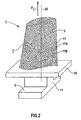
- FIG 1 shows a perspective view of a blade 1, which extends along a longitudinal axis 25.
- the blade has along the longitudinal axis successively a mounting region 9, an adjoining paddle platform 23 and an airfoil region 7.
- a blade root 11 is formed, which serves for fastening the blade 1 to the shaft of a turbomachine, not shown in FIG 1 (see FIG 8).
- the blade root 11 is designed as a hammer head.
- Other configurations, for example as a Christmas tree or Schwalbenschwanzfuß are possible.
- massive metal materials are used in all areas 9, 23, 7 of the blade 1.
- the blade 1 can be made by a casting process, by a forging process, by a milling process or combinations thereof.
- a blade 1 according to the invention is shown in FIG.
- the moving blade 1 is partially made of a cellular material 5 in comparison to the conventional moving blade 1 shown in FIG. 1.
- the cellular material 5 is provided in the blade blade region 7 of the moving blade 1, the entire blade blade region 7 being the cellular material 5 has.
- the cellular material 5 has a plurality of cells 17, 17a, 17b.
- the cell structure of the cellular material 5 may be such that a closed porous structure is achieved with each of the cells 17, 17a, 17b closed.
- the cells 17, 17A, 17B may also form an at least partially non-closed porous structure.
- a region 7 with a significantly reduced material density is provided in the airfoil region 7 compared to conventional blades 1 with a solid material insert (see FIG. This is achieved due to the cellular structure of the material 5. Due to the reduced density in the airfoil region 7, a considerable reduction in the load due to the centrifugal force F z directed radially outward along the longitudinal axis 25 is achieved in the operating case, for example when using the blade 1 in a turbomachine.
- the region of the blade 1, which experiences a larger centrifugal force F z due to the greater radial distance from the axis of rotation, namely the blade blade region 7, is specifically provided with the cellular material.
- the cellular material 5 may be provided in different regions 9, 23, 7 of the blade 1.
- FIG. 3 shows a perspective view of a blade 1 with a modified embodiment with respect to the blade 1 shown in FIG. 2 with regard to the presence of the cellular material 5.
- the cellular material 5 is present according to detail X1 in the attachment area 9 as well as in the area of the blade platform 23 according to detail X2.
- the details X1 and X2 represent exemplary subregions of the attachment region 9 or the blade platform 23.
- the entire attachment region 9 and / or the region of the blade platform 23 can be made of the cellular material 5.
- the cellular material 5 comprises a plurality of cells 17.
- the rotor blade 1 has an inlet edge 31 and an outlet edge 33. Furthermore, the moving blade 1 has a pressure side 35 and a suction side 37 opposite the pressure side 35. A typical blade profile is given by this.
- the rotor blade 1 has an inner region 13 and a jacket region 15 surrounding the inner region 13.
- the jacket region 15 forms an outer surface 39 of the rotor blade 1, wherein the outer surface 39 is acted upon in the case of operation with a flow medium, for example a hot gas or steam.
- the jacket region 15 consists of a conventional, unspecified, for example, metallic solid material 27.
- the inner region 13 consists, at least partially, of a cellular material 5, the cellular material 5 being formed of a metal foam 21 with a multiplicity of adjacent cells 17 is.
- cooling channels 29, 29 A, 29 B are provided, so that the blade 1 is designed in the case of operation for an interior cooling.
- the cooling channels 29, 29 A, 29 B are acted upon by a coolant, for example cooling air or cooling steam.
- the cooling channel 29 serves for example for the supply of the coolant, while the cooling channels 29A, 29B serve for the removal of the coolant.
- the cooling channels 29, 29A, 29B are formed in the inner region 13 by corresponding recesses of the cellular material 5.
- the blade of FIG 3 can hereby For example, be prepared in that the thin-walled the blade profile forming shell portion 15 is ejected as a mold with the metal foam 21, wherein corresponding removable or leachable casting cores for forming the cooling channels 29, 29 A, 29 B are positioned prior to the injection of the metal foam 21 in the inner region 13.
- a thin-walled jacket region 15 is produced, which is supported by the cellular material 5 in the inner region 13 as a support structure.
- FIG. 1 An inventive embodiment of a blade profile of a blade 1 is shown in FIG.
- the jacket region 5 consists of a metal foam 21, which encloses an inner region 13.
- the inner region 13 forms a cavity of the rotor blade 1, so that an interior cooling is possible.
- the jacket region 15 has an outer surface 39, which in the case of operation is acted upon by a flow medium.
- the metal foam 21 forms the outer surface 39.
- FIG. 1 Another variant of a blade 1 is shown in a sectional view in FIG.
- the blade profile completely made of a cellular material 5, in which case a metal foam 21 is provided here again.
- the metal foam 21 forms, as discussed in connection with FIG 5, the metal foam 21 an outer surface 39.
- the inner region 13 and the cladding region 15 of the blade 1 thus consist of cellular material. 5
- FIG. 7 shows an enlarged detail of a detail VII of the rotor blade 1 shown in FIG. 6.
- the cellular structure of the material 5, which is provided here by a metal foam 21, is intended to be clarified hereby.
- a plurality of cells 17, 17A, 17B are shown with cells 17A, 17B contiguous and part of the surface 39 of the blade 1 form.
- cells 17 are also provided which do not form an outer surface 39.
- These cells 17 may also be referred to as inner cells 17.
- the cells 17, 17A, 17B have, in the sectional view, by way of example a polygon structure. In a three-dimensional view this corresponds to polyhedra or linear combinations of polyhedra.
- the cellular material 5 forms an outer surface 39 with a closed structure with respect to the cells 17A, 17B.
- an outer surface 39 of the rotor blade 1 is provided, which has a sufficiently low surface roughness, so that accordingly correspondingly low flow losses are ensured when using the rotor blade 1 in a turbomachine (see FIG. Compared to conventional blades 1, a competitive, if not superior, solution is thus also shown with regard to the smoothest possible surface.
- the local surface structure in the region of adjoining near-surface cells 17A, 17B can in particular significantly reduce the secondary losses as a result of transverse flows.
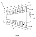
- FIG. 8 a detail of a turbomachine 3 is shown in simplified representation in a longitudinal section using the example of a low-pressure steam turbine 59.
- the low-pressure steam turbine 59 has a rotor 43 which extends along the axis of rotation 41 of the steam turbine 59. Furthermore, the low-pressure steam turbine 59 has an inflow region 49, a blading region 51 and an outflow region 53 along the axis 41 in succession.
- rotatable blades 1 and fixed vanes 45 are arranged in the blading area 51 .
- the rotor blades 1 are fastened to the turbine rotor 43, while the stator blades 45 are arranged on a guide blade carrier 47 surrounding the turbine rotor 43.
- the Beschaufelungs Scheme 51 and the Leitschaufelani 47 is an annular flow channel for a flow medium A, for example, superheated steam formed.
- the inflow region 49 serving to supply the flow medium A is bounded in the radial direction by an inflow housing 55 arranged upstream of the guide vanes carrier 59.
- An outflow housing 57 is disposed downstream of the vane support 47 and defines the outflow region 53 in the radial direction.
- the flow medium A here a superheated steam
- the rotor blades 1 of the low-pressure steam turbine 51 consist, at least in regions, of a cellular material 5, as described in FIGS. 2 to 7.
- the rotor blades 1 have a lower density than conventional rotor blades 1 (see FIG. 1) and are not subjected to such high loads as a result of the centrifugal force.
- the rotor blades 1 form the low-pressure blading of the low-pressure steam turbine 59.
- blades 1 can be used with a larger radial dimension due to the density advantage, so that a larger flow cross-section with lower losses for the blades Steam turbine 59 is realized.
- the guide vanes 45 can also be made in regions of a cellular material 5, so that in the blading region 51 both rotor blades 1 and vanes 45 can be used in lightweight construction. Farther is an application of the new blade concept on other types of turbomachines 3 possible.
- the blading of a gas turbine, a compressor, a high-pressure or medium-pressure turbine part of a steam turbine plant rotor blades 1 and / or vanes 45 with the cellular material 5, in particular a metal foam 21 have.
Landscapes
- Engineering & Computer Science (AREA)
- Mechanical Engineering (AREA)
- General Engineering & Computer Science (AREA)
- Architecture (AREA)
- Chemical & Material Sciences (AREA)
- Materials Engineering (AREA)
- Turbine Rotor Nozzle Sealing (AREA)
- Structures Of Non-Positive Displacement Pumps (AREA)
- Finish Polishing, Edge Sharpening, And Grinding By Specific Grinding Devices (AREA)
Abstract
Claims (9)
- Aube (1) mobile pour une turbomachine (3),
celle-ci étant constituée au moins par partie en un matériau (5) cellulaire, caractérisée en ce que le matériau (5) cellulaire forme une surface (39) extérieure à structure fermée par rapport à des cellules (17, 17A, 17B), et en ce que
le profil de l'aube est constitué entièrement en un matériau cellulaire. - Aube mobile suivant la revendication 1,
comprenant une partie (7) de lame d'aube ayant le matériau (5) cellulaire. - Aube (1) mobile suivant la revendication 1 ou 2,
dans laquelle celle-ci a une zone (9) de fixation, notamment une emplanture (11) d'aube, le matériau (5) cellulaire étant prévu dans la zone (9) de fixation. - Aube (1) mobile suivant l'une des revendications précédentes,
dans laquelle le matériau (5) cellulaire est une mousse (21) métallique. - Aube (1) mobile suivant la revendication 4, dans laquelle la masse volumique de la mousse (21) métallique représente entre environ 5 % et 50 %, notamment entre environ 8 % et 20 % de la masse volumique de la matière (27) pleine.
- Aube (1) mobile suivant la revendication 4 ou 5,
dans laquelle la mousse (21) métallique est en une matière résistante à une température haute, notamment en un alliage à base de nickel ou en un alliage à base de cobalt. - Aube (1) mobile suivant l'une des revendications précédentes,
dans laquelle celle-ci est conformée en aube mobile de turbine à gaz, en aube mobile de turbine à vapeur, notamment en aube mobile de turbine à vapeur basse pression ou en aube mobile de compresseur. - Turbomachine (3) ayant une aube (1) mobile suivant l'une des revendications précédentes.
- Turbomachine (3) suivant la revendication 8,
dans laquelle celle-ci est conformée en turbine à gaz, en turbine (59) à vapeur, notamment en turbine à vapeur basse pression ou en compresseur.
Priority Applications (2)
| Application Number | Priority Date | Filing Date | Title |
|---|---|---|---|
| EP06014569A EP1707745A3 (fr) | 2000-09-05 | 2001-08-23 | Aube de rotor pour une turbomachine et turbomachine |
| EP01971957A EP1322838B1 (fr) | 2000-09-05 | 2001-08-23 | Aube de turbomachine et turbomachine |
Applications Claiming Priority (4)
| Application Number | Priority Date | Filing Date | Title |
|---|---|---|---|
| EP00119203 | 2000-09-05 | ||
| EP00119203A EP1186748A1 (fr) | 2000-09-05 | 2000-09-05 | Aube de rotor pour une turbomachine et turbomachine |
| PCT/EP2001/009759 WO2002020948A1 (fr) | 2000-09-05 | 2001-08-23 | Aube de turbomachine et turbomachine |
| EP01971957A EP1322838B1 (fr) | 2000-09-05 | 2001-08-23 | Aube de turbomachine et turbomachine |
Related Child Applications (1)
| Application Number | Title | Priority Date | Filing Date |
|---|---|---|---|
| EP06014569A Division EP1707745A3 (fr) | 2000-09-05 | 2001-08-23 | Aube de rotor pour une turbomachine et turbomachine |
Publications (2)
| Publication Number | Publication Date |
|---|---|
| EP1322838A1 EP1322838A1 (fr) | 2003-07-02 |
| EP1322838B1 true EP1322838B1 (fr) | 2006-10-11 |
Family
ID=8169757
Family Applications (3)
| Application Number | Title | Priority Date | Filing Date |
|---|---|---|---|
| EP00119203A Withdrawn EP1186748A1 (fr) | 2000-09-05 | 2000-09-05 | Aube de rotor pour une turbomachine et turbomachine |
| EP01971957A Expired - Lifetime EP1322838B1 (fr) | 2000-09-05 | 2001-08-23 | Aube de turbomachine et turbomachine |
| EP06014569A Withdrawn EP1707745A3 (fr) | 2000-09-05 | 2001-08-23 | Aube de rotor pour une turbomachine et turbomachine |
Family Applications Before (1)
| Application Number | Title | Priority Date | Filing Date |
|---|---|---|---|
| EP00119203A Withdrawn EP1186748A1 (fr) | 2000-09-05 | 2000-09-05 | Aube de rotor pour une turbomachine et turbomachine |
Family Applications After (1)
| Application Number | Title | Priority Date | Filing Date |
|---|---|---|---|
| EP06014569A Withdrawn EP1707745A3 (fr) | 2000-09-05 | 2001-08-23 | Aube de rotor pour une turbomachine et turbomachine |
Country Status (6)
| Country | Link |
|---|---|
| US (1) | US6827556B2 (fr) |
| EP (3) | EP1186748A1 (fr) |
| JP (1) | JP4499351B2 (fr) |
| CN (1) | CN1325761C (fr) |
| DE (1) | DE50111221D1 (fr) |
| WO (1) | WO2002020948A1 (fr) |
Families Citing this family (54)
| Publication number | Priority date | Publication date | Assignee | Title |
|---|---|---|---|---|
| DE10331599A1 (de) * | 2003-07-11 | 2005-02-03 | Mtu Aero Engines Gmbh | Bauteil für eine Gasturbine sowie Verfahren zur Herstellung desselben |
| DE10357656A1 (de) * | 2003-12-10 | 2005-07-07 | Mtu Aero Engines Gmbh | Verfahren zur Herstellung von Gasturbinenbauteilen und Bauteil für eine Gasturbine |
| DE10360164A1 (de) * | 2003-12-20 | 2005-07-21 | Mtu Aero Engines Gmbh | Gasturbinenbauteil |
| EP1566519A1 (fr) * | 2004-02-23 | 2005-08-24 | Siemens Aktiengesellschaft | Composant à haute température d'une turbomachine et turbomachine |
| GB2451779A (en) * | 2004-09-22 | 2009-02-11 | Rolls Royce Plc | Manufacturing aerofoil with metal foam core |
| DE102006013557B4 (de) | 2005-03-30 | 2015-09-24 | Alstom Technology Ltd. | Rotor für eine Dampfturbine |
| DE102005044470A1 (de) * | 2005-09-16 | 2007-03-22 | Orbiter Group Beteiligungs Gmbh | Verwendung eines Metallschaumes in Strömungsmaschinen, insbesondere in Turbinen, Lüftern und Pumpen |
| GB0601220D0 (en) * | 2006-01-21 | 2006-03-01 | Rolls Royce Plc | Aerofoils for gas turbine engines |
| DE102006022164B4 (de) * | 2006-05-12 | 2012-07-19 | Mtu Aero Engines Gmbh | Verfahren zum Aussteifen eines Rotorelements |
| DE102007009468A1 (de) * | 2007-02-27 | 2008-08-28 | Mtu Aero Engines Gmbh | Verfahren zur Herstellung eines Strukturelements |
| US7905016B2 (en) * | 2007-04-10 | 2011-03-15 | Siemens Energy, Inc. | System for forming a gas cooled airfoil for use in a turbine engine |
| CN101078354B (zh) * | 2007-06-06 | 2013-03-27 | 北京航空航天大学 | 多孔金属叶片耦合设计方法 |
| GB2450937B (en) * | 2007-07-13 | 2009-06-03 | Rolls Royce Plc | Component with tuned frequency response |
| US7988412B2 (en) * | 2007-08-24 | 2011-08-02 | General Electric Company | Structures for damping of turbine components |
| US7633175B1 (en) * | 2008-05-13 | 2009-12-15 | Florida Turbine Technologies, Inc. | Resonating blade for electric power generation |
| US9938931B2 (en) | 2008-12-23 | 2018-04-10 | General Electric Company | Combined surface cooler and acoustic absorber for turbomachines |
| US8333552B2 (en) * | 2008-06-20 | 2012-12-18 | General Electric Company | Combined acoustic absorber and heat exchanging outlet guide vanes |
| DE102008058142A1 (de) * | 2008-11-20 | 2010-05-27 | Mtu Aero Engines Gmbh | Verfahren zum Herstellen und/oder Reparieren eines Rotors einer Strömungsmaschine und Rotor hierzu |
| DE102008058141A1 (de) * | 2008-11-20 | 2010-05-27 | Mtu Aero Engines Gmbh | Verfahren zum Herstellen einer Schaufel für einen Rotor einer Strömungsmaschine |
| US8246291B2 (en) * | 2009-05-21 | 2012-08-21 | Rolls-Royce Corporation | Thermal system for a working member of a power plant |
| GB0912796D0 (en) | 2009-07-23 | 2009-08-26 | Cummins Turbo Tech Ltd | Compressor,turbine and turbocharger |
| US9341118B2 (en) | 2009-12-29 | 2016-05-17 | Rolls-Royce Corporation | Various layered gas turbine engine component constructions |
| WO2012053024A1 (fr) * | 2010-10-18 | 2012-04-26 | 株式会社 日立製作所 | Aube transsonique |
| US8753093B2 (en) * | 2010-10-19 | 2014-06-17 | General Electric Company | Bonded turbine bucket tip shroud and related method |
| US9004873B2 (en) * | 2010-12-27 | 2015-04-14 | Rolls-Royce Corporation | Airfoil, turbomachine and gas turbine engine |
| US20120167572A1 (en) * | 2010-12-30 | 2012-07-05 | Edward Claude Rice | Gas turbine engine and diffuser |
| US8807944B2 (en) * | 2011-01-03 | 2014-08-19 | General Electric Company | Turbomachine airfoil component and cooling method therefor |
| DE102011014292A1 (de) * | 2011-03-17 | 2012-09-20 | Rolls-Royce Deutschland Ltd & Co Kg | Zwischenstufendichtungsring sowie Verfahren zu dessen Herstellung |
| EP2805019A4 (fr) | 2011-12-30 | 2016-10-12 | Rolls Royce Nam Tech Inc | Procédé de fabrication de composant de turbomachine, de profil aérodynamique, et de turbine à gaz |
| JP5555727B2 (ja) | 2012-01-23 | 2014-07-23 | 川崎重工業株式会社 | 軸流圧縮機翼の製造方法 |
| EP2946078B1 (fr) * | 2013-03-03 | 2019-02-20 | Rolls-Royce North American Technologies, Inc. | Élément de moteur à turbine à gaz doté d'un noyau en mousse et d'une couche externe composite, comprenant fente de refroidissement |
| GB201414495D0 (en) * | 2014-08-15 | 2014-10-01 | Rolls Royce Plc | Blade |
| US9789534B2 (en) | 2015-01-20 | 2017-10-17 | United Technologies Corporation | Investment technique for solid mold casting of reticulated metal foams |
| US9737930B2 (en) | 2015-01-20 | 2017-08-22 | United Technologies Corporation | Dual investment shelled solid mold casting of reticulated metal foams |
| US9789536B2 (en) | 2015-01-20 | 2017-10-17 | United Technologies Corporation | Dual investment technique for solid mold casting of reticulated metal foams |
| US9884363B2 (en) | 2015-06-30 | 2018-02-06 | United Technologies Corporation | Variable diameter investment casting mold for casting of reticulated metal foams |
| US9731342B2 (en) | 2015-07-07 | 2017-08-15 | United Technologies Corporation | Chill plate for equiax casting solidification control for solid mold casting of reticulated metal foams |
| EP3147069A1 (fr) * | 2015-09-24 | 2017-03-29 | Siemens Aktiengesellschaft | Procédé de fabrication d'une aube hybride d'une turbomachine thermique par soudage de rechargement |
| US10605117B2 (en) | 2015-10-08 | 2020-03-31 | General Electric Company | Fan platform for a gas turbine engine |
| EP3222814A1 (fr) * | 2016-03-24 | 2017-09-27 | Siemens Aktiengesellschaft | Aube, procédé de fabrication associé et turbomachine associée |
| EP3249159A1 (fr) * | 2016-05-23 | 2017-11-29 | Siemens Aktiengesellschaft | Aube de turbine et turbomachine associée |
| GB201707836D0 (en) * | 2017-05-16 | 2017-06-28 | Oscar Propulsion Ltd | Outlet guide vanes |
| US10808545B2 (en) * | 2017-07-14 | 2020-10-20 | United Technologies Corporation | Gas turbine engine fan blade, design, and fabrication |
| DE102017214060A1 (de) * | 2017-08-11 | 2019-02-14 | Siemens Aktiengesellschaft | Funktionale Struktur und Komponente für eine Strömungsmaschine |
| EP3480431A1 (fr) * | 2017-11-02 | 2019-05-08 | MTU Aero Engines GmbH | Composant pour une turbine à gaz doté d'une structure ayant un gradient dans le module d'élasticité et procédé de fabrication additive |
| US11078795B2 (en) | 2017-11-16 | 2021-08-03 | General Electric Company | OGV electroformed heat exchangers |
| DE102018207444A1 (de) * | 2018-05-15 | 2019-11-21 | Bayerische Motoren Werke Aktiengesellschaft | Verfahren zur Herstellung eines Strukturbauteils |
| GB201918777D0 (en) | 2019-12-19 | 2020-02-05 | Rolls Royce Plc | Shaft bearing arrangement |
| GB201918781D0 (en) | 2019-12-19 | 2020-02-05 | Rolls Royce Plc | Improved shaft bearing positioning in a gas turbine engine |
| GB201918779D0 (en) | 2019-12-19 | 2020-02-05 | Rolls Royce Plc | Shaft bearings |
| GB201918780D0 (en) | 2019-12-19 | 2020-02-05 | Rolls Royce Plc | Shaft bearings for gas turbine engine |
| GB201918783D0 (en) * | 2019-12-19 | 2020-02-05 | Rolls Royce Plc | Shaft with three bearings |
| GB201918782D0 (en) | 2019-12-19 | 2020-02-05 | Rolls Royce Plc | Shaft bearing arrangement |
| US11834956B2 (en) * | 2021-12-20 | 2023-12-05 | Rolls-Royce Plc | Gas turbine engine components with metallic and ceramic foam for improved cooling |
Family Cites Families (30)
| Publication number | Priority date | Publication date | Assignee | Title |
|---|---|---|---|---|
| GB885322A (en) * | 1957-01-31 | 1961-12-28 | Federal Mogul Bower Bearings | A process of fabricating transpiration cooled turbine blades and the blades producedthereby |
| GB1130285A (en) * | 1967-05-05 | 1968-10-16 | Rolls Royce | Method of making an aerofoil shaped blade for a fluid flow machine |
| US3567333A (en) * | 1969-01-31 | 1971-03-02 | Curtiss Wright Corp | Gas turbine blade |
| US3810286A (en) * | 1969-09-10 | 1974-05-14 | Universal Cyclops Specialty St | Methods for manufacturing hollow members |
| US3644059A (en) * | 1970-06-05 | 1972-02-22 | John K Bryan | Cooled airfoil |
| US3656863A (en) * | 1970-07-27 | 1972-04-18 | Curtiss Wright Corp | Transpiration cooled turbine rotor blade |
| US3695778A (en) * | 1970-09-18 | 1972-10-03 | Trw Inc | Turbine blade |
| US3778188A (en) * | 1972-09-11 | 1973-12-11 | Gen Motors Corp | Cooled turbine rotor and its manufacture |
| JPS5216841B2 (fr) * | 1974-06-18 | 1977-05-12 | ||
| JPS5121010A (ja) * | 1974-08-14 | 1976-02-19 | Tokyo Shibaura Electric Co | Gasutaabinyoku |
| DE2503285C2 (de) * | 1975-01-28 | 1984-08-30 | MTU Motoren- und Turbinen-Union München GmbH, 8000 München | Verfahren zur Herstellung eines einstückigen thermisch hochbeanspruchten gekühlten Bauteils, insbesondere einer Schaufel für Turbinentriebwerke |
| JPS5519959A (en) * | 1978-07-29 | 1980-02-13 | Kawasaki Heavy Ind Ltd | Cooling wing |
| GB2042648B (en) * | 1979-02-24 | 1983-05-05 | Rolls Royce | Gas turbine engine hollow blades |
| JPS59153902A (ja) * | 1983-02-23 | 1984-09-01 | Hitachi Ltd | 冷却翼 |
| JPH01127631A (ja) * | 1987-11-10 | 1989-05-19 | Agency Of Ind Science & Technol | 発泡金属の製造方法 |
| DE3902032A1 (de) * | 1989-01-25 | 1990-07-26 | Mtu Muenchen Gmbh | Gesintertes leichtbaumaterial mit herstellungsverfahren |
| JPH03230859A (ja) * | 1990-02-07 | 1991-10-14 | Mitsubishi Heavy Ind Ltd | 軽量アルミニウム鋳物の製造方法 |
| JP3237115B2 (ja) * | 1990-05-29 | 2001-12-10 | スズキ株式会社 | Ti―Al系金属間化合物の発泡体製造方法と製品 |
| FR2688264A1 (fr) * | 1992-03-04 | 1993-09-10 | Snecma | Redresseur de turbomachine a aubes ayant une face alveolee chargee en materiau composite. |
| US5690473A (en) * | 1992-08-25 | 1997-11-25 | General Electric Company | Turbine blade having transpiration strip cooling and method of manufacture |
| DE4338457C2 (de) * | 1993-11-11 | 1998-09-03 | Mtu Muenchen Gmbh | Bauteil aus Metall oder Keramik mit dichter Außenschale und porösem Kern und Herstellungsverfahren |
| JPH07293204A (ja) * | 1994-04-27 | 1995-11-07 | Mitsubishi Heavy Ind Ltd | ガスタービン冷却翼 |
| US5634771A (en) * | 1995-09-25 | 1997-06-03 | General Electric Company | Partially-metallic blade for a gas turbine |
| JP3352584B2 (ja) * | 1996-03-11 | 2002-12-03 | 神鋼鋼線工業株式会社 | 金属発泡体の製造方法 |
| JPH1054204A (ja) * | 1996-05-20 | 1998-02-24 | General Electric Co <Ge> | ガスタービン用の多構成部翼 |
| ES2193439T3 (es) * | 1997-06-10 | 2003-11-01 | Goldschmidt Ag Th | Cuerpo metalico espumable. |
| JP3462750B2 (ja) * | 1998-05-14 | 2003-11-05 | 住友電気工業株式会社 | ディーゼルエンジン用パティキュレートトラップ |
| DE19928871A1 (de) * | 1999-06-24 | 2000-12-28 | Abb Research Ltd | Turbinenschaufel |
| DE10024302A1 (de) * | 2000-05-17 | 2001-11-22 | Alstom Power Nv | Verfahren zur Herstellung eines thermisch belasteten Gussteils |
| US6544003B1 (en) * | 2000-11-08 | 2003-04-08 | General Electric Co. | Gas turbine blisk with ceramic foam blades and its preparation |
-
2000
- 2000-09-05 EP EP00119203A patent/EP1186748A1/fr not_active Withdrawn
-
2001
- 2001-08-23 EP EP01971957A patent/EP1322838B1/fr not_active Expired - Lifetime
- 2001-08-23 WO PCT/EP2001/009759 patent/WO2002020948A1/fr active IP Right Grant
- 2001-08-23 EP EP06014569A patent/EP1707745A3/fr not_active Withdrawn
- 2001-08-23 JP JP2002525339A patent/JP4499351B2/ja not_active Expired - Fee Related
- 2001-08-23 DE DE50111221T patent/DE50111221D1/de not_active Expired - Lifetime
- 2001-08-23 CN CNB018149537A patent/CN1325761C/zh not_active Expired - Fee Related
-
2003
- 2003-03-05 US US10/379,987 patent/US6827556B2/en not_active Expired - Fee Related
Also Published As
| Publication number | Publication date |
|---|---|
| EP1322838A1 (fr) | 2003-07-02 |
| DE50111221D1 (de) | 2006-11-23 |
| EP1707745A3 (fr) | 2006-10-18 |
| JP2004508478A (ja) | 2004-03-18 |
| EP1186748A1 (fr) | 2002-03-13 |
| WO2002020948A1 (fr) | 2002-03-14 |
| EP1707745A2 (fr) | 2006-10-04 |
| JP4499351B2 (ja) | 2010-07-07 |
| CN1325761C (zh) | 2007-07-11 |
| US6827556B2 (en) | 2004-12-07 |
| US20030185685A1 (en) | 2003-10-02 |
| CN1449470A (zh) | 2003-10-15 |
Similar Documents
| Publication | Publication Date | Title |
|---|---|---|
| EP1322838B1 (fr) | Aube de turbomachine et turbomachine | |
| EP2663414B1 (fr) | Procédé de fabrication générative d'un élément à système d'amortissement intégré pour turbomachine et élément à système d'amortissement intégré pour turbomachine fabriqué de façon générative | |
| DE10337866B4 (de) | Verfahren zur Herstellung von Bauteilen für Gasturbinen | |
| EP3191244B1 (fr) | Procédé de production d'une aube mobile et aube obtenue | |
| EP1173657B1 (fr) | Aube de turbine et son procede de production | |
| EP1979577B1 (fr) | Segment d'aube de guidage d'une turbine a gaz et procede pour sa fabrication | |
| EP1702138B1 (fr) | Composant de turbine a gaz | |
| EP2483019A2 (fr) | Aube de turbine et procédé de fabrication de ladite aube | |
| EP2719484A1 (fr) | Composant et procédé destiné à la fabrication du composant | |
| WO2011054342A1 (fr) | Disque aubagé monobloc, turbine à gaz et procédé de fabrication d'un tel disque aubagé monobloc | |
| DE102014012480A1 (de) | Beschaufelung einer Strömungsmaschine, Herstellverfahren und Laufrad einer Strömungsmaschine | |
| CH694257A5 (de) | Dampfturbine. | |
| EP1462617B1 (fr) | Aubage pour une turbomachine axiale | |
| WO2010108983A1 (fr) | Plaque d'étanchéité et système d'aubes mobiles | |
| DE102021115229A1 (de) | Lagerkammergehäuse für eine strömungsmaschine | |
| EP3147069A1 (fr) | Procédé de fabrication d'une aube hybride d'une turbomachine thermique par soudage de rechargement | |
| EP2404036A1 (fr) | Procédé de fabrication d'un rotor aubagé monobloc | |
| WO2008067796A2 (fr) | Couronne d'aubes fixes et procédé de fabrication | |
| EP0492207B1 (fr) | Aube pour machines à écoulement | |
| EP1355041A2 (fr) | Aube de turbine | |
| EP2159380A1 (fr) | Dispositif de turbine à gaz avec carter poreux et son procédé de fabrication | |
| EP1462614B1 (fr) | Turbine thermique à écoulement axial | |
| EP1895094B1 (fr) | Rotor avec cordon de soudure refroidi par tourbillon | |
| DE102010050712A1 (de) | Bauelement einer Strömungsmaschine und Verfahren zum generativen Herstellen eines derartigen Bauelementes | |
| EP3231995A1 (fr) | Aube de turbine comprenant des pales de turbine et une enveloppe de pale |
Legal Events
| Date | Code | Title | Description |
|---|---|---|---|
| PUAI | Public reference made under article 153(3) epc to a published international application that has entered the european phase |
Free format text: ORIGINAL CODE: 0009012 |
|
| 17P | Request for examination filed |
Effective date: 20030210 |
|
| AK | Designated contracting states |
Designated state(s): AT BE CH CY DE DK ES FI FR GB GR IE IT LI LU MC NL PT SE TR |
|
| AX | Request for extension of the european patent |
Extension state: AL LT LV MK RO SI |
|
| RBV | Designated contracting states (corrected) |
Designated state(s): CH DE FR GB IT LI |
|
| GRAP | Despatch of communication of intention to grant a patent |
Free format text: ORIGINAL CODE: EPIDOSNIGR1 |
|
| GRAS | Grant fee paid |
Free format text: ORIGINAL CODE: EPIDOSNIGR3 |
|
| GRAA | (expected) grant |
Free format text: ORIGINAL CODE: 0009210 |
|
| AK | Designated contracting states |
Kind code of ref document: B1 Designated state(s): CH DE FR GB IT LI |
|
| REG | Reference to a national code |
Ref country code: GB Ref legal event code: FG4D Free format text: NOT ENGLISH |
|
| REG | Reference to a national code |
Ref country code: CH Ref legal event code: EP |
|
| REF | Corresponds to: |
Ref document number: 50111221 Country of ref document: DE Date of ref document: 20061123 Kind code of ref document: P |
|
| GBT | Gb: translation of ep patent filed (gb section 77(6)(a)/1977) |
Effective date: 20070125 |
|
| ET | Fr: translation filed | ||
| PLBE | No opposition filed within time limit |
Free format text: ORIGINAL CODE: 0009261 |
|
| STAA | Information on the status of an ep patent application or granted ep patent |
Free format text: STATUS: NO OPPOSITION FILED WITHIN TIME LIMIT |
|
| 26N | No opposition filed |
Effective date: 20070712 |
|
| PGFP | Annual fee paid to national office [announced via postgrant information from national office to epo] |
Ref country code: GB Payment date: 20130814 Year of fee payment: 13 Ref country code: FR Payment date: 20130814 Year of fee payment: 13 |
|
| PGFP | Annual fee paid to national office [announced via postgrant information from national office to epo] |
Ref country code: IT Payment date: 20130827 Year of fee payment: 13 |
|
| PGFP | Annual fee paid to national office [announced via postgrant information from national office to epo] |
Ref country code: CH Payment date: 20131107 Year of fee payment: 13 Ref country code: DE Payment date: 20131021 Year of fee payment: 13 |
|
| REG | Reference to a national code |
Ref country code: DE Ref legal event code: R119 Ref document number: 50111221 Country of ref document: DE |
|
| REG | Reference to a national code |
Ref country code: CH Ref legal event code: PL |
|
| GBPC | Gb: european patent ceased through non-payment of renewal fee |
Effective date: 20140823 |
|
| PG25 | Lapsed in a contracting state [announced via postgrant information from national office to epo] |
Ref country code: CH Free format text: LAPSE BECAUSE OF NON-PAYMENT OF DUE FEES Effective date: 20140831 Ref country code: LI Free format text: LAPSE BECAUSE OF NON-PAYMENT OF DUE FEES Effective date: 20140831 Ref country code: IT Free format text: LAPSE BECAUSE OF NON-PAYMENT OF DUE FEES Effective date: 20140823 |
|
| REG | Reference to a national code |
Ref country code: DE Ref legal event code: R119 Ref document number: 50111221 Country of ref document: DE Effective date: 20150303 |
|
| REG | Reference to a national code |
Ref country code: FR Ref legal event code: ST Effective date: 20150430 |
|
| PG25 | Lapsed in a contracting state [announced via postgrant information from national office to epo] |
Ref country code: GB Free format text: LAPSE BECAUSE OF NON-PAYMENT OF DUE FEES Effective date: 20140823 Ref country code: DE Free format text: LAPSE BECAUSE OF NON-PAYMENT OF DUE FEES Effective date: 20150303 |
|
| PG25 | Lapsed in a contracting state [announced via postgrant information from national office to epo] |
Ref country code: FR Free format text: LAPSE BECAUSE OF NON-PAYMENT OF DUE FEES Effective date: 20140901 |