EP1320326B1 - Einrichtung zur kühlung einer fläche, die um eine drehachse rotiert und der drehachse zugekehrt ist - Google Patents
Einrichtung zur kühlung einer fläche, die um eine drehachse rotiert und der drehachse zugekehrt ist Download PDFInfo
- Publication number
- EP1320326B1 EP1320326B1 EP01978170A EP01978170A EP1320326B1 EP 1320326 B1 EP1320326 B1 EP 1320326B1 EP 01978170 A EP01978170 A EP 01978170A EP 01978170 A EP01978170 A EP 01978170A EP 1320326 B1 EP1320326 B1 EP 1320326B1
- Authority
- EP
- European Patent Office
- Prior art keywords
- coolant
- cooled
- axis
- container
- cooling
- Prior art date
- Legal status (The legal status is an assumption and is not a legal conclusion. Google has not performed a legal analysis and makes no representation as to the accuracy of the status listed.)
- Expired - Lifetime
Links
Images

Classifications
-
- A—HUMAN NECESSITIES
- A61—MEDICAL OR VETERINARY SCIENCE; HYGIENE
- A61B—DIAGNOSIS; SURGERY; IDENTIFICATION
- A61B6/00—Apparatus or devices for radiation diagnosis; Apparatus or devices for radiation diagnosis combined with radiation therapy equipment
- A61B6/02—Arrangements for diagnosis sequentially in different planes; Stereoscopic radiation diagnosis
- A61B6/03—Computed tomography [CT]
- A61B6/032—Transmission computed tomography [CT]
- A61B6/035—Mechanical aspects of CT
-
- A—HUMAN NECESSITIES
- A61—MEDICAL OR VETERINARY SCIENCE; HYGIENE
- A61B—DIAGNOSIS; SURGERY; IDENTIFICATION
- A61B6/00—Apparatus or devices for radiation diagnosis; Apparatus or devices for radiation diagnosis combined with radiation therapy equipment
- A61B6/44—Constructional features of apparatus for radiation diagnosis
- A61B6/4488—Means for cooling
Definitions
- the invention relates to a device for cooling a Surface that rotates about an axis of rotation and facing the axis of rotation is.
- a system is also called a "gantry”.
- the limiting size for the maximum achievable rotation frequency is the total mass to be rotated which in addition to the X-ray detector u.a. the mass of the X-ray source, the mass of the device for electrical power supply the X-ray source and the mass of one with the X-ray source co-rotating means for Cooling of a hot surface of the device for electrical Energy supply includes.
- by reducing the size of components of the radius of rotation are reduced, so that Total results in a reduction in centrifugal force.
- a reduction of each contributing to the total mass individual Mass by itself already causes a reduction of the total mass, as well as a reduction in the mass of the facility for cooling a hot surface of the device for the electrical power supply of the X-ray source.
- the specified in claim 1 invention advantageously a device for cooling a rotating about an axis and the axis facing surface ready with the Coated surface and has a low-mass structure.
- the device according to the invention essentially comprises: A container for a liquid coolant between the Axis and the surface to be cooled with a Mitrotation with Surface is arranged, and at least one of the surface facing Atomizing nozzle of the container from which the coolant during the rotation of the container due to the on the coolant Centrifugal force acting as an atomizing jet in the container exit that hits the surface.
- the inventive device skillfully uses the rotation to use an efficient atomization cooling process out.
- the highly effective method of the known "Spray Coolings” with all its benefits be used with the centrifugal force advantageous as a “compressor” becomes.
- the centrifugal force acts on the coolant in the rotating Container and generates a high enough pressure that is sufficient to put the coolant through the atomizing nozzle to spray the surface to be cooled.
- the device according to the invention is advantageously general applicable everywhere, where one rotating around an axis and the axis facing surface to cool, and allowed because of their mass poverty advantageously a high maximum achievable rotational frequency or an increase in the Rotation or circulation frequency compared to the standard technology due to the reduction of centrifugal force
- An advantageous embodiment of the device according to the invention is designed or could be designed that the atomizing jet is not vertical, but oblique meets the surface to be cooled at an angle. Thereby can be an optimal homogeneity of the area to be cooled sprayed coolant and thus improved cooling obtained / achieved.
- this embodiment is the angle at which the atomizing jet is obliquely up the surface to be cooled hits, depending on the rotation frequency adjustable to this surface.
- An obliquely at an angle to the surface to be cooled Atomizing beam arises when the Atomizing beam with a perpendicular to the surface directed Beam axis emerges from the atomizing nozzle.
- the atomizing jet is on the way from the nozzle to be cooled Area due to the action of Coriolis force in the Curved plane of rotation and obliquely hits at an angle on the surface. The amount of this angle depends on the rotation frequency and the larger the rotation frequency, the greater is.
- the angle at which the Atomizing jet obliquely hits the surface to be cooled, by the angle of the beam axis relative to this surface be set. The latter angle can be dependent on the rotational frequency of the surface are set / be.
- An advantageous development of the device according to the invention has a closed coolant circulation device on, in which the atomized coolant after impact collected on the surface to be cooled and in the container is returned.
- the coolant circuit device has a Cooling surface on, at the coolant, which at the to be cooled Surface evaporated, condensed.
- the device according to the invention is to be cooled Surface becomes a hot surface around a tube for recording of a patient to be examined rotating electronic Device for supplying electrical energy to the X-ray source of a computer tomograph.
- the illustrated in the figure 1 part of the gantry of an exemplary Computer tomograph has an axis 1, the is perpendicular to the plane of Figure 1, and around the the rotating part of the gantry of the tomograph is turning.
- the axis 1 is at the same time a longitudinal axis of the only indicated stationary tube 2 for receiving a patient of the gantry.
- the recorded patient is in the interior 20 of the tube. 2 along the axis also located in the interior 20 1 postponed.
- the part of the gantry rotating about the axis 1 and the tube 2 of the tomograph includes i.a. an X-ray source, the X-ray detector, an electronic device for electrical power supply of the X-ray source and a device for cooling a surface to be cooled Hot-going setup of the rotating part of the gantry.
- the hot device is symbolic in FIG represented by a box marked 3. she is mounted on the rotating part of the gantry and rotated synchronous with this part about the axis 1 and the tube 2, for example, in the direction of arrow 10.
- the hot device 3 is preferably Device constructed with semiconductor devices for the electrical power supply of the X-ray source, wherein the surface to be cooled one of the axis 1 facing hot Expected area of this device is, and / or the X-ray source Even with the surface to be cooled one of the Axis 1 facing hot surface of the anode this Source, preferably a back surface of grounded Anode, is.
- the area of the device to be cooled is 3 symbolically by the axis 1 facing side surface of the Shown box, which is designated 30.
- the to be cooled Surface 30 is, for example, perpendicular to the plane of the drawing of the figure 1.
- the means for cooling the surface 30 to be cooled is denoted by 4 and between the tube 2 and to be cooled Surface 30 of the device 3 is arranged.
- the container 40 between the tube 2 and the surface 30th the device 3 is arranged and the axis 1 in the interior 20 of the tube 2 is the container 40 is inevitable between the axis 1 and the axis 1 facing this and to be cooled surface 30 of the device 3, what matters in the end.
- the co-rotation of the container 40 with the device 3 and the area 30 means that the container 40 is synchronous with the device 3 and the surface 30 in the direction of Arrow 10 rotates about the axis 1, for example by the fact that the container 40 and the device 3 firmly connected are.
- the centrifugal force F generated about the axis 1 during the rotation of the container 40 and acting on the coolant 41 in the container 40 acts radially away from the axis 1, ie in the direction of the arrow 11.
- the amount of centrifugal force F is represented by
- m ⁇ r ⁇ ⁇ 2 , where m is the mass of the coolant 41, r is the radial distance of the coolant 41 from the axis 1 during rotation, and ⁇ is the angular velocity of the rotation.
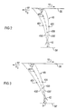
- a moving on the beam axis 430 and exiting the sputtering nozzle 42 coolant particle 431 moves on the way to the surface 30 is not rectilinear, but due to the acting Coriolis force F c , which acts in the direction of the arrow 10 opposite arrow 10 ' , deflected and moves on a in Fig. 2 to the left curved path, which defines the now curved beam axis or beam trajectory 430 of the sputtering beam 43.
- the angle ⁇ depends on the angular velocity ⁇ of the rotation and thus from the rotational frequency. Is this for? Achieving a sufficiently small angle ⁇ ⁇ 90 ° unsuitable so can be helped by the atomizing jet 43 with an angle at an angle to be cooled Surface 30 directed beam axis 430 from the atomizing nozzle 42 exit.
- FIG 3 such a case is shown.
- the figure 3 differs from Figure 2 only in that the Beam axis 430 in the region of the Zerstäubungsdüse 42 opposite the direction of rotation 10 obliquely at an angle ⁇ ⁇ 90 ° to the left inclined to level 30.
- the angle ⁇ can in this case by adjusting the angle ⁇ can be set depending on the rotation frequency, in particular to one always for the cooling of the surface 30th optimal value.
- atomizing 42 instead of only one atomizing 42 and two or a plurality of atomizing nozzles 42 may be present whose atomizing jets 43 the surface 30 in particular obliquely from different Meet directions.
- the area to be cooled 30 can for example also obliquely a radially aligned atomizing nozzle 42 is arranged Moreover, it does not have to be flat, but it can be convex and / or concavely curved.
- the device 4 of Figure 1 for cooling the surface 30 of Device 3 has a closed coolant circulation device 5, in which the atomized coolant 41 after the impact impinged on the surface 30 to be cooled and collected in the container 40 is returned.
- this has Coolant circuit device 5 a cooling surface 50, on the coolant 41, which evaporates on the surface 30 to be cooled is condensed.
- the device works as follows: The constantly on the surface to be cooled 30 sprayed coolant 41st forms on this surface 30 indicated by dashed lines Coolant film 411 from which coolant 41 is constantly evaporated.
- Coolant vapor 412 moves due to centrifugal force F radially away from the axis 1, which is due to the curvature the dashed arrows is indicated, and reaches a completing the rotating parts of the tomograph radially outward, co-rotating and preferably about the axis 1 curved wall 6, for example, by a during the Rotation of self-generated air flow cooled from the outside becomes.
- the axis 1 facing surface of the wall forms the cooling surface 50, to which the refrigerant vapor 412 passes and on the coolant vapor 412 separates as coolant condensate, the one evenly over the entire cooling surface 50th forms distributed coolant film 413, the centrifugal force F presses against the cooling surface 50.
- shutting down the rotation frequency could be in the Coolant film 413 contained coolant 41, for example automatically drain off via sidewalls 7 in the direction of the axis 1, collected in collecting funnels 8 and from the collecting funnels 8 are returned to the container 40.
- the return of the collected coolant 41 may, if necessary, e.g. with steady rotation of the gantry, be supported by pumps 9. However, complicate Such pumps 9 increase the structure of the device 4 and the mass to be set in rotation.
- coolant 41 is preferably an inert coolant used that does not react chemically with the parts with which it comes into contact.
- inert coolant used that does not react chemically with the parts with which it comes into contact.
- Fluorinert be used.
- the device 3 is for electrical Power supply of the X-ray source of the tomograph with standard available components and power electronics modules built, which are relatively heavy and a low Have ratio of chip to housing ground.
- the cooling is done by active air or water cooling, where the water cooling works more effectively, but also one means higher technical complexity and with larger masses connected is. But the air cooling means by the necessary heat storage capacity of the heat sink considerable Volume and thus weight.
- the device according to the invention for cooling a surface, which rotates about an axis of rotation and facing the axis of rotation is not limited to the application in a tomograph.
Landscapes
- Health & Medical Sciences (AREA)
- Life Sciences & Earth Sciences (AREA)
- Engineering & Computer Science (AREA)
- Medical Informatics (AREA)
- Radiology & Medical Imaging (AREA)
- Molecular Biology (AREA)
- Biophysics (AREA)
- Nuclear Medicine, Radiotherapy & Molecular Imaging (AREA)
- Optics & Photonics (AREA)
- Pathology (AREA)
- Physics & Mathematics (AREA)
- Biomedical Technology (AREA)
- Heart & Thoracic Surgery (AREA)
- High Energy & Nuclear Physics (AREA)
- Surgery (AREA)
- Animal Behavior & Ethology (AREA)
- General Health & Medical Sciences (AREA)
- Public Health (AREA)
- Veterinary Medicine (AREA)
- Pulmonology (AREA)
- Theoretical Computer Science (AREA)
- Apparatus For Radiation Diagnosis (AREA)
- X-Ray Techniques (AREA)
Abstract
Description
- Sie kann Wärme hocheffizient von der zu kühlenden Fläche der Einrichtung zur elektrischen Energieversorgung der Röntgenstrahlquelle und/oder der Röntgenstrahlquelle selbst abführen;
- ihre Massearmut vermindert die in Rotation zu setzende Gesamtmasse des Tomographen (rotierender Teil der Gantry) und ermöglicht eine erwünschte höhere maximal erreichbare Rotationsfrequenz, welche die Effizienz des Tomographen durch Erhöhung der pro Zeiteinheit durchführbaren Tomographieuntersuchungen erhöht bzw. die Darstellung schnell bewegter Organe artefaktfrei ermöglicht;
- sie erfordert nur, dass die Einrichtung zur elektrischen Energieversorgung der Röntgenstrahlquelle so anzuordnen ist, dass deren zu kühlende Fläche der Rotationsachse zugekehrt ist;
- sie erlaubt den Aufbau der Einrichtung zur elektrischen Energieversorgung der Röntgenstrahlquelle mit Leistungselektronik-Bauelementen, wodurch sich die in Rotation zu setzende Gesamtmasse des Tomographen noch einmal verringert und die maximal erreichbare Rotationsfrequenz noch einmal gesteigert wird, und wodurch die Baugröße des rotierenden Teils des Tomographen und der Rotationsradius beträchtlich verringert wird.
- Figur 1
- eine schematische Darstellung eines Ausführungsbeispiels einer erfindungsgemäßen Einrichtung zur Kühlung einer auf dem rotierenden Teil der Gantry eines Computer-Tomographen befestigten und mit diesem Teil mitrotierenden heiß werdenden Fläche der Gantry,
- Figur 2
- eine schematische Darstellung, die den aus einer Zerstäubungsdüse des Ausführungsbeispiels der erfindungsgemäßen Einrichtung mit einer zur zu kühlenden Fläche senkrechten Strahlachse austretenden Zerstäubungsstrahls zeigt, der aufgrund der einwirkenden Coriolis-Kraft schräg in einem Winkel auf die Fläche trifft, und
- Figur 3
- eine schematische Darstellung, die den aus der Zerstäubungsdüse des Ausführungsbeispiels der erfindungsgemäßen Einrichtung mit einer schräg in einem Winkel zur zu kühlenden Fläche gerichteten Strahlachse austretenden Zerstäubungsstrahls zeigt, der schräg in einem Winkel auf die Fläche trifft.
Claims (7)
- Einrichtung (4) zur Kühlung einer Fläche (30), die um eine Achse (1) rotiert und der Achse (1) zugekehrt ist,mit einem Behälter (40) für ein flüssiges Kühlmittel (41), der zwischen der Drehachse (1) und der Fläche (30) zu einer Mitrotation mit der Fläche (30) angeordnet ist, undmit mindestens einer der Fläche (30) zugekehrten Zerstäubungsdüse (42) des Behälters (40), aus der das Kühlmittel (41) während der Rotation des Behälters (40) aufgrund der auf das Kühlmittel (41) im Behälter (40) wirkenden Fliehkraft (F) als ein Zerstäubungsstrahl (43) austritt, der auf die Fläche (30) trifft.
- Einrichtung nach Anspruch 1, wobei der Zerstäubungsstrahl (43) schräg in einem Winkel (α) auf die zu kühlende Fläche (30) trifft.
- Einrichtung nach Anspruch 2, wobei der Winkel (α), unter dem der Zerstäubungsstrahl (43) schräg auf die zu kühlende Fläche (30) trifft, abhängig von der Rotationsfrequenz diese Fläche (30) einstellbar ist.
- Einrichtung nach einem der vorhergehenden Ansprüche, mit einer geschlossenen Kühlmittelkreislaufeinrichtung (5), in welcher das zerstäubte Kühlmittel (41) nach dem Auftreffen auf die zu kühlende Fläche (30) gesammelt und in den Behälter (40) rückgeführt wird.
- Einrichtung nach Anspruch 4, wobei die Kühlmittelkreislaufeinrichtung (5) eine Kühlfläche (50) aufweist, an der Kühlmittel (412), das an der zu kühlenden Fläche (30) verdampft ist, kondensiert.
- Einrichtung nach einem der vorhergehenden Ansprüche, wobei die zu kühlende Fläche (30) eine heiß werdende Fläche einer um eine Röhre (2) zur Aufnahme eines zu untersuchenden Patienten rotierenden elektronischen Einrichtung zur elektrischen Energieversorgung der Röntgenstrahlquelle eines Computer-Tomographen ist.
- Einrichtung nach einem der vorhergehenden Ansprüche, wobei die zu kühlende Fläche (30) eine heiß werdende Fläche eines Targets einer um eine Röhre (2) zur Aufnahme eines zu untersuchenden Patienten rotierenden Röntgenstrahlquelle eines Computer-Tomographen ist.
Applications Claiming Priority (3)
| Application Number | Priority Date | Filing Date | Title |
|---|---|---|---|
| DE10048488 | 2000-09-29 | ||
| DE10048488A DE10048488A1 (de) | 2000-09-29 | 2000-09-29 | Einrichtung der Kühlung einer Fläche, die um eine Drehachse rotiert und der Drehachse zugekehrt ist |
| PCT/DE2001/003641 WO2002026132A1 (de) | 2000-09-29 | 2001-09-20 | Einrichtung zur kühlung einer fläche, die um eine drehachse rotiert und der drehachse zugekehrt ist |
Publications (2)
| Publication Number | Publication Date |
|---|---|
| EP1320326A1 EP1320326A1 (de) | 2003-06-25 |
| EP1320326B1 true EP1320326B1 (de) | 2005-08-24 |
Family
ID=7658222
Family Applications (1)
| Application Number | Title | Priority Date | Filing Date |
|---|---|---|---|
| EP01978170A Expired - Lifetime EP1320326B1 (de) | 2000-09-29 | 2001-09-20 | Einrichtung zur kühlung einer fläche, die um eine drehachse rotiert und der drehachse zugekehrt ist |
Country Status (5)
| Country | Link |
|---|---|
| US (1) | US6904128B2 (de) |
| EP (1) | EP1320326B1 (de) |
| JP (1) | JP4605740B2 (de) |
| DE (2) | DE10048488A1 (de) |
| WO (1) | WO2002026132A1 (de) |
Cited By (1)
| Publication number | Priority date | Publication date | Assignee | Title |
|---|---|---|---|---|
| CN103630560A (zh) * | 2013-11-04 | 2014-03-12 | 大连理工大学 | 一种用于低温样品ct扫描的装置及方法 |
Families Citing this family (6)
| Publication number | Priority date | Publication date | Assignee | Title |
|---|---|---|---|---|
| DE102006054055A1 (de) * | 2006-11-16 | 2008-06-05 | Siemens Ag | Gehäusewandung für ein Detektorgehäuse und Detektorgehäuse |
| JP5200039B2 (ja) * | 2009-06-26 | 2013-05-15 | 株式会社日立メディコ | X線装置 |
| DE102010013604B4 (de) | 2010-03-31 | 2014-07-17 | Siemens Aktiengesellschaft | CT-System mit Flüssigkeitskühlung |
| CN104856712A (zh) * | 2015-06-02 | 2015-08-26 | 上海钧安医疗设备技术有限公司 | 一种x射线球管的冷却装置 |
| CN113218132B (zh) * | 2021-04-29 | 2022-04-29 | 扬州辰亚光学科技有限公司 | 一种电子设备光学零部件研发冷却装置 |
| WO2024154219A1 (ja) * | 2023-01-17 | 2024-07-25 | 株式会社アールエフ | X線発生装置 |
Family Cites Families (12)
| Publication number | Priority date | Publication date | Assignee | Title |
|---|---|---|---|---|
| JPS5275996A (en) * | 1975-12-20 | 1977-06-25 | Toshiba Corp | X-ray tube for analysis |
| JPS57162248A (en) * | 1981-03-31 | 1982-10-06 | Hitachi Ltd | Rotary anode x-ray tube |
| JPS6364252A (ja) * | 1986-09-05 | 1988-03-22 | Ulvac Corp | X線発生源の冷却装置 |
| US4997129A (en) * | 1988-10-03 | 1991-03-05 | Waldrum John E | Low cost applicator and method of use |
| JPH0367995A (ja) * | 1989-08-08 | 1991-03-22 | Nippondenso Co Ltd | 熱交換器 |
| US5299249A (en) * | 1992-11-27 | 1994-03-29 | Picker International, Inc. | Heat transfer techniques for moving thermal energy from high power X-ray tubes on rotating CT gantries to a remote location |
| US5440608A (en) * | 1993-07-13 | 1995-08-08 | David V. Habif, Jr. | Method and system for extending the service life of an x-ray tube |
| JPH0927394A (ja) * | 1995-07-10 | 1997-01-28 | Toshiba Corp | X線管装置 |
| JP3587410B2 (ja) * | 1996-04-17 | 2004-11-10 | 株式会社東芝 | X線ct装置 |
| US5978447A (en) * | 1997-11-11 | 1999-11-02 | Picker International, Inc. | X-ray tube straddle bearing assembly |
| DE19820432A1 (de) * | 1998-05-07 | 1999-11-11 | Voith Sulzer Papiertech Patent | Verfahren und Vorrichtung zum Aufbringen eines Auftragsmediums auf einen laufenden Untergrund |
| DE19945415A1 (de) * | 1999-09-22 | 2001-04-12 | Siemens Ag | Kühleinrichtung und Computertomograph mit einer derartigen Kühleinrichtung |
-
2000
- 2000-09-29 DE DE10048488A patent/DE10048488A1/de not_active Withdrawn
-
2001
- 2001-09-20 EP EP01978170A patent/EP1320326B1/de not_active Expired - Lifetime
- 2001-09-20 WO PCT/DE2001/003641 patent/WO2002026132A1/de not_active Ceased
- 2001-09-20 JP JP2002529965A patent/JP4605740B2/ja not_active Expired - Fee Related
- 2001-09-20 DE DE50107220T patent/DE50107220D1/de not_active Expired - Lifetime
- 2001-09-20 US US10/381,883 patent/US6904128B2/en not_active Expired - Fee Related
Cited By (2)
| Publication number | Priority date | Publication date | Assignee | Title |
|---|---|---|---|---|
| CN103630560A (zh) * | 2013-11-04 | 2014-03-12 | 大连理工大学 | 一种用于低温样品ct扫描的装置及方法 |
| CN103630560B (zh) * | 2013-11-04 | 2016-01-13 | 大连理工大学 | 一种用于低温样品ct扫描的装置及方法 |
Also Published As
| Publication number | Publication date |
|---|---|
| JP2004509688A (ja) | 2004-04-02 |
| US20040028185A1 (en) | 2004-02-12 |
| US6904128B2 (en) | 2005-06-07 |
| DE50107220D1 (de) | 2005-09-29 |
| JP4605740B2 (ja) | 2011-01-05 |
| WO2002026132A1 (de) | 2002-04-04 |
| DE10048488A1 (de) | 2002-04-25 |
| EP1320326A1 (de) | 2003-06-25 |
Similar Documents
| Publication | Publication Date | Title |
|---|---|---|
| DE69624126T2 (de) | Rotierendes wärmeübertragungsgerät | |
| EP0973620B2 (de) | Vorrichtung und verfahren zum reinigen oder trocknen von werkstücken | |
| DE3943374C2 (de) | ||
| WO2008068005A1 (de) | Lenkluftring mit einer ringmulde und entsprechender glockenteller | |
| AT404468B (de) | Verfahren zur behandlung von druckvergasungsgasen, insbesondere zur kühlung, entstaubung und wasserdampfsättigung von gasen unter druck, sowie vorrichtung zur durchführung des verfahrens | |
| WO2015124182A1 (de) | Düsenkopf | |
| WO2002026132A1 (de) | Einrichtung zur kühlung einer fläche, die um eine drehachse rotiert und der drehachse zugekehrt ist | |
| DE102010034869A1 (de) | Turbo-Trocknung durch Luftmesser | |
| DE102009034730A1 (de) | Nebelkühlung | |
| DE102007021011A1 (de) | Vorrichtung und Verfahren zur Rohrinnenreinigung | |
| DE102004018133B3 (de) | Anordnung zur Erzeugung eines Trockeneispartikel-Strahls sowie deren Verwendung | |
| DE3248440C2 (de) | ||
| EP0504740B1 (de) | Verteilergebläse | |
| DE69022427T2 (de) | Verfahren und vorrichtungen für scheideverfahren. | |
| DE4335507A1 (de) | Pulversprühorgan | |
| DE1421317A1 (de) | Anordnung zum Auswaschen eines Gases | |
| DE102022207387A1 (de) | Kühlhülsenoptimierung | |
| DE2845505A1 (de) | Verfahren zur wiedergewinnung von energie aus hochofen-abgas und vorrichtung zur durchfuehrung des verfahrens | |
| WO2014139665A1 (de) | Ultraschall-vernebelungsvorrichtung | |
| DE69820569T2 (de) | Kühlgerät | |
| DE102009037410B4 (de) | Erosionsschutz für Dampfturbinenstufen | |
| DE102006052256B4 (de) | Verfahren und Vorrichtung zum Reinigen von Röhrchen | |
| DE3834670A1 (de) | Duese zum austragen von fluessigem duenger | |
| DE202024100306U1 (de) | Schleuderapparat | |
| DE1041878B (de) | Fluessigkeitszerstaeuber |
Legal Events
| Date | Code | Title | Description |
|---|---|---|---|
| PUAI | Public reference made under article 153(3) epc to a published international application that has entered the european phase |
Free format text: ORIGINAL CODE: 0009012 |
|
| 17P | Request for examination filed |
Effective date: 20030305 |
|
| AK | Designated contracting states |
Designated state(s): AT BE CH CY DE DK ES FI FR GB GR IE IT LI LU MC NL PT SE TR |
|
| RBV | Designated contracting states (corrected) |
Designated state(s): CH DE FR GB LI |
|
| GRAP | Despatch of communication of intention to grant a patent |
Free format text: ORIGINAL CODE: EPIDOSNIGR1 |
|
| GRAS | Grant fee paid |
Free format text: ORIGINAL CODE: EPIDOSNIGR3 |
|
| GRAA | (expected) grant |
Free format text: ORIGINAL CODE: 0009210 |
|
| AK | Designated contracting states |
Kind code of ref document: B1 Designated state(s): CH DE FR GB LI |
|
| REG | Reference to a national code |
Ref country code: GB Ref legal event code: FG4D Free format text: NOT ENGLISH |
|
| REG | Reference to a national code |
Ref country code: CH Ref legal event code: EP Ref country code: CH Ref legal event code: NV Representative=s name: SIEMENS SCHWEIZ AG |
|
| REF | Corresponds to: |
Ref document number: 50107220 Country of ref document: DE Date of ref document: 20050929 Kind code of ref document: P |
|
| GBT | Gb: translation of ep patent filed (gb section 77(6)(a)/1977) |
Effective date: 20050915 |
|
| ET | Fr: translation filed | ||
| PLBE | No opposition filed within time limit |
Free format text: ORIGINAL CODE: 0009261 |
|
| STAA | Information on the status of an ep patent application or granted ep patent |
Free format text: STATUS: NO OPPOSITION FILED WITHIN TIME LIMIT |
|
| 26N | No opposition filed |
Effective date: 20060526 |
|
| PGFP | Annual fee paid to national office [announced via postgrant information from national office to epo] |
Ref country code: CH Payment date: 20081211 Year of fee payment: 8 |
|
| REG | Reference to a national code |
Ref country code: CH Ref legal event code: PCAR Free format text: SIEMENS SCHWEIZ AG;INTELLECTUAL PROPERTY FREILAGERSTRASSE 40;8047 ZUERICH (CH) |
|
| REG | Reference to a national code |
Ref country code: CH Ref legal event code: PL |
|
| PG25 | Lapsed in a contracting state [announced via postgrant information from national office to epo] |
Ref country code: LI Free format text: LAPSE BECAUSE OF NON-PAYMENT OF DUE FEES Effective date: 20090930 Ref country code: CH Free format text: LAPSE BECAUSE OF NON-PAYMENT OF DUE FEES Effective date: 20090930 |
|
| PGFP | Annual fee paid to national office [announced via postgrant information from national office to epo] |
Ref country code: GB Payment date: 20120917 Year of fee payment: 12 |
|
| PGFP | Annual fee paid to national office [announced via postgrant information from national office to epo] |
Ref country code: FR Payment date: 20121002 Year of fee payment: 12 |
|
| PGFP | Annual fee paid to national office [announced via postgrant information from national office to epo] |
Ref country code: DE Payment date: 20121119 Year of fee payment: 12 |
|
| GBPC | Gb: european patent ceased through non-payment of renewal fee |
Effective date: 20130920 |
|
| REG | Reference to a national code |
Ref country code: DE Ref legal event code: R119 Ref document number: 50107220 Country of ref document: DE Effective date: 20140401 |
|
| REG | Reference to a national code |
Ref country code: FR Ref legal event code: ST Effective date: 20140530 |
|
| PG25 | Lapsed in a contracting state [announced via postgrant information from national office to epo] |
Ref country code: GB Free format text: LAPSE BECAUSE OF NON-PAYMENT OF DUE FEES Effective date: 20130920 |
|
| PG25 | Lapsed in a contracting state [announced via postgrant information from national office to epo] |
Ref country code: DE Free format text: LAPSE BECAUSE OF NON-PAYMENT OF DUE FEES Effective date: 20140401 Ref country code: FR Free format text: LAPSE BECAUSE OF NON-PAYMENT OF DUE FEES Effective date: 20130930 |