BACKGROUND OF THE INVENTION
(Field of the Invention)
The present invention relates to a gas-sensing device using a solid
electrolyte plate, and in particular, to a gas-sensing device capable of
detecting, for example, the density of a specific gas dissolved in the
exhaust gas in order to control the combustion of an engine and others.
Preferably, such a gas-sensing device is mounted to the exhaust system
of an internal combustion engine.
(Description of the Related Art)
In general, an automobile engine has an exhaust system that
includes a gas sensor used for controlling the combustion. Such a gas-sensing
device is equipped with a solid electrolyte plate, a measurement
electrode disposed on a first surface of the partially stabilized zirconia so
as to face an atmosphere of a gas to be measured, and a reference
electrode disposed on a second surface of the partially stabilized zirconia
so as to face an atmosphere of a reference gas. A gas-permeable
diffusion layer is laminated on the measurement electrode, while a gas-non-permeable
shield layer is laminated on the diffusion layer. Further,
a reference-gas-chamber forming plate is laminated on the second
surface of the solid electrolyte plate so that a reference gas chamber is
formed to face the reference electrode.
However, due to the fact that the solid electrolytic plate is located
between the reference gas chamber and the chamber of a gas to be
measured, the solid electrolyte plate tends to break or crack easily when
manufactured. Particularly, during the cooling step that follows the
calcination carried out after fabricating the gas-sensing device, the solid
electrolyte plate has been apt to break or crack.
SUMMARY OF THE INVENTION
The present invention has been made to overcome the above
problem. An object of the present invention is to provide a gas-sensing
device that has resistance against defects of a solid electrolyte plate, such
as breakage and cracks.
In order to achieve the foregoing object, as one aspect of the
present invention, there is provided a gas-sensing device, which is
subjected to a cooling step from 1470 °C to 457 °C after calcinating the
gas-sensing device during production thereof. The gas-sensing device
comprises a solid electrolyte plate made of partially stabilized zirconia; a
measurement electrode disposed on a first surface of the solid electrolyte
plate so as to face an atmosphere of a gas to be measured; a reference
electrode disposed on a second surface of the solid electrolyte plate so as
to face an atmosphere of a reference gas; a gas-permeable diffusion layer
laminated on the first surface of the solid electrolyte plate so as to cover
the measurement electrode; a gas-non-permeable shield layer laminated
on the diffusion layer; and a reference-gas-chamber forming plate
laminated on the second surface of the solid electrolyte plate so as to form
a reference gas chamber to face the reference electrode. In this sensing
device, at least one of the shield layer, the diffusion layer, and the
reference-gas-chamber forming plate is made from a material that differs
in a contraction percentage from the solid electrolyte plate by an amount
of 0.3 % or less.
According to the foregoing configuration, the gas-sensing device is
produced using green sheets. The green sheets are laminated one on
another, and pressed to adhere mutually to form an un-calcinated
lamination member. This un-calcinated lamination member is then
heated for calcination. The lamination member that has been calcinated
is then cooled down to the room temperature, during which the cooling
step a difference between the contraction percentages of the components
is significant.
In cases where a difference between the contraction percentages
of the solid electrolyte plate and at least one of the shield layer, diffusion
layer, and reference-gas-chamber forming plate is larger than 0.3 %,
such difference is too large to prevent breakage or cracks of the solid
electrolyte plate. That is, since a stress caused in the solid electrolyte
plate becomes larger, there arises a possibility that the plate breaks or
cracks.
In contrast, if such difference is 0 %, that is, the contraction
percentages of all the solid electrolyte plate, shield layer, diffusion layer
and reference-gas-chamber forming plate are equal one to another, there
will be caused no stress on account of differences among those members.
In that case, the solid electrolyte plate will highly resist against its
breaking or cracks, thus providing the plate with the best suitable
condition.
A temperature environment higher than 1470 °C exceeds a heat-resistant
limit of the gas-sensing device, so that there is a possibility that
the solid electrolyte plate, reference-gas-chamber forming plate, and
others will deteriorate. It is therefore undesirable that the gas-sensing
device is exposed to such a higher temperature atmosphere. With
considering such conditions, there is no problem only when the gas-sensing
device is composed of members whose differences of the
contraction percentages is 0.3 % or less and is used at temperatures of
1470 °C or less.
Furthermore, a partially stabilized zirconia will cause its phase
transition at a temperature of 457 °C, and its contraction percentage also
changes at that temperature. Accordingly, in a temperature region
lower than such a temperature that causes the phase transition, a
difference between the contraction percentages of various types of
ceramics and a solid electrolyte plate, both of which composes a gas-sensing
device, remains smaller in most cases.
Hence, if the difference of the contraction percentages is kept at
0.3 % or less over the temperature range of 1470 °C to 457 °C, the present
invention is able to provide sufficient advantages.
Preferably, as a second aspect of the present invention, at least
one of the shield layer, the diffusion layer, and the reference-gas-chamber
forming plate is made from a material that differs in a
contraction percentage from the solid electrolyte plate by an amount of
0.1 % or less.
Such difference of 0.1 % or less is more reliable in reducing a
stress caused in the solid electrolyte plate which is resultant from a
difference of the contraction percentages. It is therefore possible to
prevent or suppress cracks caused in the solid electrolyte plate during
the cooling step.
As a third aspect of the present invention, it is also preferred that
at least one of the shield layer, the diffusion layer, and the reference-gas-chamber
forming plate is made of partially stabilized zirconia. A
material produced by adding to zirconia a material, such as a several mol
percents of MgO, CaO, rare earth oxide, has a cubic-system fluoric
structure, thus providing stabilized zirconia that causes no phase
transition. Partially stabilizing the structure will produce partially
stabilized zirconia.
Like the solid electrolyte plate, when the components (1) to (6)
listed below are made from the partially stabilized zirconia, resistance to
a stress to be caused during the cooling step can be given to the
components.
Furthermore, components made by mutually combining the listed
components (1) to (6) can be made from the partially stabilized zirconia,
so that resistance to a stress to be caused during the cooling step can be
given to the combined components. The components (1) to (6) are listed
as follows:
In the present invention, the partially stabilized zirconia, made
into both the solid electrolyte plate and shield layer, can be produced by
adding yttria (yttrium oxide) to zirconia (zirconium oxide) by a volume of 4
to 7 mol percents.
The partially stabilized zirconia may be applied partially or
entirely to the shield layer. In the same way, the partially stabilized
zirconia may be applied partially or entirely to the reference-gas-chamber
forming plate, diffusion layer, and solid electrolyte plate, respectively.
It is also preferred that the shield layer be made from the partially
stabilized zirconia and coated with alumina-related insulation layer.
Because the partially stabilized zirconia is weak in resisting hot
water, the shield layer is coated with the alumina-related insulation layer,
which has a higher resistance to hot water. This coating structure
prevents the shield layer from cracking due to the hot water.
The present invention can be applied to a variety of types of gas-sensing
devices which is composed by laminating various kinds of
ceramics layers and a solid electrolyte plate one on another. Such
devices include an oxygen-sensing device, NOx-sensing device, HC-sensing
device, and CO-sensing device. The present invention can also
be reduced into practice in manufacturing a multiple type of sensing
sensor capable of measuring density values of plural types of gases.
BRIEF DESCRIPTION OF THE DRAWINGS
In the accompanying drawings:
DETAILED DESCRIPTION OF PREFERRED EMBODIMENT
A preferred embodiment of the present invention will now be
described with reference to accompanying drawings.
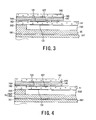
Referring to Figs. 1 to 6, a gas-sensing device 1 according to an
embodiment will now be described. The gas-sensing device 1
manufactured in the embodiment is shown in Figs. 1 to 3.
The gas-sensing device 1 is provided with a solid electrolyte plate
11 made from partially stabilized zirconia. A measurement electrode
121 is disposed on a first surface (i.e., an upper surface in Fig. 1) of the
solid electrolyte plate 11 so as to be exposed to the atmosphere of a gas to
be measured. A reference electrode 131 is disposed on a second surface
(i.e., a lower surface in Fig. 1) of the solid electrolyte plate 11 so as to be
exposed to the atmosphere of a reference gas. On the first surface of the
solid electrolyte plate, a gas-permeable diffusion layer 141 is laminated to
cover the measurement electrode 121. In addition, a gas-non-permeable
shield layer 142 is laminated on the diffusion layer 141.
The shield layer 142 is made from a material that differs in a
contraction percentage from the solid electrolyte plate 11 by an amount of
0.3 % or less. The shield layer 142 is also made from partially stabilized
zirconia that has the same composition as that of the solid electrolyte
plate 11.
On the other hand, on the second surface of the solid electrolyte
plate 11 is disposed a reference-gas-chamber forming plate 15 to form a
reference gas chamber to face the reference electrode 131.
The gas-sensing device 1 is subjected to a cooling step of 1470 °C
to 457 °C carried out after a calcination step of components that have
been fabricated.
The foregoing gas-sensing device 1 will now be detailed. This
gas-sensing device 1 is used as a device to be incorporated into a gas
sensor installed at the exhaust system of an automobile engine. The
gas-sensing sensor is in charge of measuring a density of oxygen in the
exhaust gas. Based on measurements, an air-fuel ratio of the engine is
detected to control the combustion in the engine.
As shown in Figs. 1 to 3, in this embodiment, the gas-sensing
device 1 includes the reference-gas-chamber forming plate 15, solid
electrolyte plate 11, diffusion layer 141, and shield layer 142, which are
overlaid one on another in this order.
The reference-gas-chamber forming plate 15 is shaped to have a
groove 150 that is rectangular in section. The groove 150 provides a
reference gas chamber into which a reference gas is introduced.
The solid electrolyte plate 11 accepts both the measurement
electrode 121 and the reference electrode 131 on its surfaces. Each of
the electrodes 121 and 122 is connected to each of electric leads 122 and
132.
The diffusion layer 141 is overlaid on the solid electrolyte plate 11
so as to cover the measurement electrode 121, and the shield layer is
further overlaid on the diffusion layer 141.
Further, the gas-sensing device 1 is integrally equipped with a
ceramic heater 19 arranged on a side of the reference-gas-chamber
forming plate 15 which is opposite to the solid electrolyte plate 11.
The ceramic heater 19 includes a heater sheet 191, heating
element 181 placed on the a heating element 181, leads 182 to supply
current to the heating element 181, and two heater insulating plates 195
and 197 inserted so as to cover the heating element 181.
One of the heater insulating plates 195 and 197, that is, the plate
195 has a window 196, which is the same in the shape as that of the
heating element 181 and the leads 182. Hence both the heating element
181 and the leads 182 can be embedded into the window 196. The
window 196 is placed to smoothen irregularities arising when both the
heating element 181 and leads 182 are placed between the heater sheet
191 and the heater insulating plate 197.
The leads 182 are electrically connected with terminals 183 via
conductive through holes 190 formed through the heater sheet 191.
Adhesive layers 161, 162 and 165 are placed between the heater
insulating plate 197 and the reference-gas-chamber forming plate 15,
between reference-gas-chamber forming plate 15 and the solid electrolyte
plate 11, and between the diffusion layer 141 and the shield layer 142,
respectively. Moreover, two further adhesive layers 163 and 164 are
inserted into between the solid electrolyte plate 11 and the diffusion layer
141.
In the present embodiment, all the reference-gas-chamber
forming plate 15, diffusion layer 141, heater sheet 191, heater insulating
plates 195 and 197, insulation layer 163, and adhesive layers 161, 162,
164 and 165 are made from alumina.
The composition of each member is as follows.
The reference-gas-chamber forming plate 15 and heater sheet 191
are made from alumina containing zirconia by 2 %. The diffusion layer
141, heater insulating plates 195 and 197, and adhesive layers 161, 162,
164 and 165 are made from alumina of which purity is 99.9 % or more.
The insulation layer 163 is made from alumina of a purity of 99.9 % or
more, with both of a 500 ppm of zirconia and a 300 ppm of magnesia
added thereto. The diffusion layer 141 is made from alumina whose
porosity is 14 %. On the other hand, each of the solid electrolyte plate
11 and the shield layer 142 is made of partially stabilized zirconia
produced by adding a 6 mol percent of yttria to zirconia.
On the second surface of the solid electrolyte plate 11, the
reference electrode 131 is placed so as to face the groove 150 serving as a
reference gas chamber. A window 139 is formed at a particular position
of the foregoing adhesive layer 162 so as to make the window 139 face the
reference electrode 131 through the layer 162. The reference electrode
131 is electrically coupled with a terminal 136 via a lead 132, inner
terminal 133, conductive through hole 134 formed through the solid
electrolyte plate 11, and a through hole 135 formed through the
insulation layer 163. The reference electrode 131, lead 132 and inner
terminal 133 are formed as a mono-layer. As a result, the terminal 136
is placed on the insulation layer 163 formed on the first surface of the
plate 11.
On the other hand, another window 128 is formed at a particular
position of the insulation layer 163 so as to make the window 128 face the
measurement electrode 121. Similarly, another window 129 is formed
at a particular position of the adhesive layer 164 so that the window 129
is able to face the measurement electrode 121. The measurement
electrode 121 on the insulation layer 163 is electrically connected to a
terminal 123 via a lead 122, where all these components 121, 122 and
123 are produced as a one layer.
The gas-sensing element 1 is able to supply its output signal from
the terminals 123 and 136.
As shown in Fig. 3, both of the insulation layer 163 and the
adhesive layer 164 are laminated one on the other so that their windows
128 and 129 communicate to earth other. This lamination produces an
areole 127 in which the measurement electrode 121 is incorporated. A
gas to be measured is introduced into the areole 127 through the
diffusion layer 141.
The manufacturing method of the gas-sensing device 1 according
to the present embodiment will now be explained briefly.
A green sheet for the solid electrolyte plate 11 is first produced
using a doctor blade technique or an extrusion technique. Printing
sections for forming the measurement electrode 121, reference electrode
131, lead 132, and inner terminal 133 are then arranged on the green
sheet. The through hole 134 has already been previously formed
through this green sheet.
An un-calcinated forming body for the reference-gas-chamber
forming plate 15 is formed through injection molding, cutting molding,
press molding, bonding molding, or others.
Additionally, green sheets for the heater sheet 191, shield layer
142, diffusion layer 141 are produced using a doctor blade technique, an
extrusion technique, or others. Of these components, the shield and
diffusion layer 142 and 141 may be produced using paste.
Further, the green sheet for the heater sheet 191 is previously
formed with printing sections for the heating element 181 and others, as
well as the through holes 190.
The foregoing adhesive layers 161, 162, 164 and 165 and the
insulation layer 163 are formed on the green sheets by printing adhesive
and insulating paste thereon, respectively. Of these layers, the layers
164, 162 and 163 with the windows129, 139 and 128 are formed by
screen printing with paste. The heater insulating plates 195 and 197
are also produced by screen printing with paste.
The paste for the insulation layer 163 is first applied to the green
sheet for the solid electrolyte plate 11, and then the printing sections for
the measurement electrode 121, lead 122, and terminals 136 and 123 are
formed on the applied layered paste.
In cases where at least one of the shield layer 142 and the
diffusion layer 141 is formed with the paste, the adhesive layer 165 can
be omitted. Moreover, the diffusion layer 141 can be put, as a single
member, on the adhesive layer 164, if the diffusion layer 141 is produced
using the paste.
The green sheets that have been prepared as above were
laminated in the order shown in Fig. 1, and then pressed, with the result
that the adhesion properties of the adhesive layers 161, 162, 164 and 165
caused the green sheets to adhere one on another. Hence an un-calcinated
lamination member was produced. This member was then
subjected to heating up to 1470 °C for calcination.
The calcinated lamination member was then cooled down to the
room temperature, whereby the gas-sensing device 1 according to the
present embodiment was manufactured.
The performance and advantages of the gas-sensing device 1 will
now be described.
As explained above, after production of the un-calcinated
lamination member, this member undergoes the calcination, before being
cooled down to the room temperature.
Since it is considered that stresses be generated among the shield
layer 142, diffusion layer 141, and solid electrolyte layer 11 during the
cooling step, such stresses can be analyzed from a quantitative
viewpoint.
Provided that the shield layer 142 has factors of a Young's
modulus E1, linear expansion coefficient α1, and thickness t1; the
diffusion layer 141 has factors of a Young's modulus E2, linear expansion
coefficient α2, and thickness t2; and the solid electrolyte plate 11 has
factors of a Young's modulus E3, linear expansion coefficient α3, and
thickness t3, a stress σi to be caused in each layer is given by:
σi = -Ei · Δαi · ΔTi
in which i=1 to 3, Δα is a difference between the linear expansion
coefficients, and ΔT is a change in temperature.
If the cooling step is conducted to impose a negative ΔT on the
calcinated lamination member and its layers and plate have larger linear
expansion coefficients, pulling stresses σ1 to σ3 are to be caused in the
individual layers and plate.
If any external forces act on the member, the forces due to the
pulling stresses will be balanced, whereby an expression of
b(σ1·t1+σ2·t2+σ3·t3)=0
is given, wherein b denotes a width of each layer (plate).
Hence, the expression can be changed to
σ3=-(1/t3)(σ1·t1+σ2·t2).
In manufacturing the gas-sensing device 1 according to the
present embodiment, the linear expansion coefficient of the partially
stabilized zirconia is 10.6 ppm in the temperature range from 1500 °C to
450 °C, while that of the alumina is 8 ppm in the temperature range from
1500 °C to 450 °C.
Hence if the shield layer 142 is made from alumina, the
relationships of σ1<0, σ2<0, and σ3>0 are established. However, the
shield layer 142 of the gas-sensing device 1 according to the present
embodiment has been made from the partially stabilized zirconia, the
relationships of σ1>0, σ2<0, and σ3>0 are established.
Thus, producing the shield layer 142 from the partially stabilized
zirconia makes it possible to reduce σ3 more deeply than the case that
the shield layer 142 is made from alumina.
The solid electrolyte plate 11 is composed of the partially
stabilized zirconia. Since the partially stabilized zirconia changes the
phases from its M-phase (monoclinic phase) to its T-phase (tetragonal
phase) at a temperature of 457 °C, in cases where the partially stabilized
zirconia is cooled down from a higher temperature (about 1500 °C). At
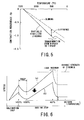
this temperature of 457 °C, as shown in Fig. 5, a slope of the contraction
percentage changes.
In the gas-sensing device 1 according to the present embodiment,
the remaining components other than both the solid electrolyte plate 11
and the shield layer 142 are made from alumina. The alumina changes
its contraction percentage depending on a decrease in temperature, but
the slope of its changes is almost constant, as shown in Fig. 5.
A difference of the contraction percentages between the alumina
and the partially stabilized zirconia becomes a maximum at a
temperature of approximately 457 °C, at which the partially stabilized
zirconia transforms from the M-phase to the T-phase.
A stress applying from the solid electrolyte plate 11 to the shield
layer 142 increases continuously during a period of step for calcinating
the un-calcinated lamination member, as shown in Fig. 6. In Fig. 6, a
curve (a) shows the characteristics of such stress caused in the
conventional type of device in which the shield layer is made from
alumina, whilst a curve (b) shows that of such stress caused in the device
according to the present embodiment.
As shown in Fig. 6, a cooling step follows the calcination step that
finishes at a temperature of some 1470 °C. As soon as the temperature
begins to decrease, the stress also decreases sharply. The reason is that
creep strains are caused in all components including the solid electrolyte
plate 11 and the shield layer 142 due to the fact that the temperature was
high at the end of the calcination step.
After the sharp decrease, as shown in Fig. 6, the stress applying
from the solid electrolyte plate 11 to the shield layer 142 turns over at a
temperature of about 1300 °C, and begins to increase depending on a rise
in the temperature, up to a local maximum at a temperature of about
457 °C. This is attributable to the fact that the difference of the
contraction percentages between the alumina and the partially stabilized
zirconia becomes a maximum at the temperature of about 457 °C.
If the shield layer 142 were made from the alumina, breakage or
cracks would be caused in the solid electrolyte plate 11, because a stress
generated at the point of the local maximum exceeds in strength a
sustainable strength of the partially stabilized zirconia (refer to the curve
(a) shown in Fig. 6).
In contrast, in the present embodiment, as shown by the curve (b)
in Fig. 6, the stress applying from the solid electrolyte plate 11 to the
shield layer 142 can be suppressed to lower levels as a whole.
Significantly, when the stress reaches its local maximum at a
temperature of 457 °C, the strength of the stress is still below the
sustainable strength of the partially stabilized zirconia. Therefore, the
solid electrolyte plate 11 is able to have a higher resistance to breakage
and cracks, thus preventing the product from being defective due to such
an excessive stress. A verification that the defective fraction decrease
thanks to the present invention will be described later.
As stated above, the present embodiment provides the gas-sensing
device that is firmly resistant to defectiveness attributable to
breakage or cracks caused in the solid electrolyte plate.
The reference-gas-chamber forming plate 15 is not limited to a
single body. A modification of such plate 15 can be provided as shown
in Fig. 5, in which the forming plate 15 is composed by a laminated
member consisting of a base plate 151 and a top plate 152 with a hole for
a chamber. When laminated one on the other, the hole of the top plate
152 is able to provide a reference gas chamber 150, thus providing the
same performance and advantages.
(Experiments)
Two types of experiments, which were conducted to confirm the
advantages of the present invention, will now be described.
One type of experiment was carried out on condition that the
gas-sending device 1 had the solid electrolyte plate 11 produced as in the
above embodiment and the shield layer 142 made from the partially
stabilized zirconia. A maximum stress caused in each of the
components of such gas-sensing device 1, which occurs during the
cooling step, was calculated.
For calculation,
specimens 1 to 4 and comparative specimens C1
and C2, which have the same structure as that shown in Fig. 3 or 4 in the
embodiment, were prepared. A table 1 is a list to show types of
compositions of the components of each specimen. The components
include the
solid electrolyte plate 11,
shield layer 142, and others. The
types of compositions include alumina or partially stabilized zirconia
(which is simply noted as "zirconia,").
A finite element method was used to calculate a maximum stress
to be caused in each of the above specimens, and their calculated results
were expressed as a graph in Fig. 7.
From the graph in Fig. 7, it is understood that, when one or more
of the shield layer, diffusion layer, and reference-gas-chamber forming
plate is made from the partially stabilized zirconia which is the same as
the solid electrolyte plate, their maximum stresses to be caused can be
reduced. Thus, the solid electrolyte plate is able to have higher
resistance to its breakage or cracks.
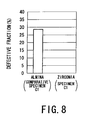
The other experiment was carried out in such a manner that a
large number of gas-sensing devices (specimen 1) each using the partially
stabilized zirconia according to the present invention and a large number
of conventional gas-sensing devices (comparative specimen C1) were
produced, and a defective fraction was examined every type of specimens.
The examination was carried out through an ultra-insulation test to
determine if the devices is defective or not. A defective fraction was then
figured out, every type of specimens. The results are shown in Fig. 8.
As understood from Fig. 8, the gas-sensing devices (specimens 1)
produced in compliance with the above embodiment show a defective
fraction of zero. In contrast, the gas-sensing devices (comparative
specimens C1) show an extremely high defective fraction of slightly lower
than 30 %. The failure in manufacturing gas-sensing devices can
therefore be lessened if the above embodiment is applied to them.
Accordingly, a yield ratio can be raised and a production cost can be
lowered.
The present invention may be embodied in several other forms
without departing from the spirit thereof. The present embodiments as
described is therefore intended to be only illustrative and not restrictive,
since the scope of the invention is defined by the appended claims rather
than by the description preceding them. All changes that fall within the
metes and bounds of the claims, or equivalents of such metes and
bounds, are therefore intended to be embraced by the claims.